


Contents
Scroll to:
https://doi.org/10.23947/2687-1653-2021-21-4-328-336
Scroll to:
Introduction. The paper analyzes the application of composite materials as the main determining method of reducing the mass of the airframe and an unmanned aerial vehicle. Advanced nondestructive testing methods provide assessing the technical condition of these materials, as well as determining stress concentrators on the airframe and an unmanned aerial vehicle with high accuracy in order to make a decision on the further operation of this object under control. The objective of the work was to increase the accuracy and efficiency of the assessment of crack resistance of composite materials through the acoustic emission control.
Materials and Methods. This paper presents the nomenclature of composite materials used in the construction of various aircraft, including unmanned aerial vehicles. The most possible probable defects of these materials due to the influence of operational factors are presented. The applied methods of nondestructive testing of composite material and selection of the most suitable one according to specific advantages were compared. An experiment was carried out to determine the strength limits of carbon fiber using a hardware and software complex by acoustic emission method. The research results are presented in the form of drawings projected by the hardware and software complex.
Results. The application of the acoustic-emission method of composite material control is described.
Discussion and Conclusions. The results obtained experimentally can be used in the process of determining the strength limits of various composite materials by the acoustic emission method of nondestructive testing to assess the technical condition in mechanical engineering, shipbuilding, and aircraft construction. The paper is recommended to researchers involved in the design of aircraft and unmanned aerial vehicles.
Popov A.V., Samuylov A.O., Cherepanov I.S. Application and evaluation of the technical condition of composite materials in aircraft and unmanned aerial vehicles by acoustic emission method of nondestructive testing. Advanced Engineering Research (Rostov-on-Don). 2021;21(4):328-336. https://doi.org/10.23947/2687-1653-2021-21-4-328-336
Introduction. The development of modern aviation technology (AT) is accompanied by the creation of new structural composite materials (CM) with promising mechanical and physical properties. Reducing the takeoff weight is an essential task for the aviation industry. The airframe design of most modern aircraft is made by 53 % of CM, and unmanned aerial vehicles (UAV) — by 90 %. Based on this, there is a need to assess the CM technical condition of the airframe by radiation, thermal, acoustic emission (AE) methods of the nondestructive testing (NDT). A specific feature of the acoustic emission method is the ability to assess the development of various defects.
The objective of the study was to increase the accuracy and efficiency of the assessment of crack resistance of composite materials through the acoustic emission control.
Composite material is man-made material obtained through combining heterogeneous components into one structure, and characterized by better properties compared to the properties of each of the components.
CM has the following distinctive features:
Major advantages and disadvantages of CM are given in Table 1:
Table 1
Major advantages and disadvantages of CM

Figure 1 shows the main materials used in the aircraft industry [1].
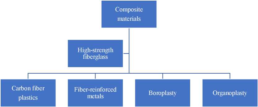
Fig. 1. CM classification
Fiberglass is CM consisting of a polymer matrix and a fiberglass filler, in which gaseous inclusions are present. The application of fiberglass for various purposes is increasing. This is due to the low cost and availability of raw materials, low energy consumption of glass fiber production, versatility, the possibility of regulation within a wide range of physical and mechanical properties, the possibility of creating hybrid materials and structures based on them. Fiberglass products can undergo all types of mechanical processing. The main examples of fiberglass used in the creation of aircraft and UAV include CAST-V sheet, VFT-S, ST-911-1A, SK-9FA, STM-F sealed, VPS-19M sealed [2, 3].
Carbon fiber plastics are CM consisting of a binder and hardeners in the form of carbon fibers, threads, bundles, tapes, or fabrics. Various epoxy or phenol-formaldehyde resins act as binders. The main brands of carbon fiber plastics are CMU-1, CMU-1U, CMU-1B, CMU-1L, CMU-2L, CMU-3L, CMU-3, CMU-4L, CMU-4E, CMU-6-41.
Boron-fiber reinforced plastic is CM that consists of a polymer binder and a hardener — boron fibers. Epoxy and polyamide binders are used as a matrix, and boron filaments or complex boron fiberglass threads are used as hardeners. The use of boron fiberglass threads facilitates the technological process of manufacturing boroplasty. These include CMB-1, CM-1M, CM-1K, MB-2K, MB-3K.
Organoplastics are CM in which fibrous fillers act as a reinforcing filler. Synthetic fibers have good textile properties. A wide range of various structures can be obtained from them: threads, bundles, ribbons, combined fabrics. Synthetic fibers have a light loss of strength under textile processing. They are insensitive to damage. Examples of organoplastics include 7T, 7T0, 5T, 9T, 6 TKS, 6 TKB, 7 TKS, 8 TKS.
Fiber-reinforced metals are CM in which boron fibers, carbon fibers, and filamentous crystals of refractory compounds act as a hardener. Various metals and alloys with characteristic plasticity are used as a matrix.
Examples of such materials include aluminum-boron fiber (VCA-1A), aluminum-carbon fiber (VCU-1), magnesium-boron fiber (VCM-1), magnesium-carbon fiber, nickel-tungsten wire (VCN-1).
The volumes of СM used in the airframe design of an advanced aircraft are different, and they are: wing — 80%, tail — 81%, fuselage — 31%, pylon — 34%, landing gear — 23%. The controls of Il-96-300 aircraft, the rotor blades of Mi-28 helicopter, the airframe of MS-21 aircraft are partially made of CM.
The volume of CM of the UAV airframe reaches 90%. Vivid examples are “Krunk”, “Dozor-600”, “Inokhodets”.
The use of CM in the airframe of aircraft and UAV can significantly lighten their weight. According to formulas (1), (2), it is possible to determine the change in the airframe mass when using CM in it:

where 𝑚плт — mass of the i-th part of the airframe made of traditional materials; 𝑚плк — mass of the i-th part of the airframe made of composite materials; 𝑚 — mass of traditional materials; 𝜑𝑖 — coefficient considering the ratio of the masses of traditional and composite materials whose values lie in the range 0 ≤ 𝜑𝑖 ≤ 1; 𝜀𝑖 — coefficient of the mass denomination of the CM, equal to the ratio of the mass of the elements of the i-th part of the airframe made of CM to the mass of the i-th part of traditional materials 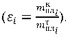
If ∆𝑚𝑛 > 0, then 𝑚плк < 𝑚плт — the airframe made of CM is lighter than an airframe made of traditional materials. Using formulas (1) and (2), it is possible to reduce the airframe weight by 28%, and the UAV — by 60%.
Due to the influence of operational factors (Fig. 2), the following defects may occur in the CM (Table 2 [1]).
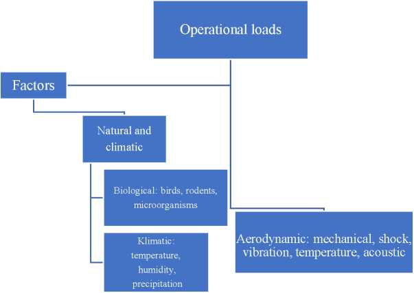
Fig. 2. Classification of operational factors affecting the CM structure [1]
Table 2
Classification and characterization of CM defects

These defects can be diagnosed through the nondestructive testing that provides determining the technical condition of the airframe of an aircraft or UAV without reducing their suitability for use.
These NDT methods include:
The X-ray method is based on the reception and analysis of penetrating the ionizing radiation after interaction with a controlled object. The intensity of the radiation varies depending on the density of the material, its thickness, and the presence of defects1. To register the transmitted radiation, X-ray films of the selected variational sensitivity, fluorescent screens, and television installations are used. Part of the airframe design of an aircraft or UAV is placed in the X-ray installation “SaFair” for monitoring. The result of X-ray radiation is projected on a film in which the defect will be depicted in a color paler than the background of the entire structure. The major disadvantage of the X-ray method is a harmful effect on the object and subject of control [4][5].
The thermal method is based on receiving data on changes in the thermal temperature fields of controlled objects caused by defects. This method is carried out through the use of thermal imagers and aviation heat guns.
Initially, 1/3 of the UAV airframe is heated using an aviation heat gun. At the intermolecular level, energy is transferred from the more heated part of the airframe to the colder one. We observe the process of energy flow using a thermal imager. The coloring of the defect differs from the process described above (Fig. 3) [6–8].
Fig. 3. Image of the UAV airframe defect through applying the thermal method
The disadvantage of this method is the inability to carry out control in unheated rooms.
The ultrasonic method is based on the registration of elastic waves created in the controlled part. Flaw detectors UD2V-P, UDT-40, USD-50 allow detecting cracks of the order of 0.5–1 mm. To carry out control, it is required to establish a contact medium between the controlled part of the airframe of the aircraft or UAV and the receiver-converter of the flaw detector [9–11]. The major disadvantage is a harmful effect on the subject of control.
The AE method is based on the emission of acoustic waves in the process of restructuring of the material. This method is passive since it is based on the registration of low-frequency pulses of defects of parts under loading. The AE method, in comparison to the traditional NDT methods, can detect deep-lying cracks in the structure of the material (Table 3).
Table 3
Comparison of NDT methods

For control, a prototype of the AE diagnostics hardware and software complex was created, which provides real-time recording of developing CM defects in the low-frequency range (Fig. 4). To improve the efficiency of AE control, experts of the Military Educational and Scientific Center of the Air Force “N.E. Zhukovsky and Y.A. Gagarin Air Force Academy”, among whom was the author of this paper, A.V. Popov, have developed a theoretical and probabilistic approach to the assessment of informative emission parameters. It is established that at early stages of deformation, the flow of CM AE signals from microdefects, randomly distributed over the volume of the aircraft, has a Poisson pattern. With an increase in the load, the integration of microdefects into the CM crack violates the Poisson distribution. The estimation method developed by the experts of the Center for the processes of accumulation of CM damage in aircraft and UAVs is based on the assessment of the change in the distributions of the number of AE acts at the fixed time intervals during the CM deformation. The CM deformation causes the formation of a macrodefect, the characteristics of the pulse flow become dependent. Combining microdefects of the OC destroys the hypothesis of the Poisson distribution. This phenomenon makes it possible to construct parametric invariants that are valid for the Poisson pattern, and, on this basis, to estimate the deviation of the analyzed process from the Poisson one (3):
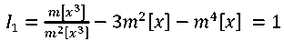 (3)
(3)
Based on equation (3), we obtain several expressions for determining the degree of deviation of the AE pulse flow from the Poisson one (4)–(7):
 (4)
(4)
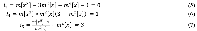
The construction of invariant dependences based on formulas (3)–(7) is produced by an experimentally developed hardware-software complex (HSC) (Fig. 4), which provides multi-channel registration, processing and analysis of the values of loads and deformations; video surveillance and recording of the test process and the readings of analog devices using video cameras.
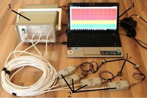
Fig. 4. Hardware-software complex of acoustic-emission diagnostics:
1 — highly sensitive piezoelectric sensor GT-300; 2 — vibroacoustic signal preamplifiers; 3 — analog-to-digital converter; 4 — PC for data processing
Highly sensitive piezoelectric sensors GT-300 are installed on the controlled surface of the CM. Informative parameters on the state of the CM from piezoelectric sensors are transmitted to the preamps of the vibroacoustic signal2. After amplification, the signal is sent to an analog-to-digital converter, in which it is converted from mechanical to electrical work. The PC is used for clustering and processing of received data.
Research Results. With the help of the HSC and RM-1 tensile testing machine, CMU-1 carbon fiber used in the production of the IL-96-300 aircraft and the Orion UAV was monitored at the Centre. The major characteristics of CMU-1 are given in Table 4.
Table 4
CMU-1 carbon fiber specification

For testing, CMU-1 was placed in a tensile testing machine, having previously installed AE GT-300 sensors on CM. CMU-1 was loaded using the HSC. The loading results are shown in Figure 5 (a, b, c):
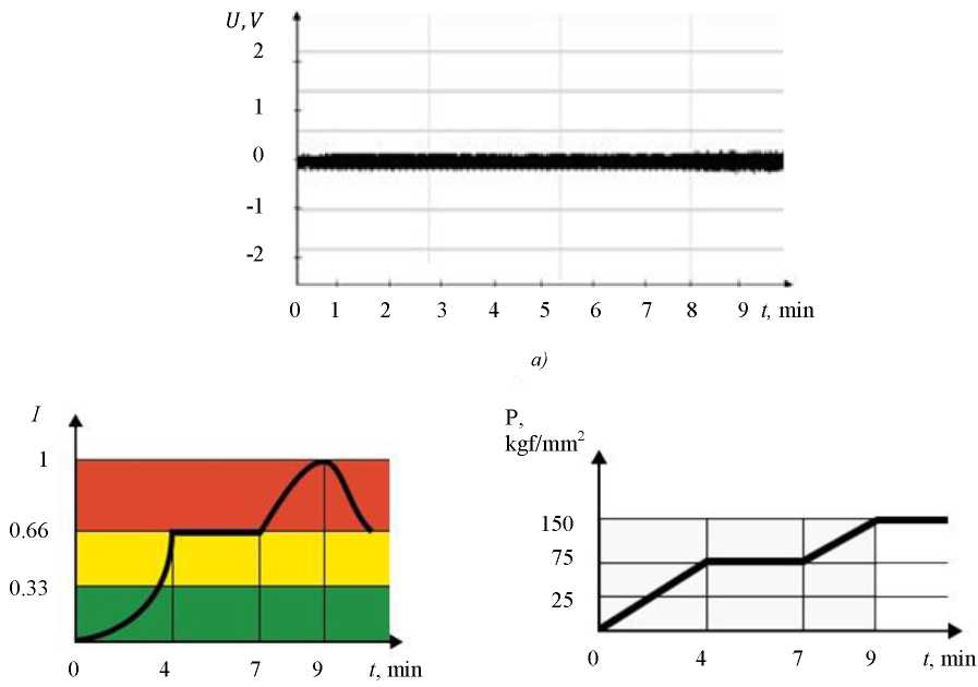
Fig. 5. CMU-1 loading results: a) oscillogram of AE CMU-1 signals; b) mode of APC operation; c) loading dynamics projection of RM-1 CM CMU-1
Figure 5 a shows the oscillogram of CMU-1 AE signals. The maximum value of the AE OC amplitude corresponds to the destruction of the OC matrix and fibers (𝑈max = 0.25 V).
Figure 5 b shows the HSC operation mode. Three zones are highlighted here — red, yellow, and green. The red zone is characterized by the presence of pronounced CMU-1 defects. The numerical value of the invariant ranges from 0.66 to 1 at t = 7–9 min. This indicates a critically active defect — the stage of destruction. The yellow zone is the zone of the active defect and the stage of crack formation (I=0.33–0.66; t = 4–7 min). Green is a benign zone that characterizes the stage of microcracks (I=0–0.33; t = 9–4 min) [12][13].
Figure 5 c shows the projection of the loading dynamics of RM-1 CM CMU-1. Due to an increase in the load (𝑃 = 25,75,150 kgf/mm2) the value of the invariant and amplitude of the AE CMU-1 increases.
Discussion and Conclusions. The use of CM is a promising method of assessing the technical condition under designing various aircraft and UAVs. One of the fundamental advantages of CM is the lightening of the structure mass in comparison to traditional materials. Monitoring and evaluation of the technical condition of aircraft and UAVs should be carried out by advanced NDT methods that can identify various kinds of defects at an early stage of their development. The acoustic emission method meets these requirements. In the future, it is possible to install a prototype of a hardware and software complex on the fifth-generation multipurpose fighter Su-57 to diagnose the design of the aircraft in flight. This acoustic emission system will provide identifying defects that occur in the structural elements of the aircraft at a small stage of their development. The experimentally developed sample of the hardware and software complex enables to quickly register in real time the developing defects of aviation materials used in the design of aircraft and unmanned aerial vehicles.
1. Ferrozondovyi metod nerazrushayushchego kontrolya detalei vagonov. Rukovodyashchii dokument RD 32.149. Moscow: Federal Agency for Technical Regulation and Metrology; 2008. 163 p. (In Russ.)
2. Popov AV. Sposob otsenki protsessov razrusheniya konstruktsii pri akustiko-ehmissionnom kontrole. RF patent no. 223444, 2004. (In Russ.)
1. Волоконные композиционные материалы: пер. с англ. / Под ред. Дж. Уитона, Э. Скала. — Москва: Металлургия, 2011. — 240 с.
2. Григорович, В. К. Дисперсионное упрочнение тугоплавких металлов / В. К. Григорович, Е. Н. Шефтель. — Москва: Наука, 1980. — 303 с.
3. Ермоленко, И. Н. Волокнистые высокотемпературные керамические материалы / И. Н. Ермоленко, Т. М. Ульянова. — Минск: Наука и техника, 1991. — 125 с.
4. Степанова, Л. Н. Использование метода акустической эмиссии при циклических испытаниях композиционных элементов авиационных конструкций / Л. Н. Степанова, В. Н. Чаплыгин, Е. Ю. Лебедев // Контроль. Диагностика. — 2004. — № 12. — С. 53.
5. Буйло, С. И. Диагностика стадий разрушения материалов по восстановленным параметрам потока актов акустической эмиссии / С. И. Буйло // Контроль. Диагностика. — 2000. — № 10. — С. 10–15.
6. Чуи, Ч. Введение в вейвлеты / Ч. Чуи. — Москва: Мир, 2001. — 412 с.
7. Muravin, B. Guide for Development of Acoustic Emission Applications for Examination of Metal Structure / Boris Muravin, Mark F. Carlo // Journal of Acoustic Emission. — 2011. — Vol. 29. — P. 142–148.
8. Blind deconvolution of acoustic emission signals for damage identification in composites / Gangtie Zheng, M.A. Васkle, G. Kister, Gerard F. Fernando // AIAА Journal. — 2001. — Vol. 39. — Р. 1198–1205. https://doi.org/10.2514/2.1435
9. Skalskyi, V. R. Some methodological aspects of application of acoustic emission / V. R. Skalskyi, P. M. Koval. — Lviv: Spolom; 2007. — 336 p.
10. Maochen Ge. Analysis of Source Location Algorithms, Part I: Overview and non-iterative methods / Maochen Ge // Journal of Acoustic Emission. — 2003. — Vol. 21. — P. 14–28.
11. Barat, V. Detection of AE signals against background friction noise / V. Barat, D. Grishin, M. Rostovtsev // Journal of Acoustic Emission. — 2011. — Vol. 29. — P. 133–141.
12. Попов, А. В. Метод контроля прочности силовых элементов конструкций на основе оценки численно-временных характеристик АЭ процессов / А. В. Попов, Е. А. Кондрашин // Контроль. Диагностика. — 2008. — № 7. — С. 45–46.
13. Попов, А. В. Определение прочностных характеристик конструкций на основе амплитудных инвариантов акустико-эмиссионных процессов / А. В. Попов, В. Э. Жумай // Контроль. Диагностика. — 2008. — № 10. — С. 29–31.
Voronezh
Voronezh
Voronezh
Popov A.V., Samuylov A.O., Cherepanov I.S. Application and evaluation of the technical condition of composite materials in aircraft and unmanned aerial vehicles by acoustic emission method of nondestructive testing. Advanced Engineering Research (Rostov-on-Don). 2021;21(4):328-336. https://doi.org/10.23947/2687-1653-2021-21-4-328-336


Advanced Engineering Research (Rostov-on-Don)
ISSN 2687-1653 (Online)
Contact with: Publisher / Editorial Office of the Journal
Publisher: Don State Technical University - DSTU, Rostov-on-Don, Russia - https://donstu.ru/en/
Editor-in-Chief: Alexey N. Beskopylny, Dr.Sci. (Eng.), Professor, Vice-Rector, Don State Technical University (Rostov-on-Don, Russia)
Don State Technical University
1, Gagarin Sq., Rostov-on-Don, 344003, Russia
tel.: +7 (863) 2738-372, e-mail: vestnik@donstu.ru
16+
Processing of personal data


