


Contents
Scroll to:
https://doi.org/10.23947/2687-1653-2021-21-4-337-345
Scroll to:
Introduction. The paper submits the analysis of existing design solutions of flow dividers used to synchronize hydraulic drives of working bodies of technological and mobile machines. The market demands for multithreaded throttle flow dividers without valves with the controlled division ratio, such as multi-axle vehicle chassis, are identified. The objective of the work was to analyze the possibility and rationale for developing a throttle four-way flow divider without valves with sensing elements of the Venturi tube type. The solution should provide the synchronicity of movement (rotation) of more than three working bodies of technological and mobile machines.
Materials and Methods. A patent search for the designs of hydraulic flow dividers is carried out, and systems that require the division of the hydraulic fluid flow into more than two executive bodies are considered. An upgrade option, which allows dividing the flow into four branches, is proposed for the design of a three-channel throttle flow divider without valves.
Results. The urgency of developing a multithreaded throttle flow divider without valves for application in industrial and mobile machines is validated. Two types of four-flow dividers are considered, their weaknesses are indicated. It is noted that the development of a multithreaded throttle flow divider based on the designs created in 1989 and 1991 will reduce the number of hydraulic pumps and get rid of the series connection of double-flow dividers. In this way, it is possible to reduce pressure losses in the hydraulic system and implement adaptive control of hydraulic motors of multi-motor mobile machines. The possibility to obtain a divider/combiner into four flows by adding an outlet chamber connected to the membrane chamber through a channel entering the Venturi nozzle on the basis of a three-flow throttle divider is shown. The principle of operation of such equipment is described.
Discussion and Conclusions. The principles of construction of throttle flow dividers without valves are considered. An upgrade option is proposed to increase the number of division channels from three to four. However, to validate the operability of this design, a numerical analysis of the various modes of operation of the divider is required — calculation of the reduced volumetric stiffness of its working cavities. The information obtained can be used to modernize the hydraulic units of technological and mobile machines, increase their reliability, manufacturability, and efficiency. The issues that need to be solved in further research are identified.
Rybak A.T., Ivanovskaya A.V., Batura P.P., Pelipenko A.Yu. Synchronization in multi-motor hydromechanical systems. Advanced Engineering Research (Rostov-on-Don). 2021;21(4):337-345. https://doi.org/10.23947/2687-1653-2021-21-4-337-345
Introduction. The condition of absolute synchronization is compliance with the proportionality of linear and angular displacements of hydraulic motors and all time derivatives of them. It is often required to synchronize:
— homogeneous linear or rotational movements of two or more hydraulic drives,
— one engine with the turn of the second.
In machine tool and mechanical engineering, when synchronizing drives, it is critical to consider the position synchronization errors. The paper discusses ways of synchronizing hydraulic motors in multi-motor systems with a flow divider, as well as examples of the application of such systems in industry. In addition, the use of a multithreaded throttle flow divider without valves as a synchronizing device of a multiaxial wheel coupling of a hydraulic transport platform is discussed.
Fundamental works on hydromechanical systems have been known since antiquity. The earliest surviving one is Archimedes' treatise “On Floating Bodies”. Today, the use of complex multi-level and branched hydraulic systems is sufficiently investigated, but the issue of control and regulation in a hydraulic drive to increase its efficiency and reduce the size of the system remains relevant1 2 [1–4].
The category of complex hydraulic systems includes those where one hydraulic pump feeds two or more independent hydraulic motors. At the same time, regardless of the load on the output links, the synchronicity of their movements must be provided. The required synchronization accuracy determines the selection of its method. The simplest one is the provision of rigid mechanical coupling of hydraulic motors. However, for systems with a complex arrangement of executive bodies in space, it is not applicable. The most common methods are:
— by shaft-coupled hydraulic motors or hydraulic pumps (volumetric synchronization);
— through series connection of cavities of hydraulic motors;
— by hydraulic tracking systems with distributors and hydrotachometers;
— by hydromechanical and electrohydraulic tracking systems.
The most practicable and simple means of synchronization in mobile machines and technological equipment are throttle dividers and flow dividers/combiners 3 4 [5−8]. A hydraulic flow divider separates one working fluid flow into two or more. In this case, the specified ratio is taken into account, and it is required to provide synchronous (coordinated) movement of the output links regardless of their load. The flow divider/combiner acts similarly to the divider, but in the opposite direction. It is easily integrated into the hydraulic system, and it is cheap and easy to operate. A flow divider/combiner provides synchronization in a wide range of speeds of movement of output links of hydraulic motors.
In the classical design of the throttle divider, spool-and-sleeve valves are used as a shut-off-and-regulating element [5]. This causes the characteristic disadvantages of such dividers. Specifically, the high cost of precision spooland-sleeve valves is due to the complexity of manufacturing, and a large share of such high-precision operations as honing, grinding, electrical discharge machining. Selective assembly and fine-tuning of spool-and-sleeve valves makes them practically non repairable, which also increases their operational cost. The above also indicates the susceptibility of the system to the quality of hydraulic fluid, which is subject to very high requirements [6].
There are known attempts to design dividers without spool-and-sleeve valves 5 6 7 8. The possibilities of improving the characteristics of spool dividers were investigated. It should be noted that the listed designs of flow dividers provide synchronization of only two actuators, and this significantly narrows the scope of their application. The objective of this study is to search for a promising design of a multithreaded throttle divider that meets the requirements of the operation of mobile machines.
Multi-motor hydromechanical systems. Hydraulic systems are known, which include more than two working bodies (both reversible and non-reversible). Depending on the operating conditions, they require constant or short-term synchronicity of movement with a constant or variable speed ratio. Such systems, in particular, include:
— travel hydraulic drives of mobile machines,
— pulling presses for large sheet metal,
— stamping machines for dimensional parts,
— groups of hydraulic jacks for lifting the building footings,
—rudder folding hydraulic drives in aerospace engineering,
— positioning systems of the radio reflector petals.
The application of well-known throttle flow dividers without valves in such systems undoubtedly improves operational characteristics. At the same time, the number of synchronized working bodies is limited to two per one flow divider. This limitation stimulates designers to use sequential cascading of flow dividers. As a result, pressure losses (up to 30 %) increase at the output of the division cascades, and the synchronization error of each divider is summed up. It is also important to increase the volume occupied by hydraulic equipment. In general, this approach is technically unjustified and financially costly.
In this regard, it is worth noting the diaphragm flow divider design 9. It can be used in reversible hydraulic systems in which it is required to dynamically change the ratio of execution speeds. In addition, this design enables to create a divider into 3, 4 or more independent flows based on it 10.
We consider the application of a throttle flow divider without valves using the example of a hydrostatic wheel drive transmission of multi-axle transport chassis.
To design transmission systems of modern all-wheel-drive vehicles, as a rule, a locked and differential circuit is used. The locked transmission provides a rigid connection of the drive wheels. The differential one is characterized by the branching of one incoming power flow between the drive axles and wheels through a special differential node. There are also combined transmission schemes in which one part of the wheels is connected by a differential coupling, and the other is locked (e.g., locking of several differentials). For transmission systems, forced adjustment of:
— the power supplied to one or more wheels,
— one axle independently of the others, is not possible.
The presence of a hydraulic drive chassis in the transmission system enables to individually supply power to the wheels and provides stepless regulation in a wide range of values. The hydraulic drive design is compact, resistant to external atmospheric influences. In addition, the hydraulic drive, as a rule, has a large range of regulation, which is important for an off-road vehicle. Another advantage of the hydro-volume wheel drive is the capability to quickly reverse. This is important when swinging over obstacles. The hydrostatic wheel drive provides continuous movement at minimum speed with high tractive effort, which also increases the vehicle’s off-road performance.
The hydraulic scheme of the undercarriage for one axis of such a machine is generally shown in Fig. 1.
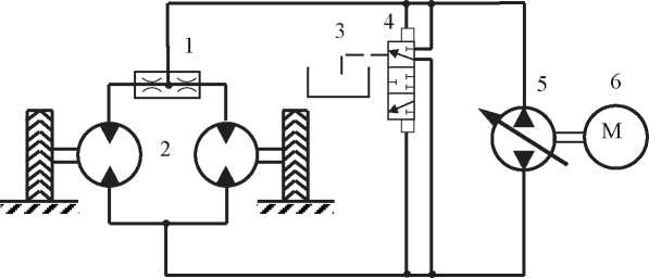
Fig. 1. Hydraulic diagram of one wheel axle of a mobile transport machine
Consider the system of hydrostatic transmission. The internal combustion engine 6 transmits torque to the reversible hydraulic pump 5, which is connected by pipelines and the hydraulic distributor 4 with a flow divider 1 and hydraulic motors 2. The shafts of the hydraulic motors are connected to the drive wheels. Often, axial-piston or radialpiston hydraulic motors are structurally connected to the wheel. This arrangement forms a single “hydraulic motor — wheel” node. Under the engine operation, the hydraulic pump provides the hydraulic motors of the drive wheels with hydrodynamic fluid pressure, which is further converted into mechanical work. Depending on the design of the hydraulic units, the operating pressure in the system is in the range of 25–50 MPa. The operation of the “hydraulic motor — wheel” unit increases the passability of the chassis as a result of a continuous flow of power and a smooth change in torque.
Scheuerle and Kamag (Germany) produce modular hydraulic transport platforms: medium — FlatCombi K22, and heavy self-propelled — InterCombi K25 (Fig. 2).
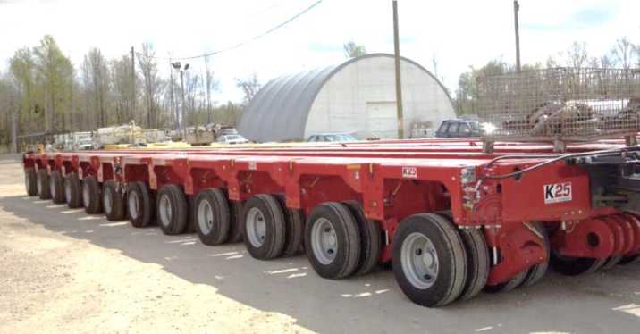
Fig. 2. Two connected 6-axis self-propelled InterCombi K25 modules from Kamag (Germany)
The modules of the medium series with a width of 2,750 and 3,000 mm are designed for a load of 23 and 25 tons per axle at speeds up to 10 km/h. Heavy series modules are equipped with 2–6-wheel axles. The width of the platform is 3,000 and 3,100 mm, the load on one axle is 36–45 tons. Self-propelled modules are driven by PowerBooster power plants. Options for combining them are as follows:
— one platform on which a bridge structure is laid,
— two turntable trolleys.
In the domestic engineering industry, it is possible to distinguish a promising design of a multiaxial, fully hydraulic chassis developed by the Central Research and Development Automotive and Automotive Engine Institute “NAMI”. This is “Gidrokhod-49061” 11, a three-axle vehicle (Fig. 3).
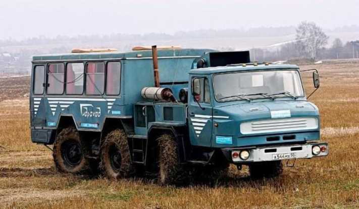
Fig. 3. “Gidrokhod-49061”, NAMI vehicle
The design of this machine implements the idea of a “"flexible wheel drive”, which provides an individual hydraulic pump for each of three wheel axles. The conveyor is built on the basis of ZIL-4906 chassis. Equipping the chassis with a hydrostatic transmission enables to implement all possible types of wheel transmissions: locked, differential, with independent control, as well as their combinations. The industry is interested in developing the production of volumetric-hydraulic wheeled cross-country chassis, which stimulates new research in this area.
Flow dividers are widely used in hydraulic transmission circuits to provide differential locking, which increases the passability of obstacles. The flow divider ensures that both synchronized wheels will always generate traction, even if one of them is on soft or slippery ground. But for synchronization and flow control in a 4- and 6-axis design, several dividers must be connected in series, and with a variable division ratio according to the control signal.
Research Results. The considered four-threaded dividers can be attributed to one of two types. In the first case, we are talking about units with a spool. This is a cascade of three flow dividers in one housing. An example is the Poclain FD-M412 flow divider (France). Figure 4 shows its physical form and hydraulic circuit.
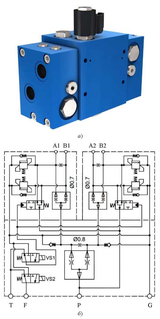
Fig. 4. Four-way flow divider Poclain FD-4M: a) appearance, b) hydraulic circuit diagram
In designs of the second type, it is not possible to change the division ratio by an external control signal. This limits the scope of application of dividers in controlled multi-motor hydraulic systems. The development of a multi-way throttle flow divider based on the designs created in 1989 and 199113 14, will reduce the number of hydraulic pumps and get rid of the serial connection of two-flow dividers (respectively, reduce pressure losses in the hydraulic system), as well as implement adaptive control of hydraulic motors of multi-motor mobile machines [7].
Thus, e.g., it is possible to obtain a divider/combiner into four flows (Fig. 5) by adding the outlet chamber 16 connected to the membrane chamber 10 through a channel entering the Venturi tube nozzle 3. In this case, the left chambers 15, 16 and right chambers 17, 18 can be connected by a movable plunger 13 between chambers 16 and 17.

Fig. 5. Four-flow divider with sensitive elements of the Venturi tube type
We describe the principle of operation of a flow divider/combiner with sensitive elements in the form of Venturi tubes. During the flow division, the working fluid is directed to the input of the divider/combiner 1. Then the flows are divided between the sensing elements 2, 3, 4 and 5. They are made in the form of Venturi tubes, and their necks are connected to adjacent working chambers 6, 7, 8 and 9. In this case, chambers 6, 7 and 8, 9 are the executive elements of the structure. They are separated from each other by membranes 10 and 11 and are rigidly fixed in the body of movable plungers 12 and 14. The movable plunger 13 provides connection between the left and right parts of the divider. After the Venturi tubes, the fluid flows pass through the axial and radial bores of plungers 12 and 13, and then fall on the variable resistances 15, 16 and 17, 18 and to the output channels 19, 20 and 21, 22.
Assume that hydraulic motors on all branches are under the same load. Accordingly, the flows in the branches are the same, and, therefore, the flows through the corresponding Venturi tubes are the same. In the necks of the Venturi tubes there will be the same high-speed pressures, so the pressures in the control chambers will also be equal. The pressure on the walls of the membrane elements of the actuators will be the same on both sides, and this will bring them into a balanced state.
If the load increases (e.g., on a hydraulic motor connected to the outlet channel 19), the flow rate in the corresponding branch and the Venturi tube 2 connected to it will decrease. As a result, the high-speed pressure in its neck will decrease, which means that the pressure in it will increase. In turn, this will cause an increase in pressure in the working chamber 6. As a result, the equilibrium of the membrane 10 is disturbed, and it will shift to the right. Plunger 12 will also move to the right, narrowing the free area of the variable resistances 16 and 17, which are connected to the resistance 16 through the movable plunger 13. As a result, the flow in the corresponding branches and Venturi tubes 3 and 4 will decrease. Just as before, plunger 14 will start moving to the right and reduce the free area of the variable resistance 18. This process will continue until the flows are balanced in all branches of the divider.
In the summation mode, the flows for combining are fed to the output channels of the divider/combiner, and its workflow is reversed.
It is worth noting that even at the development stage, it is required to know the reliability and functional properties of the proposed design of the divider/combiner. The best ways to obtain the required data are modeling and numerical experiments15 [9–13].
Discussion and Conclusions. The widespread application of multi-motor branched hydraulic systems in the industrial and mobile equipment often involves the synchronization of their actuators. Depending on the operating conditions and functional requirements, solutions based on complex designs of adjustable volumetric hydraulic machines or throttle flow dividers are used [5–8]. In cases where it is needed to use the matching mechanism for a short time, the most economical way of synchronization, in our opinion, is to apply a throttle flow divider. The considered hydraulic machines (Fig. 2, 3) fully correspond to the concept of a multi-motor hydraulic system. The application of throttle flow dividers in the design of the driving wheel axles of such machines will provide the implementation of a differential circuit without a mechanical transmission. This will increase the off-road performance and enable to effectively control the hydraulic drives of the wheelset.
There are no multi-way throttling controllable flow dividers on the market. This indicates the demand for their development.
Further work on the design of the four-flow divider/combiner described in the paper will be aimed at creating a mathematical model. Its basis will be the fundamentals of the theory of volumetric rigidity16 17 18 [14–16]. This will revise the physical dimensions of the elements of the divider/combiner and calculate the permissible operating modes.
1. Urekin VS, Istomina YV. Development of hydraulic automatic control system drives of technological equipment. In: Proc. II All-Russian Sci.-Tech. Conference. Penza: Mezhotraslevoi nauch.-inf. Tsentr; 2016. P. 259–262. (In Russ.)
2. Lazuta IV, Lazuta EF. Nonlinear correlation of the relay automatic control system of the hydraulic drive. In: Proc. National Sci.-Pract. Conference: Education. Transport. Innovation. Omsk: SiBADI; 2018. P. 64–69. (In Russ.)
3. Yatsukhin YuA. Issledovanie gidravlicheskoi sistemy sinkhronizatsii dvizheniya rabochikh organov sel'skokhozyaistvennykh mashin: Cand.Sci. (Eng.), diss., author’s abstract. Rostov-on-Don; 1972. 25 p. (In Russ.)
4. Rybak AT. Izyskanie ratsional'nogo tipa zaporno-reguliruyushchego ehlementa drossel'nogo delitelya potokov gidroprivodov sinkhronnykh mekhanizmov sel'skokhozyaistvennykh mashin: Cand.Sci. (Eng.), diss., author’s abstract. Rostov-on-Don; 1989. 23 p. (In Russ.)
5. Kirikov RP, Sherman EB, Kuzik VL, et al. Flow divider. USSR Patent, no. 1041773, 1983. (In Russ.)
6. Flow divider: France Patent no. 1566897, 1970. (In Russ.).
7. Rybak AT, Yatsukhin YuA, Negodov VN, et al. Throttle flow divider. USSR а. с. 1151725, 1985. (In Russ.).
8. Flow divider: US Patent no. 10578221, 2020.
9. Yatsukhin YuA, Kolosov LP, Rybak AT. Throttle flow divider. USSR Patent no. 1670191, 1991. (In Russ.).
10. Rybak AT, Yatsukhin YuA, Antonenko VI. Multithreaded flow divider/combiner. USSR Patent no. 1742530, 1992. (In Russ.).
11. Prochko EI. Metody postroeniya sistem silovykh gidroob"emnykh privodov koles polnoprivodnykh avtomobilei: Cand.Sci. (Eng.), diss., author’s abstract. Moscow; 2007. 20 p. (In Russ.)
12. POCLAIN Hydraulics product catalog. POCLAIN Hydraulics. URL: https://www.poclainhydraulics.com/_upload/ressources/media/pdf/B33971Z.pdf (accessed 18.01.2021).
13. Yatsukhin YuA, Kolosov LP, Rybak AT, et al. Throttle flow divider. USSR Patent no. 1670191, 1991. (In Russ.)
14. Rybak AT, Yatsukhin YuA, Antonenko VI. Multithreaded flow divider/combiner. USSR Patent no. 1742530, 1992. (In Russ.)
15. Rybak AT. Modelirovanie gidravlicheskikh sistem na osnove teorii ob"emnoi zhestkosti. In: Proc. Int. Sci.-Pract. Conf. Divnomorskoe: DSTUPrint; 2017. P. 234–242. (In Russ.)
16. Mirnyi VI. Povyshenie ehffektivnosti bystrodeistvuyushchego gidravlicheskogo privoda vozvratno-postupatel'nogo dvizheniya: Cand.Sci. (Eng.), diss., author’s abstract. Rostov-on-Don; 2008. 21 p. (In Russ.)
17. Zatolokin SA. Sovershenstvovanie teorii i metodov proektirovaniya gidromekhanicheskikh sistem s nasosno-akkumulyatornym istochnikom raskhoda postoyannogo davleniya: Cand.Sci. (Eng.), diss., author’s abstract. Rostov-on-Don; 2009. 18 p. (In Russ.)
18. Ust'yantsev M. V. Povyshenie ehffektivnosti privoda stenda ispytanii gidromashin vrashchatel'nogo deistviya: Cand.Sci. (Eng.), diss., author’s abstract. Rostov-on-Don; 2012. 18 p. (In Russ.)
1. Симанин, Н. А. Адаптивное управление гидравлическим приводом металлорежущего станка / Н. А. Симанин, В. В. Коновалов, Ю. В. Родионов // Вестник Тамбовского государственного технического университета. — 2017. — Т. 23, № 2. — С. 338–347. DOI: 10.17277/vestnik.2017.02
2. Гидравлическая стабилизация нагруженных высокоскоростных пневматических приводов / В. А. Королев, И. Л. Коробова, С. М. Стажков, Б. Н. Воротынцев // Мехатроника, автоматика и робототехника. — 2019. — № 4. — С. 34–38. https://doi.org/10.26160/2541-8637-2019-4-34-38
3. Селиванов, А. М. Принцип комбинированного регулирования скорости выходного звена гидравлического привода и его современная реализация / А. М. Селиванов // Вестник Московского авиационного института. — 2011. — Т. 18, № 3. — С. 147–151.
4. Сунарчин, Р. А. Неустойчивость и автоколебания в гидравлических следящих приводах / Р. А. Сунарчин, М. А. Машков, А. В. Матросов // Динамика и виброакустика. — 2018. — Т. 4, № 3. — С. 16–25. https://doi.org/10.18287/2409-4579-2018-4-3-16-25
5. Скрицкий, В. Я. Синхронизация исполнительных органов гидрофицированных машин и механизмов / В. Я. Скрицкий, В. А. Рокшевский. — Москва : Машиностроение, 1973. — 140 с.
6. Рыбак, А. Т. Дроссельные делители и делители-сумматоры потоков синхронных гидросистем мобильных машин и технологического оборудования / А. Т. Рыбак // Вестник Донского государственного технического университета. — 2005. — Т. 5, № 2. — С. 179–188.
7. Рыбак, А. Т. Дроссельные делители и делители-сумматоры потоков для разветвленных гидравлических систем / А. Т. Рыбак // Вестник Донского государственного технического университета. — 2005. — Т. 5, № 1 (23). — С. 28–35.
8. О перспективных направлениях создания гидравлических агрегатов приводов строительных и дорожных машин / В. А. Коробкин, А. Я. Котлобай, А. А. Котлобай, В. Ф. Тамело // Наука и техника. — 2012. — № 6. — С. 71–76.
9. Kobzev, K. Learning the basics of a battery pack control system / K. Kobzev, S. Vyalov, A. Rybak // E3S Web of Conferences. — 2020. — Vol. 164. — P. 13006. https://doi.org/10.1051/e3sconf/202016413006
10. Khinikadze, T. Simulation of the hydraulic system of a device with self-adaptation by power and kinematic parameters on the working body / T. Khinikadze, V. Pershin, Y. Karagodskaya // IOP Conference Series: Materials Science and Engineering. — 2020. — Vol. 1001. — P. 012061. DOI: 10.1088/1757-899X/1001/1/012061
11. Ивановская, А. В. Обоснование применения гидравлического привода, чувствительного к изменению нагрузки / А. В. Ивановская, Е. В. Богатырева, В. В. Попов // Вестник Керченского государственного морского технологического университета. — 2018. — № 1. — С. 62–68.
12. Pilipenko, S. S. Hydraulic transmission-multiplier drive with dosing modules / S. S. Pilipenko, M. R. Baiguzin, A. P. Potapenkov // Steel in Translation. — 2016. — Vol. 46. — P. 705–710.
13. Bidirectional synchronization control for an electrohydraulic servo loading system / Yong Sang, Weiqi Sun, Fuhai Duan, Jianlong Zhao // Mechatronics. — 2019. — Vol. 62. — P. 102254. DOI: 10.1016/j.mechatronics.2019.102254
14. Vanin, V. A. Stepper hydraulic motor with pneumatic (jet) control system in machines with hydromechanical forming links / V. A. Vanin, A. N. Kolodin, A. A. Rodina // Journal of Physics: Conference Series. — 2019. — Vol. 1278. — P. 012019. DOI: 10.1088/1742-6596/1278/1/012019
15. Приведенная объемная жесткость гидравлических систем / В. П. Жаров, А. Т. Рыбак, С. А. Затолокин, В. И. Мирный // Вестник Донского государственного технического университета. — 2008. — Т. 8, № 4 (39). — С. 177–185.
16. Першин, В. А. Методика функциональной унификации адаптивного модуля гидропривода с функцией стабилизации нагрузки на рабочем органе мобильных машин / В. А. Першин, Т. А. Хиникадзе // Вестник Донского государственного технического университета. — 2018. — Т. 18, № 3. — С. 319−326. https://doi.org/10.23947/19925980–2018–18–3–318–325
Rostov-on-Don
Kerch
Rostov-on-Don
Rostov-on-Don
Rybak A.T., Ivanovskaya A.V., Batura P.P., Pelipenko A.Yu. Synchronization in multi-motor hydromechanical systems. Advanced Engineering Research (Rostov-on-Don). 2021;21(4):337-345. https://doi.org/10.23947/2687-1653-2021-21-4-337-345


Advanced Engineering Research (Rostov-on-Don)
ISSN 2687-1653 (Online)
Contact with: Publisher / Editorial Office of the Journal
Publisher: Don State Technical University - DSTU, Rostov-on-Don, Russia - https://donstu.ru/en/
Editor-in-Chief: Alexey N. Beskopylny, Dr.Sci. (Eng.), Professor, Vice-Rector, Don State Technical University (Rostov-on-Don, Russia)
Don State Technical University
1, Gagarin Sq., Rostov-on-Don, 344003, Russia
tel.: +7 (863) 2738-372, e-mail: vestnik@donstu.ru
16+
Processing of personal data


