


Contents
Scroll to:
https://doi.org/10.23947/2687-1653-2022-22-2-91-98
Scroll to:
Introduction. The paper presents a brief kinematic analysis, as well as the application of D'Alembert's principle to finding the relationship between the force parameters in the transmission mechanism of a robotic manipulator constructed from a twisted arm chain. The use of this transfer mechanism can enhance the life of the arm actuator, the accuracy of its positioning, and increase the workload compared to the flexible linkage actuators (twisted strings). The work aimed at obtaining dependences between the displacements of circuit elements, as well as their force parameters required to monitor the control system operation of these devices.
Materials and Methods. In the course of solving the problem, an elementary segment (element) of the transmission chain was considered. To find the relationship between the loads in the element, the virtual displacement principle was used. When finding kinematic connections between displacements, a brief geometric analysis of the transmission chain element was carried out. To conduct a comparative analysis of the analytical dependences obtained, a simulation technique implemented on a graphical link model using the NX software package was applied.
Results. In the course of the study, we obtained dependences for determining the magnitude of the moment developed on the input link, depending on the external workload and its rotation angle, as well as for defining the linear displacement of the output link. A simulation model of the actuator was constructed, which can be applied in the dynamic study of the actuator mechanism, taking into account the inertia of the links.
Discussion and Conclusions. From the obtained analytical dependences, we determined the value of the angle of rotation of the input link of the mechanism element, at which the maximum torque value for a fixed workload on the output element was achieved, as well as the maximum linear displacement of the output link. The calculated values were in good agreement with similar values obtained from the results of the simulation experiment, which gave us the possibility of using analytical dependences in the formation of a robot control system. In addition, these dependences made it possible to provide the selection of actuators with the required force indicators.
Bondarenko I.R., Voloshkin A.A., Perevuznik V.S., Kovalev L.A. Calculation of the force and kinematic parameters of the transfer mechanism based on a twisted arm chain. Advanced Engineering Research (Rostov-on-Don). 2022;22(2):91-98. https://doi.org/10.23947/2687-1653-2022-22-2-91-98
Introduction. Recently, devices based on twisting cables or strings (threads) have begun to gain popularity. These inventions are universal in use and are in demand in various areas of robotics, specifically, in the manufacture of manipulators, grippers and exoskeletons1 [1−4]. Drive structures based on twisting flexible elements have a number of advantages. These include the size of the device, ease of assembly and installation, versatility. As an example, a mechatronic twisted actuator, which is an electromechanical device with numerical control, is able to independently monitor the state of the working body based on data obtained from the shaft position sensor and the force sensor.
In the presented work, the authors carried out a kinematic and power analysis of the transmission mechanism of the actuator, built on the basis of a twisted arm chain. This design is intended to replace actuators using flexible transmission links, namely, twisting cables and strings.
The experimental device shown in Figure 1 consists of an electric motor and several strings oriented along the motor rotation axis. Strings connect the motor drive shaft to the simulated load generated by another electric actuator. Load control (linear actuator) enables to consider this system as a spring damper with adjustable parameters.
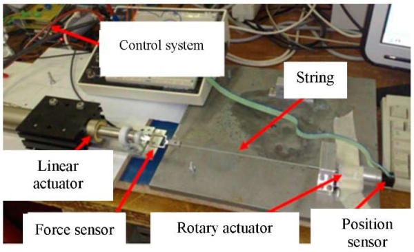
Fig. 1. Experimental setup [4]
Thanks to the string-twisted actuator, it was possible to place all the drives and motors in the prosthetic arm, given that all the main degrees of mobility of the arm were provided [5−8]. At the same time, the weakest point of the system is a flexible cable or string. Wear and stretching of the twisting string are the key disadvantages of this type of actuators.
An alternative solution to this problem may be the replacement of twisted strings or cables with a chain link system. Let us replace a fragment of twisted strings or cables with an element (segment) of rigid levers (rods) that pivotally connect two circles with radius R and centers O1 and O2 (Fig. 2 а). Input link 1 is supported by thrust bearing 6 and has the possibility of rotational movement relative to center O1, located on ZO axis. In this case, lower circle 4 (the output link) can make a translational movement along ZO axis due to the presence of guide 5. As a result of rotation of the upper circle, levers 3 and 4 perform spherical motion relative to link 1, thereby changing distance l and moving workload P (Fig. 2 b, c).
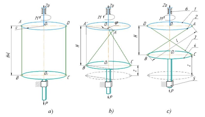
Fig. 2. Diagram of the actuator chain segment:
а — in initial position;
b — in intermediate position;
c — in limit position
For the practical implementation of this design solution, it is required to have a control system based on a mathematical model of the actuator, which reflects the kinematic and power connections between the elements of the actuator chain.
This work aimed at finding kinematic and power connections in an elementary segment of the actuator chain.
Materials and Methods. We propose to find the solution to this problem using the virtual displacement principle [9], which enables to exclude internal forces in the links of the actuator element from consideration. Thus, the torque applied to the input link remains under consideration, as well as workload P applied to the output link. Considering the scheme shown in Fig. 4 b, we take rotation angle φ as the generalized coordinate for the input link, and linear displacement z — for the output link [10].
In accordance with the virtual displacement principle [11], we make up the equation of works:
 (1)
(1)
where δφ — rotational virtual displacement of the input link, δz — linear virtual displacement of the output link
Distance H between links 1 and 2 is related to the linear displacement z of link 2, taking into account the length of the lever AB = l, dependence H = l – z. Then, taking into account the scheme shown in Figure 4 b, we can write:
Value z, depending on the rotation angle φ, is defined as:
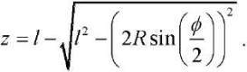 (2)
(2)
According to [11], the relationship between virtual displacements can be established as:
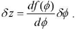
Then, taking derivative  from (2) and performing the transformations, we get the dependence between the virtual displacements
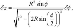
Substituting δz into the equation of works (1), we obtain:
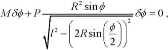
whence, through reducing by δφ, we express moment M as rotation angle function φ in the form:
 (3)
(3)
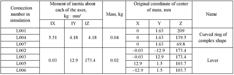
To evaluate the obtained analytical dependences of moment (3) developed at the input link and the linear displacement of the output link from the angle of rotation (2), a simulation experiment was carried out [12][13], implemented in the NX Nastran software environment [14]. For this purpose, a three-dimensional solid-state model of a section of the actuator chain (Fig. 3 a), consisting of two sequentially connected elementary segments of the mechanism under study, was constructed. One of the segments of the actuator (Fig. 3 b) was used to perform the calculation with the following parameters: R = 12 mm, l = 54 mm. When constructing the model, spherical joints were presented in the form of toroidal joints, which made it possible to perform chain elements in the form of curved rings connected by rigid levers (Fig. 3). This design allows the levers to perform spherical movement. Since this connection provides the levers with the required degree of freedom, it can be considered corresponding to a spherical joint (Fig. 5 c).
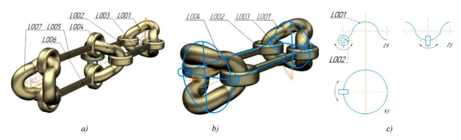
Fig. 3. Three-dimensional solid models:
a — chain section of two segments;
b — chain segment;
c — projections of a complexly curved ring
In the developed three-dimensional model, kinematic connections were assigned, the centers of mass of the links were determined, and workload P = 100 N was set, after which the motion of the elementary segment of the actuator chain was simulated in NX Nastran [14][15]. The parameters of the segment model are given in Table 1.
Table 1
Simulation Options
Research Results. In accordance with the obtained analytical dependences for the amount of linear displacement z, as well as torque M, a calculation was performed in the MathCAD environment, whose results are shown in Figure 4. The calculation was based on the following initial data: workload P = 100 N, radius of the input and output link R = 12 mm, lever length R = 12 mm, range of rotation angle φ of the input link within 0–180°.
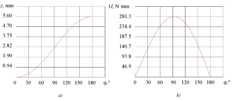
Fig. 4. Dependences of the studied values on the angle of rotation:
a — linear displacement of the output link;
b — torque M at the input link
From the presented graphical dependences, it could be established that the maximum displacement amount was achieved at a rotation angle approaching 180° and is 5.6 mm, and the torque data peaked at 281.3 N•mm at rotation angle φ = 93°.
As a result of simulation modeling, a displacement schedule of output link L004 was obtained depending on the rotation of the actuator link L001 (Fig. 5). The movement of the elementary segment of the lever mechanism occurred until the right and left levers touched in the extreme position. Since the levers had volume, a complete rotation of the output link was impossible due to the side surface contact, which is also shown on the graph (Fig. 5). To achieve a complete rotation, it is required to change the structure of the lever to a more complex shape. Figure 6 shows the dependence of the torque when turning the chain segment of the calculated model by 180°.
![]()
Fig. 5. Travel schedule of the output link in the relative coordinate system
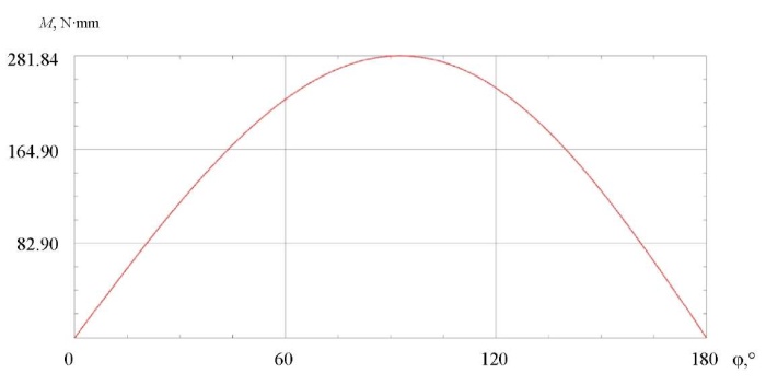
Fig. 6. Graph of torque change during the simulation experiment
The values of the studied parameters obtained through simulation (simulation experiment) differed from the values obtained theoretically by no more than 3 %.
Discussion and Conclusions. Within the framework of the presented work, kinematic and power analyses of the elementary segment of the actuator chain of the manipulator were carried out. The obtained analytical dependences made it possible to determine the maximum amount of linear displacement and the developed torque in the actuator segment. The results of the simulation experiment implemented in NX Nastran environment and the subsequent comparative analysis showed a good correspondence of the obtained analytical dependences with respect to the three-dimensional dynamic model of the object. This allowed us to conclude that the obtained analytical dependences could be used in the development of a control system for the actuators of the above-mentioned manipulator devices. The conducted studies showed that the chain of segments of the lever mechanism in question had good transmission properties and, with sufficient length, could replace the transmission based on twisting the string. However, the device of the studied transmission is more complex. Despite this, the transmission based on twisting a chain of segments has the advantage of being able to provide a greater number of operating cycles of the manipulator device while maintaining the required positioning accuracy and repeatability due to less deformations of the chain elements.
1. Gaponov II, Nedelchev SI. Mechatronic drive on twisted threads. RF Patent no. 2020144036, IPC F 16 H 35/00; 2021 (In Russ.)
1. Гапоненко, Е. В. Структурный анализ и классификация роботизированных систем с приводными механизмами на основе кабельных элементов / Е. В. Гапоненко, Л. А. Рыбак, Л. Р. Холошевская // Вестник БГТУ им. В. Г. Шухова. — 2019. — Вып. 9. — С. 126–136.
2. Gaponov, I. Twisted String Actuation Systems: A Study of the Mathematical Model and a Comparison of Twisted Strings / I. Gaponov, D. Popov, Jee-Hwan Ryu // IEEE/ASME Transactions on Mechatronics. — 2014. — Vol. 19. — P. 1331–1342. https://doi.org/10.1109/TMECH.2013.2280964
3. A wearable robotic device based on twisted string actuation for rehabilitation and assistive applications / M. Hosseini, R. Meattini, G. Palli, C. Melchiorri // Journal of Robotics. — 2017. — Vol. 2017. — Art. 3036468. http://dx.doi.org/10.1155/2017/3036468
4. Sonoda, T. Multi-fingered robotic hand employing strings transmission named “Twist Drive” / T. Sonoda, I. Godler // In: Proc. IEEE/RSJ Int. Conf. on Intelligent Robots and Systems. — 2010. — P. 2733–2738. http://dx.doi.org/10.1109/IROS.2010.5652886
5. The Twisted String Actuation System: Modeling and Control / T. Wuertz, Ch. May, B. Holz [et al.] // IEEE/ASME Transactions on Mechatronics. — 2010. — Vol. 18. — P. 1215–1220. http://dx.doi.org/10.1109/AIM.2010.5695720
6. Integrated mechatronic design for a new generation of robotic hands / G. Berselli, G. Borghesan, M. Brandi [et al.] // IFAC proceedings Volumes. — 2009. — Vol. 42. — P. 8–13. https://doi.org/10.3182/20090909-4-JP-2010.00004
7. The DEXMART hand: Mechatronic design and experimental evaluation of synergy-based control for human-like grasping / G. Palli, C. Melchiorri, G. Vassura [et al.] // The International Journal of Robotics Research. — 2014. — Vol. 33. — P. 799–824. http://dx.doi.org/10.1177/0278364913519897
8. The modular multisensory DLR-HIT-Hand: Hardware and software architecture / Honh Liu, Peter Meusel, Gerd Hirzinger [et al.] // IEEE/ASME Transactions on Mechatronics. — 2008. — Vol. 13. — P. 461–469. https://doi.org/10.1109/TMECH.2008.2000826
9. Лапшин, В. В. О принципе виртуальных перемещений / В. В. Лапшин // Вестник МГТУ им. Н. Э. Баумана. — 2012. — № 2(45). — С. 59–64.
10. Воробьева, Н. С. Разработка базы моделей манипулятора параллельно-последовательной структуры / Н. С. Воробьева, В. В. Дяшкин-Титов, А. В. Дяшкин // Известия ЮФУ. Технические науки. — 2017. — № 9(194). — С. 143–152.
11. Михайленко, Н. И. Применение принципа возможных перемещений к решению технических задач / Н. И. Михайленко, Э. Я. Живаго // Вестник СибГИУ. — 2013. — № 1(3). — С. 58–63.
12. Вдовин, Д. С Виртуальный стенд для определения нагрузок на рулевое управление автомобиля / Д. С. Вдовин, И. В. Чичекин, Т. Д. Поздняков // Инженерный журнал: наука и инновации. — 2017. — № 8(68). — С. 1–12.
13. Čepon, G. Introduction of damping into the flexible multibody belt-drive model: A numerical and experimental investigation / G. Čepon, L. Manin, M. Boltežar // Journal of Sound and Vibration. — 2009. — Vol. 324. — P. 283–296. https://doi.org/10.1016/j.jsv.2009.02.001
14. Malaka, J. Generating numerical multibody model of toothed belt in technological machines with Siemens NX. / J. Malaka, M. Hetmańczyk // International Journal of Modern Manufacturing Technologies. Special Issue. — 2021. — Vol. XIII. — P. 87–95. http://dx.doi.org/10.54684/ijmmt.2021.13.3.87
15. Нужный, А. М. Параметризация твердотельных моделей с использованием NX OPEN / А. М. Нужный, М. В. Веркошанский, Н. И. Гребенникова, С. Л. Кенин // Вестник ВГТУ. — 2019. — Т. 15, № 3. — С. 24–27.
46, Kostyukova St., Belgorod
46, Kostyukova St., Belgorod
46, Kostyukova St., Belgorod
46, Kostyukova St., Belgorod
Bondarenko I.R., Voloshkin A.A., Perevuznik V.S., Kovalev L.A. Calculation of the force and kinematic parameters of the transfer mechanism based on a twisted arm chain. Advanced Engineering Research (Rostov-on-Don). 2022;22(2):91-98. https://doi.org/10.23947/2687-1653-2022-22-2-91-98


Advanced Engineering Research (Rostov-on-Don)
ISSN 2687-1653 (Online)
Contact with: Publisher / Editorial Office of the Journal
Publisher: Don State Technical University - DSTU, Rostov-on-Don, Russia - https://donstu.ru/en/
Editor-in-Chief: Alexey N. Beskopylny, Dr.Sci. (Eng.), Professor, Vice-Rector, Don State Technical University (Rostov-on-Don, Russia)
Don State Technical University
1, Gagarin Sq., Rostov-on-Don, 344003, Russia
tel.: +7 (863) 2738-372, e-mail: vestnik@donstu.ru
16+
Processing of personal data


