


Contents
Scroll to:
https://doi.org/10.23947/2687-1653-2022-22-2-116-129
Scroll to:
Introduction. Domestic and foreign works on the milling of complex-profile surfaces with a ball-end tool were analyzed. Methods of surface quality control and ways to provide amplitude parameters of roughness, based on research data and field experiments, were considered. Theoretical provisions on the determination of cutting forces and the results of vibroacoustic diagnostics were presented.
Materials and Methods. The methods of correlation analysis, comparison and generalization of the results were applied. The data were calculated at different tool angles, taking into account the instantaneous cutting forces, and were fixed in the range of values of the variable feed per tooth (fz) and the angle of inclination of the surface (γ). The vibroacoustic diagnostic data and theoretical data of the presented model at different tool inclination angles were verified by experiment. Consequently, such methods can be used to predict surface roughness parameters.
Results. The relationship between cutting forces, tool inclination angle, and vibroacoustic diagnostics data was found. A model of the cutting force and tool displacements was formulated taking into account the inclination of the surface. The optimal range of the inclination angle of the tool to the surface to be machined, at which the minimum values of the amplitude parameters of roughness were achieved, was determined. The sound vibrations obtained empirically, presented in spectral and wave forms, were in good agreement with data from other sources. This allowed us to conclude about the feasibility of forecasting and monitoring roughness parameters in real time through acoustics.
Discussion and Conclusions. It was established that the growth of forces in the direction ae(X) and fz(Y) was observed at γ > 40°. This was due to the distribution of the components of the cutting force along the cutting edge and depended on the inclination of the surface. The amplitude parameters decreased when the angle increased from 10 to 40 degrees. The found interrelations of force analysis, processing directions, and vibroacoustic diagnostics have validated the use of vibroacoustic diagnostics to predict surface roughness. Acoustic diagnostics, regardless of the layout of technological equipment, enables to quickly adjust the sound device and assess the impact of cutting modes on roughness parameters.
Gimadeev M.R., Li A.A. Analysis of automated surface roughness parameter support systems based on dynamic monitoring. Advanced Engineering Research (Rostov-on-Don). 2022;22(2):116-129. https://doi.org/10.23947/2687-1653-2022-22-2-116-129
Introduction. Specialists do not have enough software tools that could help predicting the value of the cutting force, vibration amplitude, etc., when programming machines with numerical control (CNC). As a result, it is required to select the feed rate based on experience, setting a constant feed rate for the entire processed complex surface. This can reduce the processing efficiency and surface quality. To solve this problem, it is required to build a highly accurate and reliable model for predicting surface roughness.
Currently, two main approaches are used in such forecasting. In the first case, photoelectric sensors transmit roughness data online. This method efficiency is quite low because chips are formed during the cutting process, and a lubricating fluid (lubricoolant) is supplied to the area of the recorded microrelief. The second group includes control methods using artificial intelligence, as well as theoretical modeling and modeling of empirical regression analysis. In practice, methods from the second group are most common.
The authors of paper [1] explored the spherical tool milling of aerospace components made of aluminum alloy LM6 and developed a model using ARMAX structures (autoregressive moving average with exogenous inputs) to predict surface roughness under various processing modes. In [2], a mathematical model of the trajectory of a spherocylindrical tool for processing mushroom-shaped blades of a steam turbine was presented to improve the processing efficiency and surface quality. The authors [3] created an analytical model of the milling with a spherocylindrical tool and considered the situation of vibration occurrence to predict the limits of tool stability at different angles of inclination and spindle rotation speed.
In [4], the processing of the impeller on a five-axis CNC machine using a spherical cylindrical tool was studied. The tool trajectory and optimal cutting modes had to be developed due to the complex curved surface and the close location of the wheel blades, since in this case, it was impossible to use standard CAM systems (computer-aided manufacturing - an automated system or its module for the preparation of control production programs).
In [5], a system for optimizing the feed rate for three-axis milling with a spherical tool was described. The authors used the geometric modeling capabilities of B-rep ACIS: miter cutting was converted to an orthogonal model for various tools and workpieces. The authors [6] created a mathematical model of a constant cutting force [7] for processing a complex curved surface with a spherocylindrical tool on a CNC machine through maintaining a constant cutting speed at different tool inclination angles. Paper [8] presents a dynamic model of the milling with a spherical cylindrical tool, including cutting modes and tool edge wear. The authors [9] developed a real-time monitoring system with error compensation to improve accuracy in the production of free-form parts. In [10], the energy consumption of various cutting strategies was studied to evaluate the efficiency of each cutting strategy. The authors of this work have established that the optimal strategy enables to provide the specified parameters of surface quality. Many scientists used the Taguchi method to optimize processing parameters [11–13]. Some of the surveys are narrowly focused, and more work is needed to scale up the results [14–18].
The analysis of literature sources found the absence of recommendations on using the method of forecasting and monitoring roughness in real time. This is even more so in cases where sound vibrations in the air are taken into account.
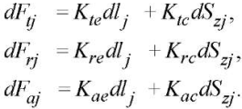
Materials and Methods. To determine the cutting forces, a model from [7][19] is used:
 (1)
(1)
Here, Kte, Kre, Kae — edge specific coefficients; Ktc, Krc, Kac — shear specific coefficients; dlj — incremental cutting-edge length lj [20]; Szj — cross-sectional area of the cut segment.
In this model, a set of curvilinear coordinate systems, perpendicular to the tangents to the spherical surface, is used to set the resulting force acting on the i-th infinitesimal segment of the cutting edge.
The geometry of the spherocylindrical end mill is schematically shown in Figure 1.
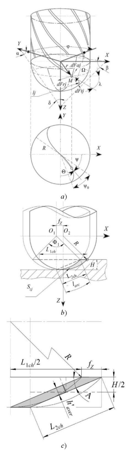
Fig. 1. Diagram for determining:
a — cutting forces of a spherocylindrical cutter;
b — segment to be cut;
c — cross-sectional area of the given figure [16]
The diagram shows the angle of inclination λ of a milling cutter with a spherocylindrical initial surface of the tool along the cutting edge. Here, we also see:
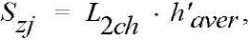 (2)
(2)
where L2ch — length of the second chord, mm; h’aver — average chip thickness, mm.
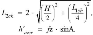 (3), (4)
Length of the first chord L1ch, arc length larc, and circle segment angle Ф1:
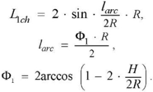 (5), (6), (7)
Angle А (Fig. 1 c) for calculating the average chip thickness:
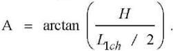 (8)
(8)
Radius vector r of the current point of the initial tool surface:
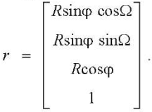 (9)
(9)
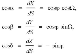
The equation of the cutting edge is solved as the equation of a curve located on the original instrumental surface and crossing the meridians at angle λ 90°. A parametric equation of the form Ω = Ω (φ) describes a certain line on the sphere. Cosines of the angles between the axes of XYZ coordinate system of the spherocylindrical cutter and the tangent line to the curve Ω = Ω (φ) on the initial tool surface:
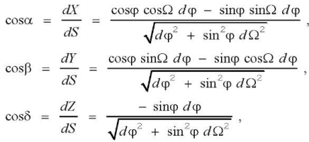 (10)
(10)
where dS — cutting edge arc differential.
Cosines of the angles between the coordinate axes and the tangent to the meridian (at Ω = const) on the initial tool surface are represented as Radzevich’s dependences [21]:
 (11)
(11)
We set the condition: Ω = λ. Then, the cutting-edge equations in parametric form:
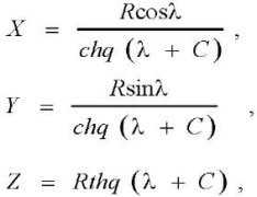 (12)
(12)
where ch — hyperbolic cosine, th — hyperbolic tangent.
To determine the infinitesimal length of the cutting edge, we can use the expression proposed in [7][16][19]:
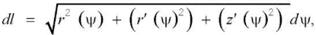 (13)
(13)
where
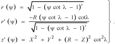 (14)
(14)
Main Text
Experiment Details. At the preparatory stage, the literature was studied [22–27]. The data for planning the experiment are described below. Machining was carried out in passing and counter directions (Fig. 2), on blanks with the properties of steel 45 (foreign analogues — C45, 1045). We used a spherocylindrical end carbide milling cutter with a diameter of D = 8 mm, with two teeth from Sandvik Coromant (z = 2). The ratio of the overhang of the tool installed in the chuck was taken as l / D, equal to 4. The milling tool made of fine-grained tungsten carbide had anti-wear coating TiAlN and parameter λ = 30°. Feed per tooth fz = 0.2 mm/tooth, allowance for all samples ap = H = 0,2 mm, lateral pitch ae = 0,2 mm.
To provide equal cutting speed Vc at different angles of inclination (γ) of the tool to the surface to be processed, the rotation frequency (n) varied in the range from 1478 min–1 to 8000 min–1.
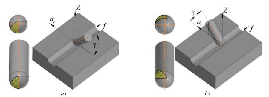
Fig. 2. Types of the conditional contact surface of workpiece
and tool at different values of tool inclination angles in the direction:
a — passing; b — counter
Angle γ was selected from the range from 10° to 50°; therefore, the calculation of the effective diameter Dcap (L1ch) was carried out using the formulas:
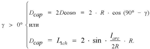 (15)
(15)
In the experiments, a DMG DMU 50 CNC machine (Heidenhain control system) was used. The surface roughness after treatment was measured using profilometer-profilograph-contorograph Surfcam 1800D. In accordance with the current standards1, measurements were carried out along various routes. To find the maximum values of the surface roughness parameters, 50 % Gaussian filtration was used. Vibroacoustic diagnostics was performed according to GOST R ISO 7919-3-992 using spectrum analyzer Zet 017-U2. As an output evaluation of the processing efficiency, amplitude А of the vibrations of the spindle assembly (mm), varying with time (t, s) was used.
Research Results. The experiment has shown that the real surface roughness differs significantly from the data of theoretical models — the results of the kinematic-geometric projection of the tool on the workpiece. Currently, there is a growing demand for details of a spatially complex configuration and surface quality requirements. In this regard, it is worth focusing on the requirements of predictability of machining results, expressed, among other things, by roughness indicators.
Tables 1 and 2 present the results of the experiment of amplitude parameters of roughness described in GOST R ISO 42883.
Table 1
Roughness parameters depending on the machining direction with a spherocylindrical tool under climb milling
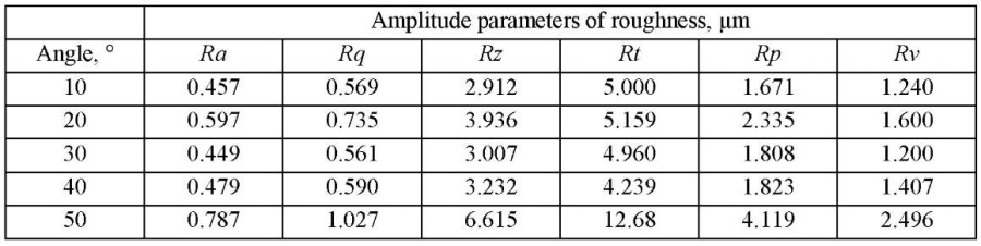
Table 2
Roughness parameters depending on the machining direction with a spherocylindrical tool under up-cut milling
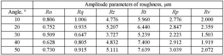
Analyzing the data of Tables 1 and 2, we note that the prevailing influence on the “height” of the roughness is exerted by the cutting direction. The quantitative value of the amplitude parameters is “lower” under climb milling. Hereafter, we will talk only about this type of milling. Based on the data in Table 1, a correlation analysis was performed, and a correlogram was made up (Fig. 3). The found dependences were correlated with the results of papers [28][29].
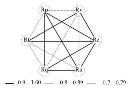
Fig. 3. Correlogram of the amplitude roughness parameters after milling under climb milling
The equations obtained during the correlation analysis helped us to move away from the direct normalization of roughness parameters. At the same time, analytical dependences provided minimizing the number of controlled factors. This reduced the complexity of the transition to real-time monitoring of sound vibrations.
In the presented study, the cutting forces (Fx, Fy, Fz) were calculated (Fig. 4). It can be seen that the inclination angle of the surface γ affected significantly the cutting forces.
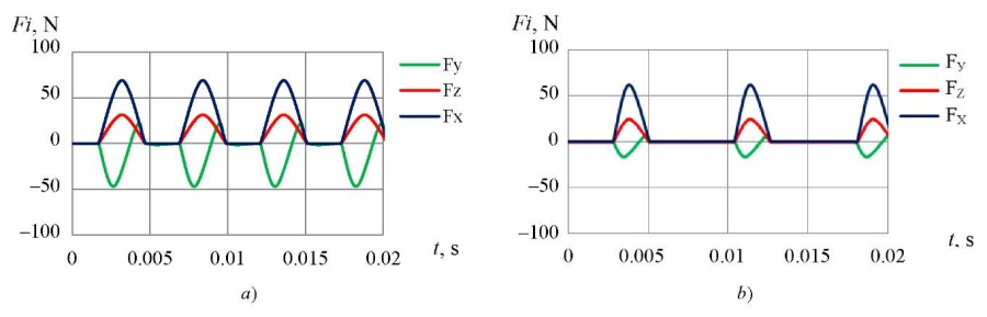
Fig. 4. Cutting forces calculated for: a — γ = 10; b — γ = 40
The data obtained allowed us to establish that the forces decreased with an increase in the tool inclination angle from 10° to 40°. In addition, force Fx was most sensitive when the inclination angle of the surface changed. It should also be noted that the cutting forces calculated according to the above-mentioned method were in good agreement with the empirical results obtained [6][17][24][26][27][30].
With an increase in angle γ, the maximum area of plunging of the tool into the workpiece decreased (determined by the working angle and the active number of teeth zc). Consequently, when finishing milling with a spherocylindrical tool, “pulsating” forces may be present, since for the inclination angle of the surface γ > 0°, the number of active teeth is often less than one (zc < 1).
To establish zc, sound vibrations during cutting were analyzed. The authors of [31] proposed to divide the spectrum of vibrations of working bodies into ranges:
The experimentally obtained range of sound vibrations is shown in Figure 5.
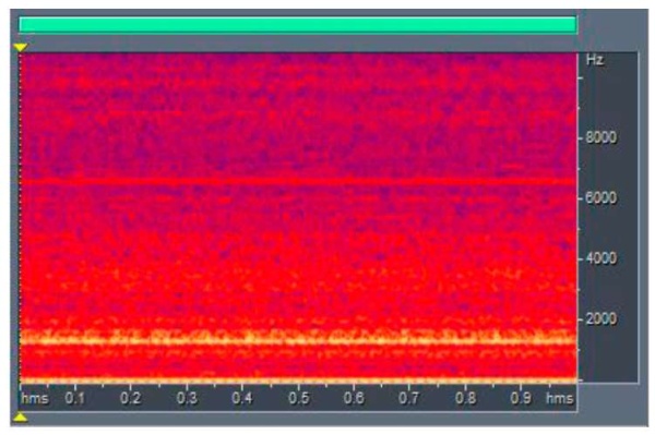
Fig. 5. Experimentally obtained spectral type of sound wave (segment is 1 sec)
The vibrations of the mounting elements and feed drives should be attributed to the low frequency range, the frequency of tool, spindle, etc. — to the medium and high frequency ranges. In this work, from the point of view of acoustic diagnostics, optimal cutting modes were determined that supported the stable operation of the technological system.
The frequency corresponding to the cutting frequency was pre-determined (Fig. 6). Filtering was applied to sound vibrations under:
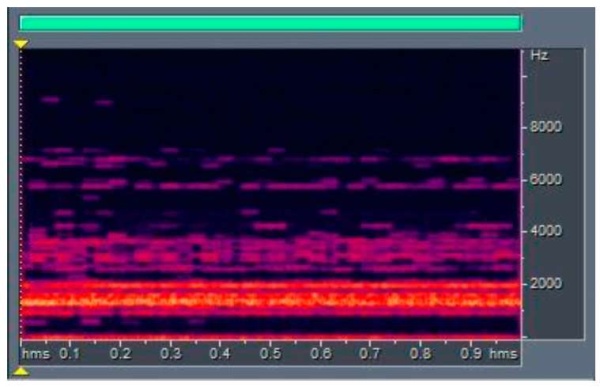
Fig. 6. Spectrogram of the sound wave after filtering (segment is equal to 1 sec)
Some spread in values (Fig. 6), associated with a huge number of factors that were difficult to exclude when conducting a full-scale experiment, is noteworthy.
The middle of the pronounced frequency range shown in Figure 5 corresponded to a rotation of 1500 rpm with a tool tilt of 40°. Acoustic diagnostics confirmed that the cutting went on almost continuously, i.e., without shock “pulsating” loads. The latter situation is shown in Figure 7. Here, the allocated evaluation time is 0.5 s, the number of periods is 25.
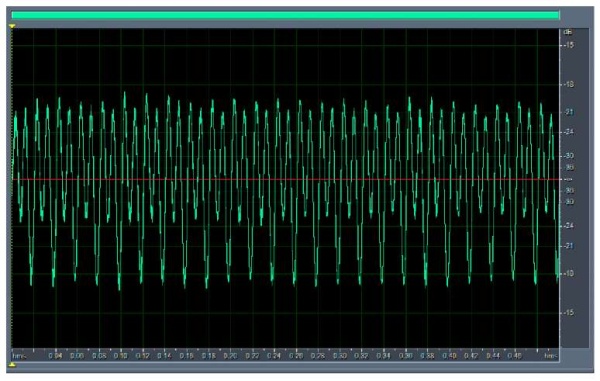
Fig. 7. Filtered fragment of the sound wave based on the sound of cutting at γ = 40° (segment is 1/2 sec)
Figure 7 shows an ambiguously interpreted sound wave. However, it is quite easy to characterize it if we delve into the essence of mechanical milling. Under the climb milling and rounding of the cutting edge, plastic deformations of the metal with residual stresses remain on the treated surface. Even with proper coolant supply, temperature deformations occur in the surface layers of the material and distort the crystal lattice (residual stresses of the III kind). Along with this, after removing the tool, the stretched upper layers of the metal acquire residual compression stresses. If we describe the machining from the kinematics of the process, of note, the chip removal factor, namely value ϴ2 — the cutting angle of the material with the inclined spindle in the passing direction (Fig. 8).
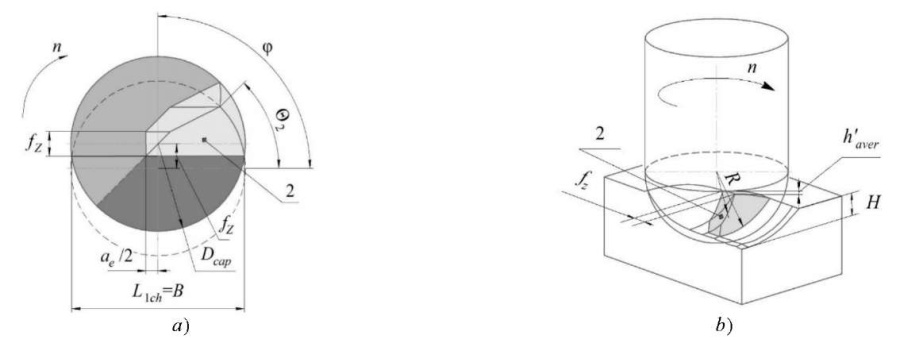
Fig. 8. Segment 2 to be cut off during machining:
a — top view; b — projection of the segment being cut [16]
We specify that the tool cut in zone 2. The data obtained were validated by the simulation results, but were considered for the ideal case.
Along with these factors, theoretical and empirical discrepancies were often caused by vibrations associated with tool deflection and wear, as well as with the geometry of the cutting zone. Figure 7 shows the process of cutting the workpiece material with the j-tooth of the tool, which, along with other factors, determines such an interesting shape of the resulting wave.
In addition to the above, Figure 9 presents dependences which show that with a decrease in the amplitude of vibrations, the angle of inclination increased from 10° to 40°.
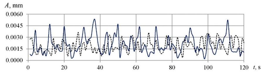
Fig. 9. Vibration amplitudes depending on the surface inclination angle:
solid line — 10°, dotted line — 40°
M. R. Gimadeev and V. V. Gusliakov4 analyzed the international practice of profile assessment of surface roughness. The authors of work [32] put forward proposals for the transition to a three-dimensional assessment. In the presented study, roughness measurements were carried out in an orthogonal coordinate system to make a comprehensive assessment.
The analysis of the profilograms obtained (Fig. 10) allowed us to conclude about the regularity of the surface microrelief after processing with a spherocylindrical end mill. In this case, it is impractical to take into account the roughness of the tool, since its manifestations are insignificant. Some additional increase in roughness was observed in the direction of the side pitch ae, which verified the increase in elastic squeezes of the tool. The presented profiles, where the profile periods (peak-to-valley) correspond to a given feed value fz = 0.2 mm/tooth, testify to this.
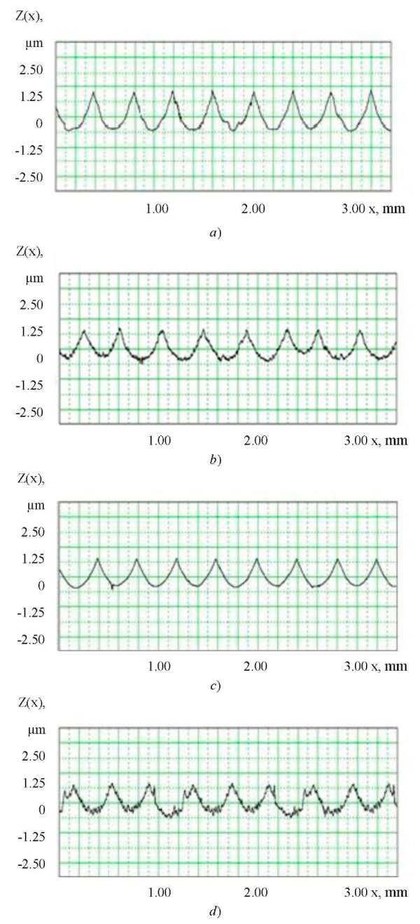
Fig. 10. Profilograms of surfaces after milling at different inclination angles γ:
a — γ = 10; direction fz;
b — γ = 10; direction ae;
c — γ = 40; direction fz;
d — γ = 40; direction ae
Photomicrographic images of the treated surface have an obvious hexagonal shape (Fig. 11). The quality of the machined surface in the direction of the side pitch ae may decrease due to the cutting tool retraction and an increase in the amplitude of the technological system vibrations under milling. This is validated by the results of vibroacoustic diagnostics.
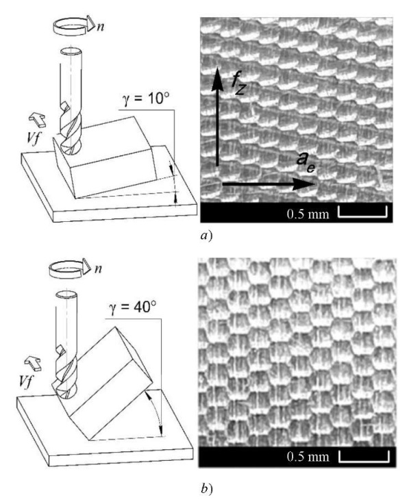
Fig. 11. Milling scheme and photo of the treated surface at: a — γ = 10; b — γ = 40
We emphasize once again that the experimental results correlate with the data obtained by many authors, and are consistent with the theories of elasticity, shaping, material cutting, and mechanical engineering technology.
Discussion and Conclusions. The influence of the inclination angle of the treated surface on the cutting forces, vibrations and microrelief parameters was studied. A model of cutting force and vibration was created, including kinematic and geometric parameters. The study has shown that quantitatively and qualitatively the cutting forces and vibrations of the cutting tool depend on the angle of inclination of the surface.
An analysis of the experimental data made it possible to identify a trend towards a decrease in the amplitude parameters of roughness by 10–20 % with an increase in the angle of inclination to 30–40°. The quality of the treated surface was reduced due to the elastic retraction of the spherocylindrical tool and an increase in the amplitude of vibrations of the technological system.
It was established that the forces grew in direction ae(X) and fz(Y) at γ > 40°. This can be explained by the distribution of the cutting force components along the cutting edge, which depends on the inclination of the surface.
The solutions to the problems of monitoring and analysis of roughness parameters obtained by the authors due to acoustic diagnostics can significantly reduce the volume of experimental studies. This approach makes it possible to significantly reduce the cost of material resources and time for mechanical processing of products.
The experimental results are of practical interest and make the information about the formation of microrelief, including the roughness parameters under mechanical cutting, more accurate. A more detailed study of the proposed method of acoustic diagnostics is needed.
1. GOST 27964-88. Measurement of surface roughness parameters. Terms and definitions. Moscow, 2018. 13 p. (In Russ.)
2. GOST R ISO 7919-3-99. Mechanical vibration of non-reciprocating machines. Measurements on rotating shafts and evaluation criteria. Moscow, 2000. 12 p. (In Russ.)
3. GOST R ISO 4287-2014. Geometrical Product Specifications (GPS). Surface texture. Profile method. Terms, definitions and surface texture parameters. Moscow, 2015. 20 p. (In Russ.)
4. Gimadeev MR. Analiz zarubezhnogo opyta pri frezerovanii sferotsilindricheskim instrumentom. Khabarovsk: Informatsionnye tekhnologii XXI veka; 2019. P. 330–334. (In Russ.)
1. Vijiakumar. S. Jatti. Machine learning based predictive modeling of ball nose end milling using exogeneous autoregressive moving average approach / Vijiakumar S. Jatti, Ravi Sekhar, Pritesh Shah // In: Proc. 2021 12th IEEE Int. Conf. on Mechanical and Intelligent Manufacturing Technologies (ICMIMT). — 2021. — P. 68–72. https://doi.org/10.1109/ICMIMT52186.2021.9476067
2. Zhou Lingli. Research and development of fungus shaped blade root CAM software based on VB / Zhou Lingli, Liu Guoqing, Xiong Xiaocong // In: Proc. 2021 4th IEEE Int. Conf. on Pattern Recognition and Artificial Intelligence (PRAI). — 2021. — P. 291–295. https://doi.org/10.1109/PRAI53619.2021.9551076
3. Koichi Akazawa. Study on regenerative chatter vibration in ball end milling of flexible workpieces / Koichi Akazawa, Eiji Shamoto // In: Proc. 2008 IEEE Int. Symposium on Micro-Nano Mechatronics and Human Science. — 2008. — P. 1–6. https://doi.org/10.1109/MHS.2008.4752412
4. Xiurong Zhu. Process analysis and parameter optimization of five axis NC machine for machining complex curved surface impellers / Xiurong Zhu, Yeu Wang // In: Proc. 2019 IEEE Int. Conf. on Intelligent Transportation, Big Data & Smart City (ICITBS). — 2019. — P. 122–124. https://doi.org/10.1109/ICITBS.2019.00036
5. Salami, R. Feed rate optimization for 3-axis ball-end milling of sculptured surfaces / R. Salami, M. H. Sadeghi, B. Motakef // International Journal of Machine Tools & Manufacture. — 2007. — Vol. 47. — P. 760–767. https://doi.org/10.1016/j.ijmachtools.2006.09.011
6. The simulation of cutting force of free-form surface machining with ball-end milling cutter / Lei Shi, En Fu Liu, Yi Zhang [et al.] // In: Proc. 2009 IEEE Int. Conf. on Industrial Engineering and Engineering Management. — 2009. — P. 2314–2318. https://doi.org/10.1109/IEEM.2009.5373028
7. Altintas, Y. Mechanics and dynamics of ball end milling / Y. Altintas, P. Lee // Journal of Manufacturing Science and Engineering. — 1998. — Vol. 120. — P. 684–692. https://doi.org/10.1115/1.2830207
8. Influence of vibration amplitude on tool wear during ball end milling of hardened steel / A. V. Anstev, Ngon Dang Thien, Trong Dang Huu, E. S. Yanov // In: Proc. 2018 4th IEEE Int. Conf. on Green Technology and Sustainable Development (GTSD). — 2018. — P. 232–236. https://doi.org/10.1109/GTSD.2018.8595567
9. Spatial statistical analysis and compensation of machining errors for complex surfaces / Yueping Chen, Jian Gao, Haixiang Deng [et al.] // Precision Engineering. — 2013. — Vol. 37. — P. 203–212. https://doi.org/10.1016/j.precisioneng.2012.08.003
10. Vila, C. Study of different cutting strategies for sustainable machining of hardened steels / C. Vila, J. V. Abellán-Nebot, H. R. Siller-Carrillo // Procedia Engineering. — 2015. — Vol. 132. — P. 1120–1127. https://doi.org/10.1016/j.proeng.2015.12.604
11. Thakre, A. A. Optimization of milling parameters for minimizing surface roughness using Taguchi’s Approach / Avinash A. Thakre // International Journal of Emerging Technology and Advanced Engineering. — 2013. — Vol. 3. — P. 226–230.
12. Amal, T. S. Machining parameters optimization in end milling of Ti6Al4V using Taguchi method / T. S. Amal, V. Vidya, A. K. Abraham // International Journal of Research in Engineering and Technology. — 2015. — Vol. 3. — P. 31–40.
13. Optimization of milling parameters of EN8 using Taguchi methodology / R. Ashok Raj, T. Parun, K. Sivaraj, T. T. M. Kannan // International Journal of Mechanical Engineering and Robotics Research. — 2013. — Vol. 2. — P. 202–208.
14. Study of the milling strategy on the tool life and the surface quality for knee prostheses / M. Boujelbene, P. Abellard, E. Bayraktar, S. Torbaty // Journal of Achievements in Materials and Manufacturing Engineering. — 2008. — Vol. 31. — P. 610–615.
15. Choubey, A. Optimization of process parameters of CNC milling machine for mild steel using Taguchi design and Single to Noise ratio Analysis / А. Choubey, V. Chaturvedi, J. Vimal // International Journal of Engineering Research and Technology. — 2012. — Vol. 1. — P. 1–12.
16. Gimadeev, M. R. Cutting Forces and Roughness During Ball End Milling of Inclined Surfaces / M. R. Gimadeev, V. A. Stelmakov, V. V. Gusliakov // In: Proc. the 6th International Conference on Industrial Engineering — 2021. — Vol. II. — P. 926–937. https://doi.org/10.1007/978-3-030-54817-9_107
17. Predictive force model for ball-end milling and experimental validation with a wavelike form machining test / M. Fontaine, A. Devillez, A. Moufki, D. Dudzinski // International Journal of Machine Tools & Manufacture. — 2006. — Vol. 46. — P. 367–380. https://doi.org/10.1016/j.ijmachtools.2005.05.011
18. Cutting force estimation in sculptured surface milling / A. Lamikiz, L. N. López de Lacalle, J. A. Sánchez, M. A. Salgado // International Journal of Machine Tools & Manufacture. — 2004. — Vol. 44. — P. 1511–1526. https://doi.org/10.1016/j.ijmachtools.2004.05.004
19. Altintaş, Y. A general mechanics and dynamics model for helical end mills / Y. Altintaş, P. Lee // CIRP Annals. — 1996. — Vol. 45. — P. 59–64. https://doi.org/10.1016/S0007-8506(07)63017-0
20. Bouzakis, K. D. Determination of the chip geometry, cutting force and roughness in free form surfaces finishing milling, with ball end tools / K. D. Bouzakis, P. Aichouh, K. Efstathiou / International Journal of Machine Tools & Manufacture. — 2003. — Vol. 43. — P. 499–514. https://doi.org/10.1016/S0890-6955(02)00265-1
21. Радзевич, С. П. Формообразование поверхностей деталей. Основы теории / С. П. Ралзевич. — Киев : Растан, 2001. — 592 с.
22. Гимадеев, М. Р. Обеспечение качества поверхности при механообработке сложнопрофильных деталей / М. Р. Гимадеев, В. М. Давыдов // Технология машиностроения. — 2018. — № 11. — С. 9–16.
23. Toh, C. K. A study of the effects of cutter path strategies and orientations in milling / C. K. Toh // Journal of Materials Processing Technology. — 2004. — Vol. 152. — P. 346–356. https://doi.org/10.1016/j.jmatprotec.2004.04.382
24. Cutting force prediction for ball nose milling of inclined surface / K. V. R. Subrahmanyam, Wong Yoke San, Geok-Soon Hong, Huang Sheng // The International Journal of Advanced Manufacturing Technology. — 2010. — Vol. 48. — P. 23–32. https://doi.org/10.1007/s00170-009-2275-5
25. Modeling of cutter displacements during ball end milling of inclined surfaces / S. Wojciechowski, T. Chwalczuk, P. Twardowski, G. M. Krolczyk // Archives of Civil and Mechanical Engineering. — 2015. — Vol. 15. — P. 798–805. https://doi.org/10.1016/j.acme.2015.06.008
26. Пономарев, Б. Б. Влияние ориентации инструмента на силы резания при концевом фрезеровании / Б. Б. Пономарев, Ши Хьен Нгуен // Известия высших учебных заведений. Машиностроение. — 2019. — № 3 (708). — С. 11–20. https://doi.org/10.18698/0536-1044-2019-3-11-20
27. Пономарев, Б. Б. Моделирование и анализ влияния условий обработки на силы резания при концевом фрезеровании / Б. Б. Пономарев, Ш. Х. Нгуен // Современные технологии. Системный анализ. Моделирование. — 2018. — Т. 59, № 3. — С. 8–16. https://doi.org/10.26731/1813-9108.2018.3(59).8-16
28. Гимадеев, М. Р. Корреляционные связи показателей шероховатости при фрезеровании сферическим инструментом / М. Р. Гимадеев, В. М. Давыдов // Тяжелое машиностроение. — 2018. — № 9. — С. 24–29.
29. Формирование параметров шероховатости на основе корреляционных связей при чистовом фрезеровании пространственно-сложных поверхностей / В. М. Давыдов, М. Р. Гимадеев, А. В. Никитенко, А. В. Сарыгин // Упрочняющие технологии и покрытия. — 2019. — Т. 15, № 6 (174). — С. 243–248.
30. Пономарев, Б. Б. Выбор оптимальных параметров стратегии фрезерования поверхностей сложной формы / Б. Б. Пономарев, Д. Б. Пайкин // Вестник ИрГТУ. — 2010. — № 6 (46). — С. 52–56.
31. Аршанский, М. М. Вибродиагностика и управление точностью обработки на металлорежущих станках / М. М. Аршанский, В. П. Щербаков. — Москва : Машиностроение, 1983. — 136 с.
32. Анализ международной практики профильной и трехмерной оценки шероховатости поверхности / В. М. Давыдов, В. В. Заев, П. Н. Паночевный [и др.] // Ученые заметки ТОГУ. — 2013. — Т. 4, № 4. — С. 1061–1074.
136, Tihookeanskaya St., Khabarovsk
136, Tihookeanskaya St., Khabarovsk
Gimadeev M.R., Li A.A. Analysis of automated surface roughness parameter support systems based on dynamic monitoring. Advanced Engineering Research (Rostov-on-Don). 2022;22(2):116-129. https://doi.org/10.23947/2687-1653-2022-22-2-116-129

Advanced Engineering Research (Rostov-on-Don)
ISSN 2687-1653 (Online)
Contact with: Publisher / Editorial Office of the Journal
Publisher: Don State Technical University - DSTU, Rostov-on-Don, Russia - https://donstu.ru/en/
Editor-in-Chief: Alexey N. Beskopylny, Dr.Sci. (Eng.), Professor, Vice-Rector, Don State Technical University (Rostov-on-Don, Russia)
Don State Technical University
1, Gagarin Sq., Rostov-on-Don, 344003, Russia
tel.: +7 (863) 2738-372, e-mail: vestnik@donstu.ru
16+
Processing of personal data


