


Contents
Scroll to:
https://doi.org/10.23947/2687-1653-2022-22-2-130-141
Scroll to:
Introduction. Some of the major factors in the occurrence of vibration of units, causing fatigue failure of the housings of elements, pipelines, and failure of pump elements, are pulsations of the working medium in the hydraulic systems of machine tools, fuel feed systems of aircraft engines and liquid-propellant engine supply. This study aimed at the implementation of a method for determining the dynamic characteristics of a volumetric pump using special bench systems, and the comparison of the calculation results to the experimental data. The stages of calculating the dynamic characteristics of a volumetric pump were described, taking into account the pre-developed special bench systems on the example of an external gear pump with a capacity of 14 cm3 /rev. The implementation of V. P. Shorin's load variation method using special bench systems developed by the authors with predetermined dynamic characteristics was shown. The main stages of the methodology for determining the dynamic characteristics of a gear pump were described.
Materials and Methods. Methods of spectral analysis of pulsating pressure were applied in the work. Pulsations of fluid flow at the pump outlet were determined using the impedance method, the method of load variation, and special bench systems.
Results. The paper implemented a technique for determining the dynamic characteristics of a gear pump in the drive shaft speed range of 500-2500 rpm for four harmonic components of the vibration spectrum in a wide range of dynamic loads (from inertial to capacitive nature). The bench systems yielding the calculation of the dynamic characteristics of the pump with a minimum error based on the condition of matching the dynamic load and the source of vibrations were analyzed. The developed approach to the evaluation of the dynamic characteristics of the pump was verified through comparing the calculated and experimental data of pressure pulsations in the bench systems with choke, cavity and an extended pipeline at the pump outlet.
Discussion and Conclusions. The method for determining the dynamic characteristics of a volumetric pump was implemented using special bench systems developed by the authors. The research results show that the gear pump under study can be considered as an independent source of flow fluctuations, for which the deviation of its own dynamic characteristics from the average values does not exceed 10% for the first harmonic component.
Sanchugov V.I., Rekadze P.D. Determination of the dynamic characteristics of a gear pump by the load variation method using special bench systems. Advanced Engineering Research (Rostov-on-Don). 2022;22(2):130-141. https://doi.org/10.23947/2687-1653-2022-22-2-130-141
Introduction. The main disadvantages of pumps are the acoustic noise that accompanies their operation, the vibration of the body, connected pipelines, and the resulting structural damage.
The traditional way of improving pump designs, used in mechanical engineering and consisting in smoothing out the uneven flow of the liquid, is hampered by the lack of means of direct measurement of fluid flow at the pump outlet. This limits any experimental evaluation of the design efficiency and finishing work on pumps. In addition, this limits the analytical description of the pump as a source of vibrations required by hydraulic system developers to provide the target dynamic quality of the systems by themselves.
For this reason, the research on the modeling of dynamic processes in hydromechanical systems [1][2] and the application of new approaches to solving problems of hydraulic system dynamics [3][4] based on physical principles are pressing issues.
Materials and Methods. The implementation of V. P. Shorin's method of load variation [4] is presented. It consists in determining pressure pulsations behind a pump interacting with several bench systems, whose dynamic characteristics are calculated in advance. Further, the processed frequency-response functions of the pressure using the impedance of the bench systems are recalculated into the pump's own dynamic characteristics — pulsation performance and impedance. The development of the approach provides that special bench systems are proposed. They take into account the connecting fittings, adapters and internal channels of the pump, which makes it possible to more accurately determine the dynamic characteristics of pumps, as well as to verify the applicability of the pump model used in the form of an equivalent source of vibrations.
Research Results
Method for determining the dynamic characteristics of a gear pump
Samara University has developed a computational and experimental method for determining the dynamic characteristics of a gear pump (pulsation performance and impedance), which is based on the research of L. Thevenin, E. Norton and V. P. Shorin [5][6]. The developed methodology includes the following main stages: creation of models and calculation of dynamic characteristics of special bench systems; experimental determination of pressure pulsations at the pump outlet; calculation of the spectrum of excited vibrations in various bench systems; determination of approximating dependences for individual harmonic components; calculation of the pump own dynamic characteristics (pulsation performance and impedance); evaluation of the independence (stability) of the dynamic characteristics of the pump from the characteristics of bench systems; verification of the applicability of the pump model used as an equivalent source of flow (or pressure) fluctuations. The following is an example of the implementation of the proposed technique using an external gear pump with a specific capacity of 14 cm3/rev.
Models and calculation of dynamic characteristics of special bench systems
Basic options of bench systems at the liquid outflow during pump tests were considered. In concentrated parameters, the bench system can implement active flow-dependent, inertial, and elastic loads. In distributed parameters, the bench system can be provided in the form of an extended cylindrical pipeline implementing an active frequency-independent non-reflective load.
Pump models in the form of equivalent source of flow fluctuations (ESFF) or pressure (ESPF) are determined using constant flow source Q0, an ideal source of pressure fluctuations p (or flow q) and internal impedance Zи [4]. Figure 1 shows pump models in the form of an equivalent source of pressure fluctuations (and flow) with an attached system.
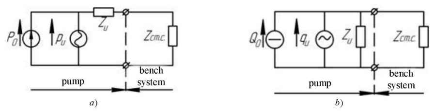
Fig. 1. Pump models in the form of an equivalent source of:
а — pressure fluctuations;
b — flow with attached system Q0 , P0 — average flow and pressure;
pИ, qИ — pump's own pulsating performance in terms of pressure and flow,
Zи, Zст.с — impedance of pump and bench system (adapted from [4])
In this connection, the task of selecting a bench system is to provide such system parameters at which the best conditions for high measurement accuracy are realized. The task of selecting the parameters of the attached system should be carried out when the impedance changes in the range from -∞ to +∞.
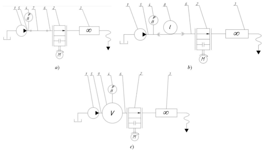
Fig. 2. Schematic diagrams of the bench systems for determining own dynamic characteristics of pumps:
a — with active throttle load;
b — with active non-reflective load;
c — with capacitive load:
1 — test pump; 2 — load choke; 3 — flow meter;
4 — pressure sensor; 5, 6 — connecting fittings;
7 — main line; 8 — extended pipeline; 9 — cavity
Computational models of impedances of special bench systems:
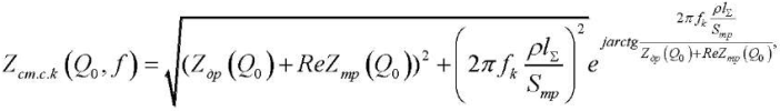 (1)
(1)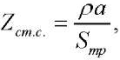 (2)
(2) (3)
(3)The formulas indicate: Zдр(Q0) — impedance of the throttle; ReZтр(Q0) — real part of the impedance of the pipeline, including the connecting line, fittings, internal channels in the pump and throttle; ReZлам(Q0), ReZтурб(Q0), ReZм.с.(Q0) — real part of the impedance of the fittings and the internal channel in the pump and cavity with laminar, turbulent fluid flow behind the pump and local resistances, respectively; fk — frequency k-th of the harmonic component of the vibration spectrum behind the pump; ρ — density of the working environment; lΣ — pipeline length, including the length of main line 6, connecting fittings 5 and 7 and internal channels of the pump and throttle (not shown in Fig. 7); Sтр — cross-sectional area of the pipeline; L — “inertia” of the connecting fittings and the internal channel in the pump and cavity; С — elasticity of the cavity; k — number of the harmonic component of the vibration spectrum; j — imaginary unit 
Using a bench system with a throttle at the pump outlet, three inertially active dynamic loads were implemented, in which the active resistance was changed through changing the overlap area of throttle F0:
Using a bench system with a cavity at the outlet of the pump with a volume of 2 liters, an inertial elastic dynamic load was realized.
An active frequency-independent load was implemented using a bench system with an extended pipeline length of 106 m.
The dependences of the impedance (module and phase) on the frequency were calculated according to the models of bench systems using formulas (1)–(3). Table 1 for the 1st harmonic shows the regression functions of the impedance module of the bench system Zi(f) and phases βi(f) for the analyzed bench systems.
Table 1
Regression functions of dynamic characteristics of bench systems according to the 1st harmonic
The background information for determining the dynamic characteristics of the pump was the measurement of pressure at the pump outlet. An example of an oscillogram and a pressure pulsation spectrum at the pump outlet in the bench system with an active distributed load is shown in Figure 3. Operating mode of the pump in this case is as follows: average pressure P0 = 23,8 MPa , drive shaft speed n = 1000 rpm.
Fig. 3. Pressure at the pump outlet: a — oscillogram; b — spectrogram
The amplitude-frequency response of pressure pulsations at the pump outlet in the speed range of the pump drive shaft n=500–1250 rpm is shown in Figure 4. The regression functions built in the Microsoft Excel environment using the Trendline tool are plotted with a solid line.
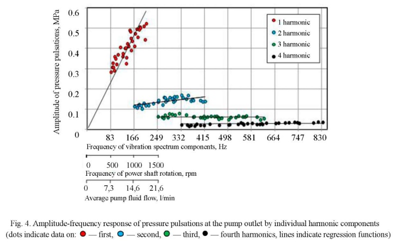
The analysis of the oscillogram, spectrogram and amplitude-frequency response of pressure pulsations showed the following: the type of process was polyharmonic steady; the number of recorded harmonics was 8, analyzed1 — 4; the amplitude range of pressure fluctuations was 0.28–0.52 MPa; the drive shaft frequency range was 500−1250 rpm, the analyzed harmonic components of the spectrum 83–833 Hz.
Fourier series expansion was used for harmonic analysis of periodic signals [7]. To decompose into a Fourier series, sections of the pressure oscillogram measured relative to the reference signal at the rotor frequency were used, i.e., one section of the oscillogram was extracted for a full rotation of the rotor. The reference signal was recorded at a fixed gear position, set at the beginning of recording the pressure waveform for five bench systems. In this way, the amplitude-frequency (FRF) Ak(ω) and phase-frequency (PFC) φk(ω) characteristics were determined.
Calculation of the spectrum of excited vibrations in various bench systems and determination of approximating for individual harmonic components of pressure fluctuations
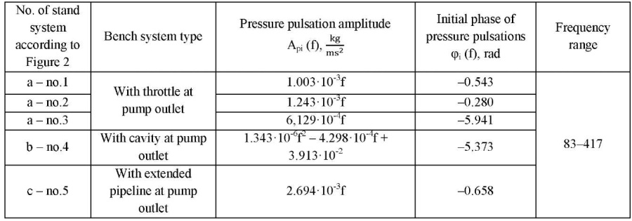
Based on the experimental determination of pressure in five bench systems: with a throttle (no.1–3), with a cavity (no.4) and an extended pipeline (no.5) at the pump outlet, the spectra of excited vibrations were calculated. Table 2 shows the regression functions of the amplitudes Ap(f) and the initial phases of pressure pulsations for the 1st harmonic.
Table 2
Regression functions of amplitudes and initial phases of pressure fluctuations
Calculation of the dynamic characteristics of the pump
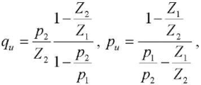
To calculate the dynamic characteristics of the pump (impedance and pulsation performance of the source), it is required to conduct an experiment with at least two dynamic loads2. Therein, according to the model of an equivalent source of flow fluctuations refined by the authors using analytical dependences pi(f) and Zi(f) from Tables 1 and 2, the pump impedance is calculated from the formula:
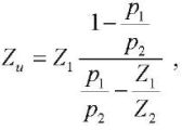 (4)
(4)
where Zu — pump impedance;
 — pump impedance module;
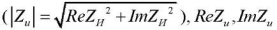 — real and imaginary part of pump impedance;
φu — pump impedance argument;
Z1, Z2 — input impedance of dynamic loads no. 1–2;
 — impedance arguments of dynamic loads no. 1–2;
p1, p2 — pressure pulsations behind the pump in bench system no. 1–2;
 — amplitudes of flow pulsations behind the pump in bench system no. 1–2;
φ1, φ2 — initial phases of pressure pulsations of dynamic loads no. 1–2.
Then, using the analytical dependences from Tables 1 and 2, the pulsation capacity of the pump was determined according to the model of an equivalent source of vibrations refined by the authors (variable component of volumetric flow qи and pressure pи):
 (5)
(5)
where qu, pu — variable component of the volume flow 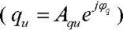 and pressure
 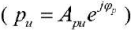 of the pump;
Aqu, Apu — pump flow and pressure pulsation amplitude;
φq, φp — argument of the variable component of the volume flow and pressure of the pump.
Of the calculated characteristics according to ESFF (qu(f)) and ESPF (pu(f)) models, using formula (5), only one will be stable, since the equivalent oscillation source has an independent dynamic characteristic only for one of the parameters (pulsating flow or pressure).
The calculation of impedance Zu and the variable component of the volume flow qи of the pump was carried out according to formulas (4)–(5) for five dynamic loads, i.e., using ten different combinations of these loads: “1_2”, “1_3”, “2_3”, “1_4”, “2_4”, “3_4”, “1_5”, “2_5”, “3_5”, “4_5” (Table 1).
For further calculation and analysis, a characteristic of the pump flow pulsation amplitudes Aqи was obtained from ten flow pulsation amplitude curves. The values of the amplitudes Aqи (at each frequency) were calculated using the formula from source [8]:
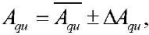
where  — average amplitude of pulsating flow;
ΔAqи — confidence interval of the amplitude of pump flow pulsations 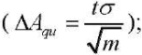
σ — standard deviation of the amplitude of the pulsating flow rate from the average value;
m — number of dynamic load combinations (m = 10);
t — Student's coefficient (t = 2,262, was calculated for the confidence level 0.95).
The confidence interval of amplitudes ΔAqи was formed from errors (instrument and method) and the degree of dependence of the dynamic characteristics of the pump Aq(f) on the bench system. The instrument error consisted of the error of determining the pressure and phases, the method error included the error of the unaccounted influence of the dynamic properties of the drive mechanical system.
The phases of flow pulsations φq and their deviations were calculated in a similar way. When calculating the phases, combinations “1_2” and “1_5” were excluded due to the degeneration of the variable component of the volume flow of the pump qи when using close values of characteristics at the same frequency: φ1 ≈ φ2 and β1 ≈ β2.
The results of calculating the intrinsic dynamic characteristic of the pump in the form of pulsation performance and impedance are shown in Figure 5. Phases, for convenience, are presented in degrees.
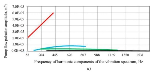
The amplitude of the flow pulsations at the 1st harmonic has a monotonically increasing character. With an increase in the harmonic number, the slope of the flow pulsation amplitude curve decreases to an almost constant value to the 4th harmonic. The values of amplitudes Aq at the higher harmonics are by an order of magnitude less than at the 1st harmonic.
The pump impedance module at the 1st harmonic has a monotonically increasing character.
To evaluate the realized dynamic loads, the criterion of matching the impedance module  of the oscillation source and the input impedance module of the dynamic load
  was used [99, 10]. The impedance modules should be comparable
  so that the quantitative values of the dynamic characteristics of the pump were determined with minimal error. For comparison, ratio
  was used. At
 , the dynamic load was considered consistent with the source.
Due to the difference in the curve shapes of the pump impedance modules and dynamic loads in the frequency range of 83–417 Hz, it was rational to use average ratio  , that provided considering the contribution of most of the frequency range, i.e., ratio
 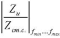 according to the 1st harmonic would be:
That is, the dynamic loads of bench systems no. 1, 2 were the most consistent with the source of vibrations. Thus, the dynamic characteristic of the pump, calculated using dynamic loads of bench systems no.1, 2 (“1_3”, “2_3”, “1_4”, “2_4”, “1_5”, “2_5”) was determined with a minimum error.
Evaluation of the stability of the dynamic characteristics of the pump from the characteristics of bench systems
Stability of the dynamic characteristics  of the pump was evaluated using mathematical statistics tools [8]. Thus, the stability of the characteristic Aqи was estimated through calculating the ratio of the confidence interval
  at frequency f to the average value of the characteristic
  at this frequency3. The resulting relative deviation Δq should not exceed the specified deviation Δдопq:
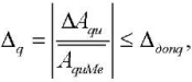
where  — average median value of the amplitude of pump flow pulsations;
Δдопq — specified relative deviation of the pump flow rate pulsation amplitude from the average value.
With relative deviation  the stability of characteristic Aqи was maximum. Based on the experience of other researchers, it is preferable to select value Δдопq within 5–30 % [11–17].
For a single-digit evaluation of the dynamic characteristics of the pump, it is rational to use the value of the relative deviation. The calculation of such a value is possible through estimating the average median value of relative deviations in the frequency range of each harmonic
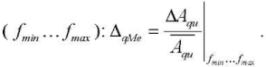
Value ΔqMe is efficiently used, if
![]() i.e., when the confidence interval ΔAqи does not exceed 30% of the average amplitude of pulsating
i.e., when the confidence interval ΔAqи does not exceed 30% of the average amplitude of pulsating 
The results of assessing the stability of the dynamic characteristics of the pump from the characteristics of the bench systems4 were: according to the 1st harmonic — 2 %, according to the 2nd — 8 %, according to the 3rd — 15 %, according to the 4th — 48 %. The results of the calculation of the dynamic characteristics of the pump showed that for four harmonics in the frequency range of 500–2500 rpm, the gear pump under study should be considered according to the model of an equivalent source of flow fluctuations.
Checking the applicability of the pump model used as an equivalent source of flow fluctuations
To test the developed approach for evaluating the dynamic characteristics of the pump, a calculated determination of pressure pulsations in bench systems with a throttle, a cavity and an extended pipeline at the pump outlet was performed. Using the found dynamic characteristics of the pump, the amplitudes of pressure pulsations in the analyzed bench systems were calculated, which were compared to the experimental ones. The results of the calculation of amplitudes Ap(f) in a bench system with an extended pipeline are presented below. The amplitudes of pressure pulsations pi were calculated in accordance with the ESFF model from the formula:
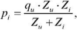 (6)
(6)
The results of calculating the amplitudes of pressure pulsations behind the pump are shown in Figure 6. The dotted line indicates the amplitudes obtained experimentally, and the solid line — calculated from formula (6).
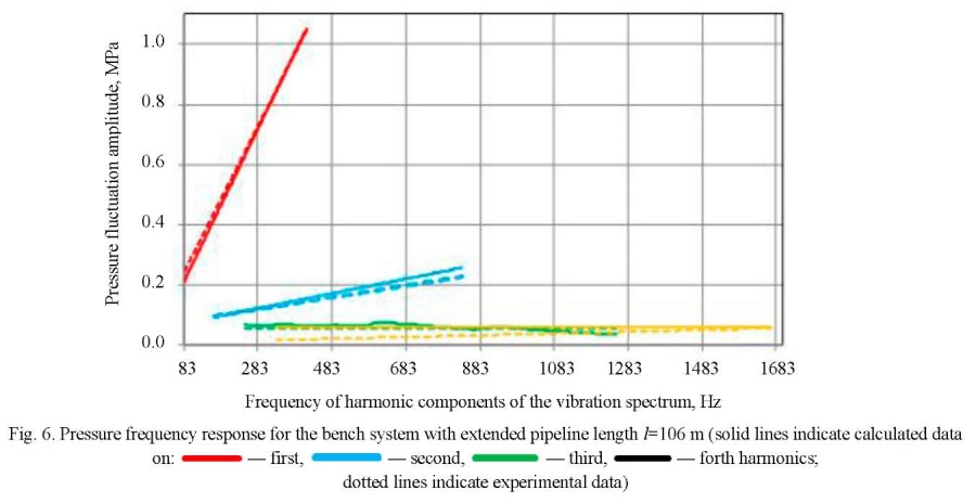
Convergence of the results of the verification calculation was evaluated according to the formula of deviation of the difference between the experimental and calculated values from the experimental data. The results of the test calculation for the bench systems with a throttle, a cavity and an extended pipeline at the pump outlet showed that according to the 1st harmonic, the relative deviation from the experimental data for the considered bench systems did not exceed 10 %, the minimum relative deviation was characteristic of a bench system with an extended pipeline at the pump outlet — 2%. The amplitudes of the pressure pulsations of the 2nd–4th harmonics were within the corridor calculated from the formula 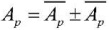 (where
  — the average amplitude of the pulsating pressure).
Discussion and Conclusions. Methodology for calculating dynamic characteristics of the pump in the form of an equivalent source of fluid flow fluctuations was implemented on the example of a gear pump with a capacity of 14 cm3/rev using special bench systems developed by the authors and an updated model of impedance and pulsation flow rate. It was shown that the investigated gear pump of external gearing was rationally considered according to the model of an equivalent source of flow fluctuations. The proposed approach was verified in the form of calculation of pressure pulsation amplitudes in the bench systems and comparison to experimental values. The deviation of the calculated amplitudes of pressure pulsations from the experimental values did not exceed 10%. It is worth noting that the impact on the dynamic characteristics of the gear pump of the drive mechanical system and the wear of the gear pump parts remained outside the scope of the review. Based on the work carried out, it was possible to formulate directions for the development of the proposed approach:
Here, it is required to expand the nomenclature of the tested volumetric pumps for the entire class of volumetric displacement machines to confirm the operability of the proposed approach.
1. It is assumed in the work that the extreme highest analyzed harmonic in amplitude should not be more than 5 % of the amplitude of the first harmonic.
2. For a sufficient sample size, it was required to use at least four dynamic loads Zij, that form six non-repeating (including i ≠ j) combinations: Z12 , Z13, Z14, Z23, Z24, Z34.
3. Stability of other intrinsic characteristics of the pump is evaluated similarly.
4. It is required to consider the method error of the approach and the instrument error of determining the pressure.
1. Рыбак, А. Т. Моделирование и экспериментальные исследования гидромеханической системы со знакопеременной нагрузкой / А. Т. Рыбак, В. П. Жаров, Р. А. Фридрих // Вестник Донского государственного технического университета. — 2006. — Т. 6, № 1. — С. 17–25.
2. Рыбак, А. Т. Объемная жесткость и ее влияние на динамику гидромеханической системы / А. Т. Рыбак // Вестник Донского государственного технического университета. — 2006. — Т. 6, № 3. — С. 200–207.
3. Озерский, А. И. Применение подхода Лагранжа к решению задач динамики гидравлических систем гидроприводных и теплоэнергетических установок / А. И. Озерский // Вестник Донского государственного технического университета. — 2010. — Т. 10, № 6. — С. 914–925.
4. Формирование динамических свойств трубопроводных цепей / Н. Д. Быстров, А. Г. Гимадиев, А. Н. Головин [и др.]; под ред. В. П. Шорина. — Самара : Изд-во Самар. ун-та, 2020. — 328 с.
5. The equivalent circuits Thévenin and Norton / M. Staniloiu, H. Popescu, G. Rezmeriţă, M. Iordache // The Scientific Bulletin of Electrical Engineering Faculty. — 2021. — Vol. 21. — P. 40–48.
6. Thévenin, L. Sur un nouveaux théorème d’électricité dynamique / L. Thévenin // Comp. Rendus hebdomadaires des Séances de l’Académie des Sci. — 1883. — Vol. 97. — P. 159–161.
7. Generalized Functions and Fourier Analysis / M. Oberguggenberger, J. Toft, J. Vindas, P. Wahlberg (ed.) — Springer International Publishing AG, 2017. — 276 p.
8. Handbook of Mathematics, 5th ed. / I.N. Bronshtein, K.A. Semendyayev, G. Musiol, H. Mühlig. — Berlin: Springer, 2015. — 1207 p.
9. Артюхов, А. В. Особенности частотных испытаний гидравлических насосов / А. В. Артюхов, Л. И. Брудков // Вибрационная прочность и надежность двигателей и систем летательных аппаратов: межвуз. сб. науч. тр. — Куйбышев : КуАИ, 1982. — Вып. 9. — С. 12–17.
10. Sundararajan, D. Introductory circuit theory / D. Sundararajan. — Switzerland : Springer, 2020. — 297 p. https://doi.org/10.1007/978-3-030-31985-4
11. Ichiyanagi, T. The temperature characteristics of flow ripple and source impedance in an external gear pump / T. Ichiyanagi, T. Nishiumi, Sh. Nakagawa // In: Proc. 10th JFPS Int. Symposium on Fluid Power, 2017. — 5 p.
12. Артюхов, А. В. Методика определения динамических характеристик гидравлических насосов / А. В. Артюхов, В. П. Шорин // Динамические процессы в силовых и энергетических установках летательных аппаратов аппаратов : межвуз. сб. науч. тр. — Куйбышев : КуАИ, 1988. — С. 70–77.
13. Jinghao Liu. Source flow ripple and source impedance measurement for different hydraulic pumps / Jinghao Liu // In: Proc. 47th Int. Congress and Exposition on Noise Control Engineering (InterNoise 2018). — Chicago, Illinois, 2018. — 7 p.
14. Liselott Ericson. On Fluid Power Pump and Motor Design – Tools for Noise Reduction. PhD Thesis / Liselott Ericson. — Linköping University, Sweden, 2011. — 130 p.
15. Bramley, C. Comparison of methods for measuring pump flow ripple and impedance / C. Bramley, D. N. Johnston // In: Proc. ASME/BATH 2017 Symposium on Fluid Power and Motion Control. — 2017. — 11 p. http://dx.doi.org/10.1115/FPMC2017-4223
16. Jinghao Liu. Hydraulic Fluid-Borne Noise Measurement and Simulation for Off-Highway Equipment / Jinghao Liu, Sanghoon Suh, Yuzhen Yang // In: Proc. 2017 SAE/NOISE-CON Joint Conf. (NoiseCon 2017), Grand Rapids, MI. —2017. — Vol. 9. — P. 435–443.
17. Theoretical and experimental studies of a switched inertance hydraulic system including switching transition dynamics, non-linearity and leakage / Min Pan, Nigel Johnston, Andrew Plummer [et al.] // Proc. Institution of Mechanical Engineers, Part I: Journal of Systems and Control Engineering. — 2014. — Vol. 228. — P. 802–815. https://doi.org/10.1177/0959651814548299
34, Moskovskoye Shosse, Samara
34, Moskovskoye Shosse, Samara
Sanchugov V.I., Rekadze P.D. Determination of the dynamic characteristics of a gear pump by the load variation method using special bench systems. Advanced Engineering Research (Rostov-on-Don). 2022;22(2):130-141. https://doi.org/10.23947/2687-1653-2022-22-2-130-141


Advanced Engineering Research (Rostov-on-Don)
ISSN 2687-1653 (Online)
Contact with: Publisher / Editorial Office of the Journal
Publisher: Don State Technical University - DSTU, Rostov-on-Don, Russia - https://donstu.ru/en/
Editor-in-Chief: Alexey N. Beskopylny, Dr.Sci. (Eng.), Professor, Vice-Rector, Don State Technical University (Rostov-on-Don, Russia)
Don State Technical University
1, Gagarin Sq., Rostov-on-Don, 344003, Russia
tel.: +7 (863) 2738-372, e-mail: vestnik@donstu.ru
16+
Processing of personal data


