


Contents
Scroll to:
https://doi.org/10.23947/2687-1653-2023-23-4-365-375
EDN: JBOFSU
Scroll to:
Introduction. When numerically solving problems of elasticity theory in a three-dimensional formulation by the finite element method, finite elements (FE) in the form of parallelepipeds, prisms and tetrahedra are used. Regularly, the construction of stiffness matrices of volumetric FE is based on the principle of isoparametricity, which involves the Lagrange polynomials to approximate the geometry and displacements. In computational practice, the most widespread FE are the so-called multilinear isoparametric FE with a linear law of approximation of displacements. The main disadvantage of these elements lies in the “locking” effect when modulating bending deformations. Moreover, the error of the numerical solution increases drastically in the case when the structure, in comparison to conventional deformations, undergoes significant displacements as a rigid whole. Long-term experience in solving problems of deformable solid mechanics by the finite element method has shown that existing volumetric FE have slow convergence, specifically, when modeling bending deformations of plates and shells. This study aims at constructing stiffness matrices of multilinear volumetric FE of increased accuracy allowing for rigid displacements based on the double approximation method.
Materials and Methods. The mathematical apparatus of the double approximation method based on the principle of a separate representation of the distribution functions of displacements and deformations inside the element, was used to construct the stiffness matrices of volumetric FE. The storage and processing of the resulting system of equations was implemented in algorithmic terms of sparse matrices. Software development and computational experiments were carried out using the Microsoft Visual Studio 2013 64-bit computing platform and the Intel ® Parallel Studio XE 2019 compiler with the integrated Intel ® Visual Fortran Composer XE 2019 text editor. Visualization of the calculation results was performed using the descriptor graphics of the MATLAB computer mathematics package. A large eight-node SOLID185 CE of the ANSYS Mechanical software complex was used as a test sample.
Results. Mathematical tool and software were developed to study the stress-strain state of massive structures under various types of external actions. The authorized application software package was verified on test examples with known analytical solutions. It has been shown that the constructed FE accurately satisfy the basic requirements for finite element modeling of spatial problems of elasticity theory.
Discussion and Conclusion. The performed testing of the developed mathematical and program toolkit has shown that the finite elements constructed on the basis of the double approximation method can successfully compete with similar SOLID185 volumetric elements of the ANSYS Mechanical software complex. The proposed elements can be integrated into domestic import-substituting software systems that implement the finite element method in the form of the displacement method.
Gaidzhurov P.P., Saveleva N.A. Application of the Double Approximation Method for Constructing Stiffness Matrices of Volumetric Finite Elements. Advanced Engineering Research (Rostov-on-Don). 2023;23(4):365-375. https://doi.org/10.23947/2687-1653-2023-23-4-365-375. EDN: JBOFSU
Introduction. In finite element modeling of the stress-strain state of massive bodies, volumetric finite elements (FE) in the form of parallelepipeds (hexahedra), prisms and tetrahedra are used, the construction of stiffness matrices of which is usually performed using isoparametric technology [1-5]. At the same time, it is known that multilinear isoparametric FE, when using a single-layer scheme, do not satisfactorily model bending deformations even with a significant thickening of the mesh [6][7]. The core of this problem is the effect of “locking” the element due to the so-called deformation of the “false shift” [8][9]. To “improve” isoparametric FE, an apparatus of incompatible elements created through introducing additional out-of-node degrees of freedom, or auxiliary approximating polynomials, is used [8]. At the same time, the most effective way to solve the problem of “jamming” of the FE is the use of the moment scheme of the finite element method, whose theoretical foundations were developed by A.S. Sakharov [7]. Subsequently, this approach was called the double approximation method (DAM) [6]. Conceptually, the DAM is based on a separate representation of the distribution functions of displacements and deformations inside the element. The objective of this study is to construct on the basis of MDA and test new volumetric multilinear FE that allow simulating the behavior of various structures under different types of external actions.
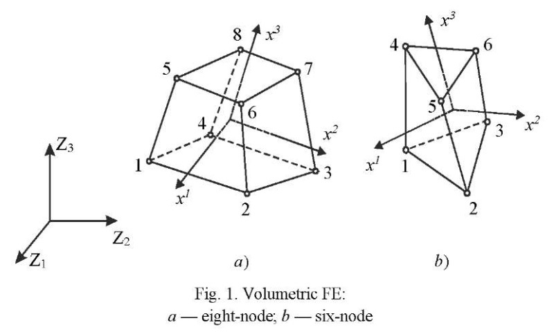
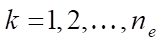
Materials and Methods. Let us consider a family of volumetric FE consisting of eight-node and six-node elements in global Cartesian axes  ,
,  = 1, 2, 3 (Fig. 1). Geometry and displacements of the FE are presented in the following form:
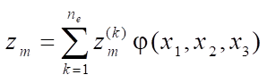 ;
;
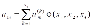 ,
,
where
 ,
,  — nodal coordinates and displacements;
 — “shape functions” representing the product of one-dimensional Lagrange linear polynomials;
 ,
,  ,
,  — local, in general, nonorthogonal coordinates of FE;
 — number of element nodes.
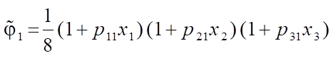
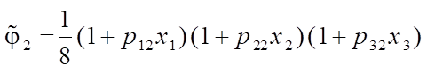
For the basic eight-node element (Fig. 1 a)  = 8, “shape functions” are defined by formula:
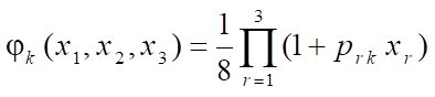 , (1)
, (1)
Here,  — coordinates of nodes in local axes. We set values
  in matrix form:
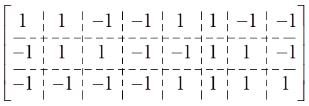 .
.
The relationship between the covariant components of the strain tensor in the local basis and displacements in the global axes has the form [7]:
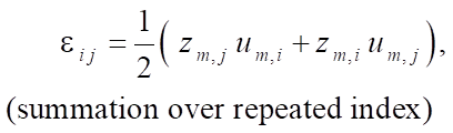
where
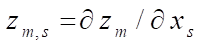 ;
;
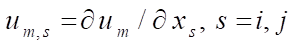 .
.
The relationship between vector of deformations  and vector of nodal displacements
  is represented in matrix form:
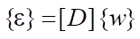 ,
,
where block matrix:
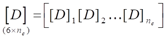 ;
;
submatrix:
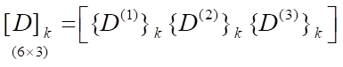 ,
,
 .
.
Expressions for the vector columns of the considered FE have the following form [10]: an eight-node element (Fig. 1 a)
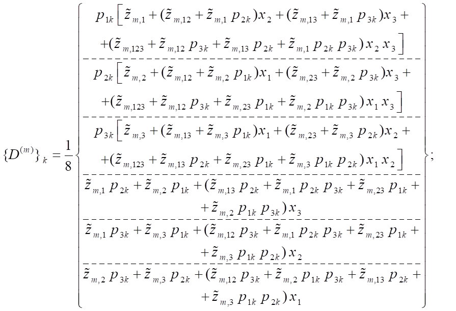 (2)
(2)
Six-node element (Fig. 1 b)
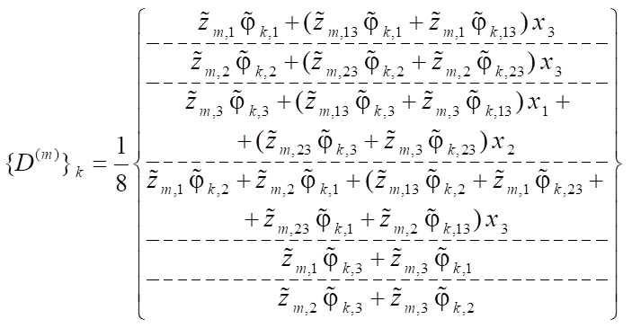 . (3)
. (3)
The notation is introduced here:
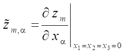 ,
,
 ;
;
 .
.
 ;
;
 ;
;
 .
.
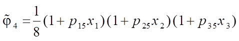
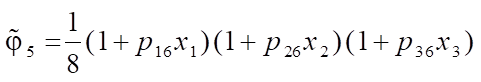
Expressions for “shape functions  of a six-node FE obtained on the basis of the polynomial (1) using the degeneration principle have the following form:
 ;
;
 ;
;
 ;
;
 ;
;
 ;
;
 .
.
Formulas (2) and (3) were the basis for constructing stiffness matrices of the FE under study. The corresponding software was developed on the basis of the Microsoft Visual Studio computing platform and the Intel® Parallel Studio XE compiler with the built-in Intel® Visual Fortran Composer XE text editor. The processes of storing and processing the global stiffness matrix were implemented in terms of sparse matrices [11]. To visualize the results of calculations, the descriptor graphics of the MATLAB computer system was used.
Research Results. The investigation on the accuracy and convergence of the developed finite element algorithm was carried out on test examples with an analytical solution. The test examples show numerical solutions obtained using the developed elements and the SOLID185 element of the ANSYS Mechanical software package similar in dimension [5][11]. Below are examples selected so that they contain a combination of bending deformations and rigid displacements of FE.
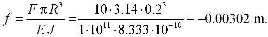
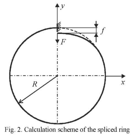
Example 1. A spliced ring rigidly fixed in one section and loaded with concentrated force at the free end. The design scheme of the ring is shown in Figure 2. Initial data: average radius  = 0.2 m; cross-sectional dimensions 0.2×0.2 cm; modulus of elasticity
  = 1011 Н/m2; Poisson's ratio n = 0.3; concentrated force
  = 10 Н.
The deflection at the point of application of force according to the theory of curved rods (exact solution) is [7]:
The convergence results are presented in Table1.
Table 1
Convergence results for the spliced ring
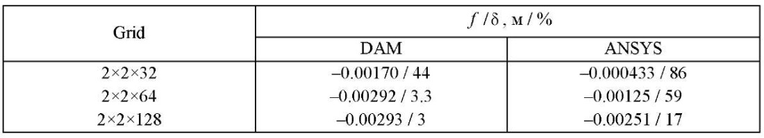
Table 1 shows the value of deflection f in the numerator, and relative error  in the denominator.
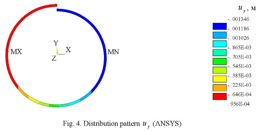
The visualization of displacements  , obtained on the basis of DAM and ANSYS on a 2×2×64 grid is shown in Figures 3 and 4. Note that the field of vertical displacements obtained using ANSYS does not reflect the zones with extreme value
  = –0.00314 m shown in Figure 3 by the arrow.
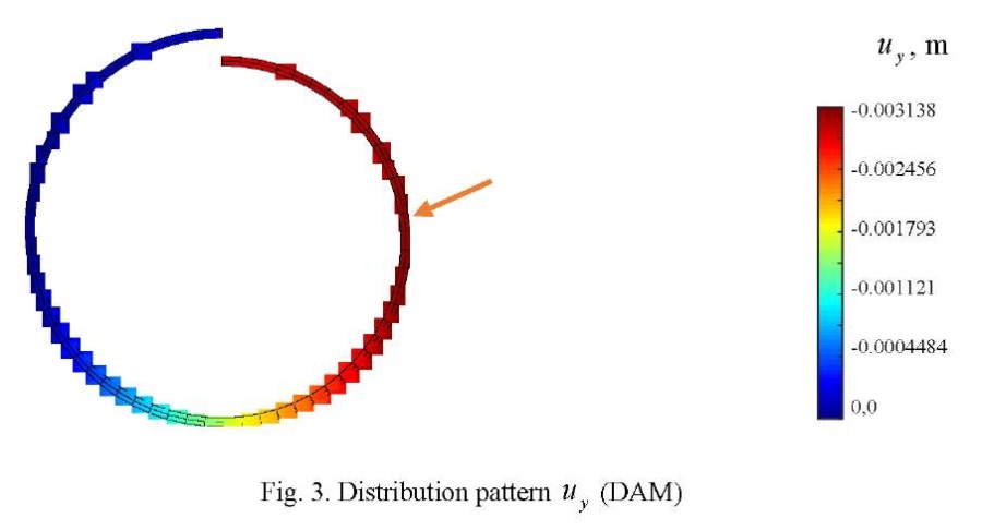
In this example, the importance of taking into account rigid displacements is particularly clearly seen.
Example 2. A square plate, rigidly pinched along the contour and loaded with a uniformly distributed load. Source data: side length стороны  = 1 m; thickness
  = 0.01 m; elasticity modulus
  = 105 Н/m2; Poisson's ratio
  = 0.25.
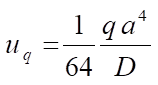
The exact value of the deflection in the center of the plate is determined by formula [12]:
 ,
,
where
 = 0.00126;
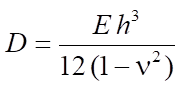 — cylindrical stiffness;
 = 0.00888889 Н/m2 — distributed load intensity.
Exact value  (in meters) is equal to coefficient
  .
.
In this example, ¼ part of the plate was considered taking into account the conditions of symmetry. The convergence results in the form of graphs  for single-layer and double-layer models are shown in Figures 5 and 6. Here and further, layers mean the breakdown of the plate into FE by thickness. In these figures, values 1, 2, 3, 4 of parameter
  1, 2, 3, 4 correspond to the grids: 4×4, 8×8, 16×16, 32×32. The graphs below show the results of the solution obtained using ANSYS (line 1) and DAM (line 2). The horizontal line indicated by the number 3 corresponds to the exact solution.
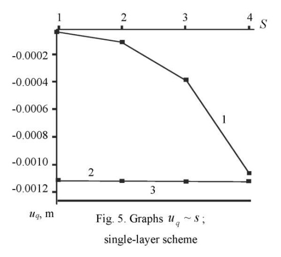
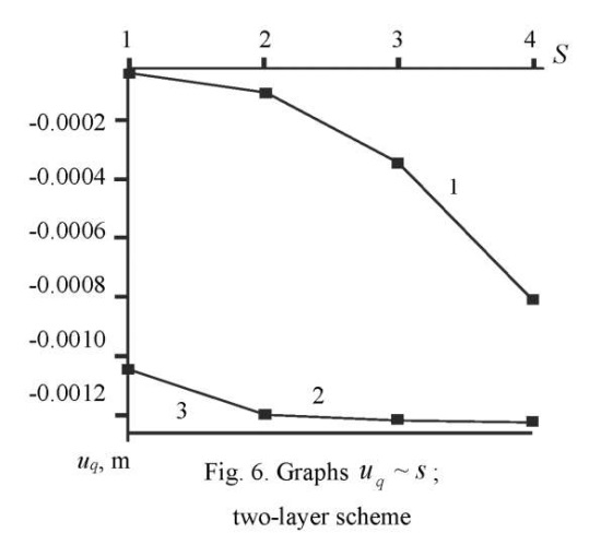
It follows from Figure 5 that with a single-layer breakdown scheme, the relative error values on a 32×32 grid are: SOLID185 — 16%; DAM - 10.5%. When using a two-layer scheme (Fig. 6) on a 32×32 grid, we have: SOLID185 — 36%; DAM — 2.8%.
FE patch testing was performed for the 16×16×2 breakdown scheme with grid distortion (Fig. 7). The patch test results in the form of deflection distribution patterns  are shown in Figures 8 and 9.
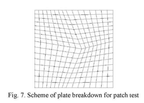
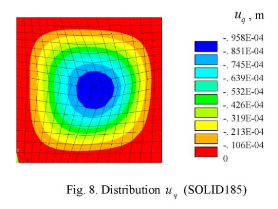
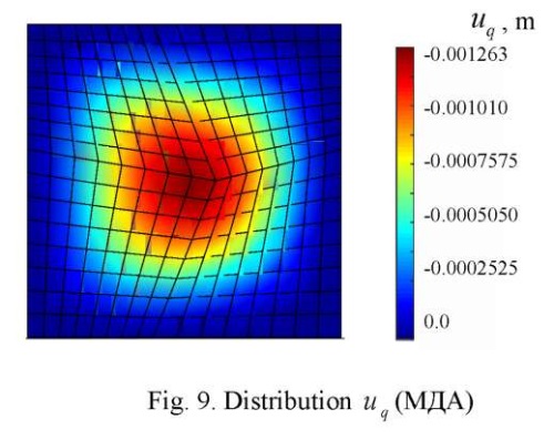
As can be seen from the Figures, the distortion of the grid, when using SOLID185, causes a more noticeable asymmetry of field  , than when using DAM. At the same time, the value of the maximum deflection for FE DAM
  = 0,001263 m coincides with the exact solution.
Example 3. A round plate, rigidly pinched along the contour and loaded with a uniformly distributed load. Radius and thickness of the plate: R = 1 m; h = 0.01 m. The mechanical constants are similar to the data in Example 2.
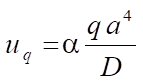
The exact value of the deflection in the center of the plate is determined by formula [12]:
 .
.
At the value of the intensity of distributed load q = 0.00888889 Н/m2 value uq = 0.01563 m.
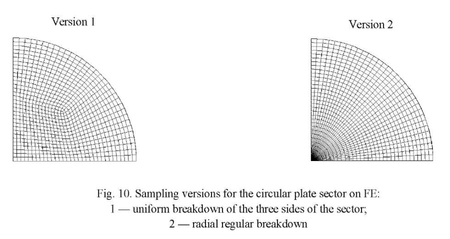
In the testing process, two versions of sampling the ¼ part of the plate (sector) on FE were used. In the first version, the three sides of the sector were divided into an equal number of segments. The second version was based on a radial regular pattern of sector breakdown. In this case, the number of elements along the radius and the circular part of the sector was assumed to be the same. The considered sector discretization versions for a 32×32 grid are shown in Figure 10.
The convergence results in the form of graphs  for sampling the ¼ part of the plate according to version 1 with single-layer and two-layer breakdown schemes are presented in Figures 11, 12, and Figures 13, 14, respectively
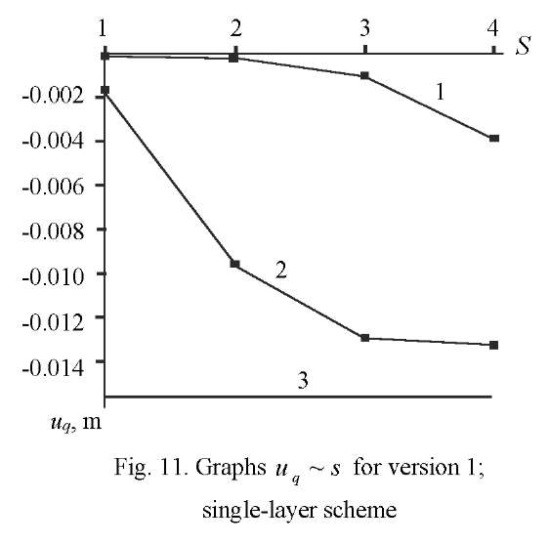
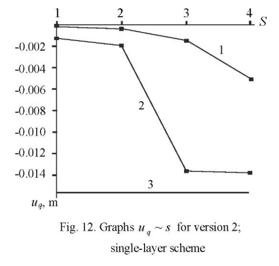
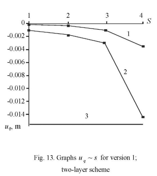
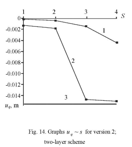
In these figures, values 1, 2, 3, 4 of parameter S 1, 2, 3, 4 correspond to the grids: 4×4, 8×8, 16×16, 32×32. As in Example 1, line 1 corresponds to a SOLID185-based solution, and line 2 corresponds to DAM. The horizontal line indicated by the number 3 corresponds to the exact solution.
It follows from the above graphs that an element constructed according to the moment scheme on a 32×32×2 grid of version 2 has a relative error of 4 %.
Visualization patterns of the field of distribution of vertical displacements  for DAM and SOLID185 with a radial layout of the ¼ plate (32×32×2 grid) are shown in Figures 15 and 16, respectively.
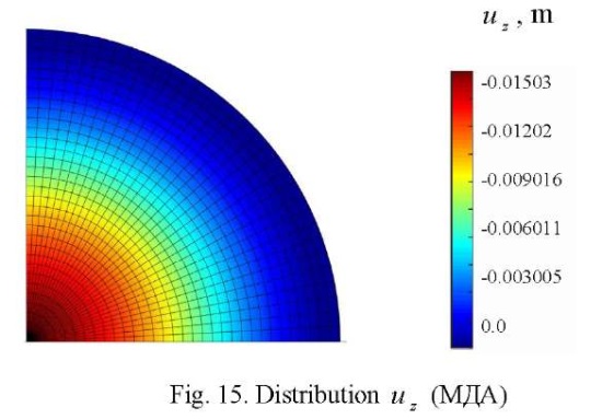
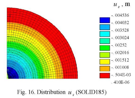
From the above figures, it can be seen that despite the qualitative coincidence of patterns  , relative errors for the maximum deflection are: DAM — 3.8%; SOLID185 — 71%. Such a significant error, when using SOLID185, is because the developers applied “shape functions” similar to the functions used for the eight-node element to approximate the geometry and displacements of the six-node element, i.e., without the “degeneration” principle [7].
Discussion and Conclusion. Stiffness matrices of volumetric multilinear finite elements constructed on the basis of the double approximation method make it possible to simulate the stress-strain state of building structures of arbitrary geometry under various types of external actions. The fundamental difference between the proposed concept and the previously known finite element technologies is that the displacements, in this case, are set in global coordinates, and the components of the strain tensor are determined in local, in general, nonorthogonal axes.
The test examples show that the volumetric finite elements, constructed by the double approximation method, have stable convergence and compete successfully with an element of a similar type SOLID185 of the ANSYS Mechanical computing complex.
The developed mathematical software can be introduced into domestic import-substituting software complexes implementing the finite element method in the form of the displacement method.
1. Zienkiewicz OC, Taylor RL. The Finite Element Method, Fifth edition. Oxford, UK: Butterworth-Heinemann; 2000. 708 p.
2. David V Hutton. Fundamentals of Finite Element Analysis. New York, NY: The McGraw Hill Companies; 2004. 494 p. URL: https://wp.kntu.ac.ir/fz_kalantary/Source/Finite%20element%20method/BooksNumerical/Fun-damentals%20of%20Finite%20Element%20Analysis,%20Hutton%20(2004).pdf (accessed: 15.08.2023).
3. Daryl L Logan. A First Course in the Finite Element Method. New York, NY: CL Engineering; 2011. 836 p. URL: https://kntu.ac.ir/DorsaPax/userfiles/file/Mechanical/OstadFile/dr_nakhodchi/DarylL.LoganAFirstCourse.pdf (accessed: 15.08.2023).
4. Carlos A Felippa. Introduction to Finite Element Methods. Boulder, CO: University of Colorado; 2004. 791 p. URL: https://vulcanhammernet.files.wordpress.com/2017/01/ifem.pdf (accessed: 15.08.2023).
5. Saeed Moaveni. Finite Element Analysis. Theory and Application with ANSYS. Hoboken, NJ: Prentice Hall; 1999. 527 p. URL: http://ftp.demec.ufpr.br/disciplinas/TM738/Livros/Finite%20Element%20Analysis,%20Theory%20and%20application%20with%20ANSYS,%20.pdf (accessed: 15.08.2023).
6. Golovanov AI, Tyuleneva ON, Shigabutdinov AF. Finite Element Method in Statics and Dynamics of Thin-Walled Structures. Moscow: Fizmatlit; 2006. 391 p. (In Russ.)
7. David V Hutton. Fundamentals of Finite Element Analysis. New York, NY: McGraw-Hill; 2004. 505 p. URL: https://wp.kntu.ac.ir/fz_kalantary/Source/Finite%20element%20method/BooksNumerical/Fundamentals%20of%20Finite%20Element%20Analysis,%20Hutton%20(2004).pdf (accessed: 15.08.2023).
8. Miguel Luiz Bucalem, Klaus-Jürgen Bathe. The Mechanics of Solids and Structures – Hierarchical Modeling and the Finite Element Solution. New York, NY: Springer; 2011. 597 р.
9. Jacob Fish, Ted Belytschko. A First Course in Finite Elements. Hoboken, NJ: Wiley; 2007. 319 p.
10. Gaidzhurov PP. Finite Elements of Increased Accuracy for Solving 3D Problems of Elasticity Theory. University News. North-Caucasian Region. Technical Sciences Series. 2003;(1):54–57. URL: https://cyberleninka.ru/article/n/konechnye-elementy-povyshennoy-tochnosti-dlya-resheniya-trehmernyh-zadach-teorii-uprugosti/viewer (accessed: 15.08.2023). (In Russ.)
11. Chigarev AV, Kravchuk AS, Smalyuk AF. ANSYS for Engineers. Moscow: Mashinostroenie; 2004. 512 p. URL: https://www.researchgate.net/profile/AKravchuk/publication/262729610_ANSYS_dla_inzenerov/links/0f31753b4294b13fc9000000/ANSYS-dla-inzenerov.pdf (accessed: 15.08.2023). (In Russ.)
12. Madenci E, Guven I. The Finite Element Method and Applications in Engineering Using ANSYS. New York, NY: Springer; 2015. 664 p.
Peter P. Gaidzhurov, Dr.Sci. (Eng.), Professor of the Structural Mechanics and Theory of Structures Department
1, Gagarin sq., Rostov-on-Don, 344003
Nina A. Saveleva, Senior lecturer of the Structural Mechanics and Theory of Structures Department
1, Gagarin sq., Rostov-on-Don, 344003
Gaidzhurov P.P., Saveleva N.A. Application of the Double Approximation Method for Constructing Stiffness Matrices of Volumetric Finite Elements. Advanced Engineering Research (Rostov-on-Don). 2023;23(4):365-375. https://doi.org/10.23947/2687-1653-2023-23-4-365-375. EDN: JBOFSU


Advanced Engineering Research (Rostov-on-Don)
ISSN 2687-1653 (Online)
Contact with: Publisher / Editorial Office of the Journal
Publisher: Don State Technical University - DSTU, Rostov-on-Don, Russia - https://donstu.ru/en/
Editor-in-Chief: Alexey N. Beskopylny, Dr.Sci. (Eng.), Professor, Vice-Rector, Don State Technical University (Rostov-on-Don, Russia)
Don State Technical University
1, Gagarin Sq., Rostov-on-Don, 344003, Russia
tel.: +7 (863) 2738-372, e-mail: vestnik@donstu.ru
16+
Processing of personal data


