


Contents
Scroll to:
https://doi.org/10.23947/2687-1653-2024-24-1-66-77
Scroll to:
Introduction. The problem of improving the manufacturing of high-precision products is currently becoming a key one, since the requirements for them are constantly being tightened. Maintaining assembly quality and accuracy is an important aspect of manufacturing precision products. Standard approaches to this process do not always have sufficient versatility. Existing studies that aim to develop universal approaches, such as end-to-end production design or the application of parallel engineering principles, also have a number of shortcomings. These include the fact that the given approaches do not fully take into account information about the technology capabilities of a particular production when making design decisions, and do not consider the relationship between the manufacturing preparation of machining and mechanical assembly industries. That is why studies aimed at developing such universal approaches have high applicability. To solve these problems, the authors conceptually developed a set of formalized design procedures for a system of accounting requirements for the assembly of high-precision products in the design of machining processes. However, to effectively identify the numerous requirements for the assembly of high-precision products (output parameters) and select those that cannot be provided by the method of complete interchangeability (critical elements), additional research is needed. The research objective is to develop principles for identifying the output parameters of high-precision products and detecting critical elements. To achieve this goal, it is required to solve the following problems: to formulate principles for constructing generalized surface graphs of high-precision products; to develop standards for classifying output parameters and identifying critical ones.
Materials and Methods. To conduct the research, a high-precision assembly unit was selected — “Stator Package 2”. The research was carried out under real conditions of the existing multiproduct manufacture. For this assembly, a generalized surface graph was constructed, including information about the nature and sequence of surfaces, requirements for the assembly, dimensional tolerances and tolerances of shape and location, with its subsequent analysis.
Results. This paper presents the results of research on improving the enlarged block of design procedures for analyzing requirements for the assembly of high-precision products of the designed system. The paper established the relationship between the accuracy of dimensional tolerances and the tolerances of the shape and location of the surfaces of the product to which these dimensions belonged. Based on the relationship obtained, an order was determined for the unambiguous identification of critical elements.
Discussion and Conclusion. The application of this technique makes it possible to increase the reliability of the source information obtained during the implementation of an enlarged block of design procedures, as well as the validity and efficiency of identifying rational manufacturing technologies at subsequent stages of the system implementation, while providing the specified quality, accuracy of products, and reducing the complexity and cost of their manufacture.
Nazaryev A.V., Bochkarev P.Yu. Improving the Principles of Identifying Critical Requirements for the Assembly of High-Precision Products. Advanced Engineering Research (Rostov-on-Don). 2024;24(1):66-77. https://doi.org/10.23947/2687-1653-2024-24-1-66-77
Introduction. The production of modern devices and machines requires a clear organization of the assembly process with careful manufacturing preparation [1]. This requirement is particularly urgent in the manufacture of high-precision products in precision machine tool industry, aerospace industry, military-industrial complex, bearing industry, etc. [2]. In this paper, high-precision products mean such products, whose assembly process is complex due to difficulties in meeting specified requirements (critical assembly requirements, or critical elements), such as dimensional, dynamic and other characteristics, which may result in the need to manufacture a large number of spare parts and kits. This, in turn, causes an increase in the volume of work in progress and requires more time and resources to complete the assembly production process (PP) [3].
Modern technology makes it possible to improve the quality and accuracy of production, reduce material costs, and introduce resource-saving technologies. However, today there is no unified concept of an integrated approach to solving the above-mentioned problems. When assembling products, classical methods of maintaining accuracy are often used, which in most cases are not universal. They depend on the type of production and are often economically unjustified. In such cases, it is necessary to develop unique assembly approaches that take into account the specifications of a particular product and provide the required accuracy without unreasonable costs. In addition, it should be borne in mind that the traditional PP design of mechanical processing and assembly is subjective. This is primarily due to time constraints and physical capabilities, which make it impossible for a person to compete with modern computing technology [4]. To solve these problems, it is needed to develop unique approaches that combine various aspects of production and assembly of products, as well as taking into account economic factors. Only a comprehensive solution can provide achieving optimal results and effectively cope with the tasks set.
Currently, a system of automated process planning (SAPP) has been conceptually developed [5]. Nevertheless, the weakness of this automated system is the lack of correlation between the multiple-alternate design of the manufacturing process for parts included in the assembly unit and the requirements for the technology and accuracy of assembly of a high-precision assembly unit, based on which it is possible to efficiently solve the problem of reducing the volume of work in progress and the cost of assembly. At the same time, the correlation between design and manufacturing preparation of production has not yet been fully worked out. As a result, research in this area is urgent for the modern development of mechanical assembly production systems. The objective of the article is to develop principles for identifying the output parameters of high-precision products and determining critical elements. To do this, it is needed to formulate the principles of constructing generalized graphs of surfaces of high-precision products, determine the standards for classifying output parameters and identifying critical ones from them.
Materials and Methods. To solve the above problems, a system with account for the requirements for the assembly of high-precision products in the design of manufacturing processes of mechanical processing was developed (SRPPMP) [6]. However, to provide a more comprehensive integration of this system into the SAPP structure, it is required to actively look for options of upgrading the development strategies used. This will allow us to move on to the analysis of the manufacturability of products and provide a more effective implementation of the system into the production structure.
As part of the research to improve the methodology of formalization of the block under consideration, strategies for performing the procedures of this block were formed, and the one that provides identifying the maximum number of critical elements was selected. This strategy is a combined one and matches up the advantages of the other approaches. In addition, for a more accurate calculation of dimensional chains, a special size indexing system has been introduced, which is most effective. The specified indexing is considered in detail in [7] and is not fully cited in this paper.
According to this strategy, detailed segmentation of high-precision products is performed, which provides determining the required parameters for the formation of a set of assembly requirements (MТ.С), carrying out a design dimensional analysis and, based on its results, identifying critical elements. To implement the described procedures, first, it is needed to identify those elements from the set MТ.С that satisfy the following condition:
 (1)
(1)
where Б — assembly requirements (closing links); А — component links.
The above condition makes it possible to identify those elements that cannot be provided by the method of complete interchangeability, i.e., critical elements. The specified elements are included in the corresponding subset M1. The remaining elements are provided by the method of complete interchangeability. They form subset МП.В. and are no longer considered.
 (2)
(2)
Next, it is necessary to determine methods for maintaining accuracy for each critical element and distribute them into appropriate subsets: МН.В. — critical elements provided by the method of incomplete interchangeability;
МГ.В. — critical elements provided by the method of selective assembly; МИ.П., МР.Е. — critical elements provided by compensation.
Research Results. For the distribution of critical elements into groups, a technique based on the construction of a generalized graph of surfaces of high-precision assembly units and nodes has been developed, and distribution rules have been formulated.
The classification of modules of working and connecting surfaces of parts and assembly units (PAU), proposed by Professor Bazrov B.M. [8], is shown in Figure 1.
Fig. 1. Modules of working and connecting surfaces of PAU [8]
Consider the principles of constructing a generalized graph of surfaces using the example of the assembly unit (AU) “Stator Package 2”, which is part of the high-precision “Gyromotor” product. Figure 2 shows an axonometric projection of the AU “Stator Package 2” and a schematic representation of this AU, indicating the basic assembly requirements, shape and location tolerances imposed on it, as well as the PAU of which it consists.
Fig. 2. AU “Stator Package 2”:
a — axonometric projection; b — composition and basic assembly requirements,
shape and location tolerances
Figure 3 shows a sketch of the AU “Stator Package 2”, on which the surfaces of the composite PAU are numbered, and a code is indicated for each surface in accordance with the requirements of the SAPP [9] (Table 1).
Based on the information obtained about the nature and sequence of the PAU surfaces, a graph of the AU surfaces “Stator Package 2” is constructed. In this graph, the surfaces of the PAU included in the considered AU are indicated. For the surfaces of the PAU, parallel to the axis of rotation of the AU (marked “01” in the graph), the connection with this axis is conditionally shown. Additionally, the PAU surfaces that are in direct contact in the assembly unit are marked (e.g., surfaces 1.7 and 3.3 in Figure 4a). Further, the assembly requirements (dimensional chains) posed on this AU are presented on the specified graph, indicating the closing links and the directions of the constituent links. It is important to note that the components and closing links going to or from the group of contacting surfaces are assembly dimensions. Also, the graph indicates the basic shape and location tolerances required for the AU assembly (Fig. 4b). The assembly requirements and basic tolerances of shape and location are taken from Figure 2b. As a result, a generalized graph of AU surfaces “Stator Package 2” is formed.
Thus, the presented graph provides obtaining the required data on the dimensional relationships between individual surfaces (groups of surfaces) of PAU, as well as the surfaces of the mating PAU in contact with each other. The obtained data form the initial information for the further stages of the implementation of the SAPP procedures.
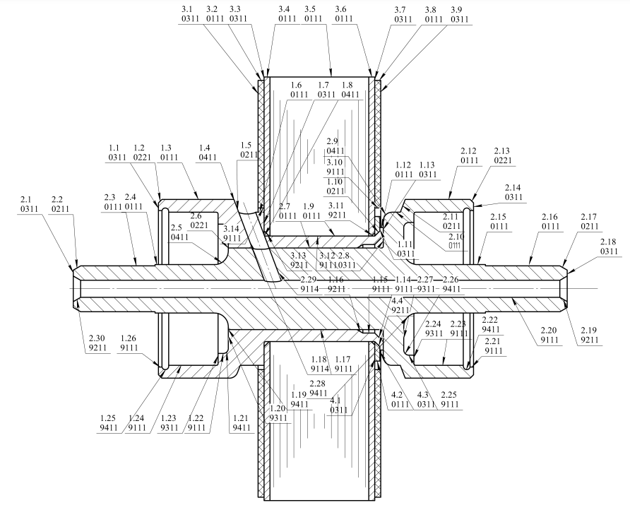
Fig. 3. Numbering of AU surfaces “Stator Package 2”
Table 1
|
No. of PAU, surfaces |
Code |
Type |
|
Part “Bushing” |
||
|
1.1 |
0311 |
Outer end |
|
1.2 |
0221 |
External chamfer |
|
1.3 |
0111 |
External cylindrical |
|
1.4 |
0411 |
Curved external |
|
1.5 |
0211 |
Outer cone |
|
1.6 |
0111 |
Outer cylindrical |
|
1.7 |
0311 |
Outer end |
|
1.8 |
0411 |
Outer curve |
|
1.9 |
0111 |
External cylindrical |
|
1.10 |
0211 |
Outer cone |
|
1.11 |
0311 |
Outer end |
|
1.12 |
0111 |
External cylindrical |
|
1.13 |
0311 |
Outer end |
|
1.14 |
9211 |
Internal cone |
|
1.15 |
9111 |
Internal cylindrical |
|
1.16 |
9211 |
Internal cone |
|
1.17 |
9111 |
Internal cylindrical |
|
1.18 |
9114 |
Cylindrical hole at an angle to the axis of rotation |
|
1.19 |
9411 |
Curvilinear internal |
|
1.20 |
9311 |
Inner end |
|
1.21 |
9411 |
Curvilinear internal |
|
1.22 |
9111 |
Internal cylindrical |
|
1.23 |
9311 |
Inner end |
|
1.24 |
9111 |
Internal cylindrical |
|
1.25 |
9411 |
Curvilinear internal |
|
1.26 |
9111 |
Internal cylindrical |
|
Part “Axle” |
||
|
2.1 |
0311 |
Outer end |
|
2.2 |
0211 |
Outer cone |
|
2.3 |
0111 |
External cylindrical |
|
2.4 |
0111 |
External cylindrical |
|
2.5 |
0411 |
Outer curve |
|
2.6 |
0221 |
External chamfer |
|
2.7 |
0111 |
External cylindrical |
|
2.8 |
0311 |
Outer end |
|
2.9 |
0411 |
Outer curve |
|
2.10 |
0111 |
External cylindrical |
|
2.11 |
0211 |
Outer cone |
|
2.12 |
0111 |
External cylindrical |
|
2.13 |
0221 |
External chamfer |
|
2.14 |
0311 |
Outer end |
|
2.15 |
0111 |
External cylindrical |
|
2.16 |
0111 |
External cylindrical |
|
2.17 |
0211 |
Outer cone |
|
2.18 |
0311 |
Outer end |
|
2.19 |
9211 |
Internal cone |
|
2.20 |
9111 |
Internal cylindrical |
|
2.21 |
9111 |
Internal cylindrical |
|
2.22 |
9411 |
Curvilinear internal |
|
2.23 |
9111 |
Internal cylindrical |
|
2.24 |
9311 |
Inner end |
|
2.25 |
9111 |
Internal cylindrical |
|
2.26 |
9411 |
Curvilinear internal |
|
2.27 |
9311 |
Inner end |
|
2.28 |
9411 |
Curvilinear internal |
|
2.29 |
9114 |
Cylindrical hole at an angle to the axis of rotation |
|
2.30 |
9211 |
Internal cone |
|
Part “Spacer” |
||
|
4.1 |
0311 |
Outer end |
|
4.2 |
0111 |
External cylindrical |
|
4.3 |
0311 |
Outer end |
|
4.4 |
9211 |
Internal cone |
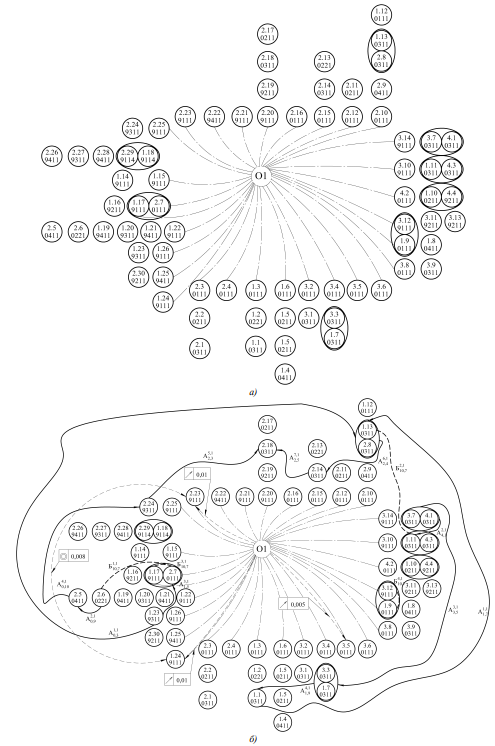
Fig. 4. Generalized graph of AU surfaces “Stator Package 2”
The next step is to establish the relationship between the assembly requirements and AU surfaces. In the presented example, the assembly requirements are evaluated, interconnected through the surface of the part “Bushing” 1.13 “Outer end” (Fig. 5).
For the qualitative distribution of critical elements into groups and the detection of those that cannot be provided by the method of complete interchangeability, it is necessary to conduct a correlation analysis of the accuracy of dimensional tolerances between the surfaces of the PAU and the specified tolerances of the shape and location of these surfaces.
The performed studies included the analysis of the interfaces of working or connecting surfaces predominantly found in the PAU of high-precision products and their correlation with shape and location tolerances (total shape and location tolerances), which are most characteristic of these combinations.
Based on the conducted research, an order was determined for the unambiguous identification of critical elements that cannot be provided by the method of complete interchangeability. As a result, specific dimensional chains and design parameters of the unique parts included in them were identified:
The performed approbation of the developed graph construction techniques and the formed rules on the example of the analysis of the requirements for the AU “Stator Package 2” under the conditions of the current multiproduct manufacture showed their operability. Identified critical assembly requirements that do not meet the conditions of complete interchangeability include:
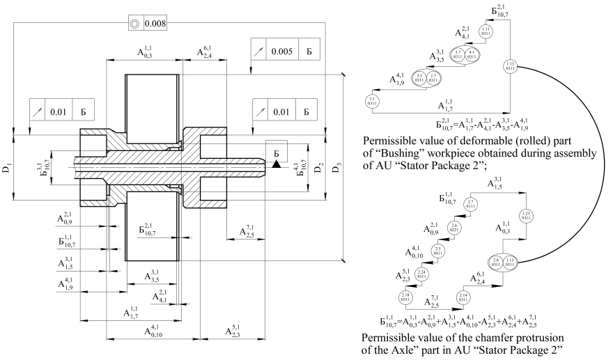
Fig. 5. Requirements for assembly of AU “Stator Package 2” with indication of surfaces between which the corresponding chain links are located
As a result of the implementation of this enlarged block of SRPPMP, initial information is formulated, including numerous assembly requirements (closing links of dimensional chains) that cannot be provided by the method of complete interchangeability. The dimensions of the PAU are the constituent links of the dimensional chains of the specified set and the set of SRPPMP to which these closing and constituent links belong. In the example under consideration, such a set will consist of “Bushing”, “Axle”, “Stator Package 1”. The dimensions of the part “Spacer” are not involved in the calculation of critical assembly requirements. At the next stages of the implementation of the SRPPMP for the received set of PAU in the SAPP, all possible options for PP are generated, and their in-process dimensional analysis is carried out. Next, the most rational options are selected from the resulting set of PP using the multicriteria optimization method. To carry out the selection procedure, a system of criteria was developed. The criterion for obtaining the maximum number of assembly kits is the basic from them. The technique of generation procedures, in-process dimensional analysis, and selection is described in detail in [6]. It should also be noted that the improvement of the methodological apparatus of the SRPPMP will allow us to proceed to the assessment of the production manufacturability of the product [11].
Discussion and Conclusion. The paper proposes the principles of constructing generalized graphs of high-precision AU surfaces and nodes, develops standards for classifying high-precision output parameters into appropriate groups and identifying critical elements of high-precision products from them. The described technique creates conditions for the complete formalization of the considered design procedure and the clarity of the graphical results of dimensional analysis. This technique makes it possible to increase the reliability of the initial information obtained during the implementation of an enlarged block of design procedures, as well as the validity and efficiency of identifying rational manufacturing methods for PAU at subsequent stages of the SRPPMP implementation, while providing the specified properties, accuracy of products, and reducing the complexity and cost of their manufacture.
The improvement of the scientific principles of the implementation of this enlarged block of design procedures of the SRPPMP increases the level of digital transformation of design and manufacturing preparation, and, along with the issues of automation of design, production and assembly, creates prerequisites for the implementation of a systematic approach to assessing the manufacturability of the products.
The next stage in the development of the proposed study is planned to supplement the generalized graph with information about the design and processing bases of the PAU, and the nature of combinations of mating connecting and working surfaces according to the classification of Professor B.M. Bazrov. The introduction of the specified information into the generalized graph will make it possible to finally form the methodological support for this enlarged block of design procedures.
1. GOST 30893.1-2002 (ISO 2768-1-89). General Tolerances. Limit Deviations for Linear and Angular Dimensions without Tolerance Indications. URL: https://files.stroyinf.ru/Data2/1/4294816/4294816276.pdf (accessed: 29.11.2023) (In Russ.).
2. GOST 8908-81. Standard Angles and Angle Tolerances. Basic Norms of Interchange Ability. URL: https://docs.cntd.ru/document/1200011833 (accessed: 29.11.2023) (In Russ.).
1. Bazrov BM. Classification of Objects of Technological Preparation in the Machining Production. IOP Conference Series: Materials Science and Engineering. 2021;1047:12048. https://doi.org/10.1088/1757-899X/1047/1/012048
2. Suslov A, Fedonin O, Petreshin D. Basic Fundamentals to Ensure and Increase Quality of Mechanical Engineering and Aerospace Products. Bulletin of Bryansk State Technical University. 2020;87(2):4–10. https://doi.org/10.30987/1999-8775-2020-2020-2-4-10
3. Osetrov VG, Slashchev ES. Assembly in Mechanical Engineering, Instrumentation. Theory, Technology and Organization. Monograph. Izhevsk: Izhevskii institut kompleksnogo priborostroeniya; 2015. 328 p. (In Russ.).
4. Peng Lin, Ming Li, Xiangtianrui Kong, Jian Chen, George Q. Huang, Meilin Wang. Synchronisation for Smart Factory — Towards IOT-Enabled Mechanisms. International Journal of Computer Integrated Manufacturing. 2017;31(7):624–635. https://doi.org/10.1080/0951192X.2017.1407445
5. Mitin SG. Synthesis of Production Operations with a Complex Structure in Multi-Nomenclature Machining Systems. Dr.Sci. (Engineering) diss. Saratov; 2017. 270 p. (In Russ.).
Alexandr V. Nazaryev, Cand.Sci. (Eng.), Head of the Design Sector
1, Osipov St., Saratov, 410019
Pyotr Yu. Bochkarev, Dr.Sci. (Eng.), Professor of the Mechanical Engineering Department, Professor of the AIC Engineering Support Department
6a, Lenin St., Kamyshin, Volgograd Region, 403805
1, Teatralnaya Sq., Saratov, 410012
Nazaryev A.V., Bochkarev P.Yu. Improving the Principles of Identifying Critical Requirements for the Assembly of High-Precision Products. Advanced Engineering Research (Rostov-on-Don). 2024;24(1):66-77. https://doi.org/10.23947/2687-1653-2024-24-1-66-77


Advanced Engineering Research (Rostov-on-Don)
ISSN 2687-1653 (Online)
Contact with: Publisher / Editorial Office of the Journal
Publisher: Don State Technical University - DSTU, Rostov-on-Don, Russia - https://donstu.ru/en/
Editor-in-Chief: Alexey N. Beskopylny, Dr.Sci. (Eng.), Professor, Vice-Rector, Don State Technical University (Rostov-on-Don, Russia)
Don State Technical University
1, Gagarin Sq., Rostov-on-Don, 344003, Russia
tel.: +7 (863) 2738-372, e-mail: vestnik@donstu.ru
16+
Processing of personal data


