


Contents
Scroll to:
https://doi.org/10.23947/2687-1653-2025-25-3-208-220
EDN: AAVODZ
Scroll to:
Introduction. Increasing the productivity of single-wire surfacing through raising the wire feed rate causes defects — undercuts and poor fusion between layers, which reduces the quality of the deposited coating and increases the reject rate. To solve this problem, multiwire surfacing techniques are being developed in a shielded gas environment which increase productivity without compromising quality. The literature shows that the relative position of electrodes in multiwire systems affects significantly the thermal and electrophysical characteristics of the arc, and therefore, the geometry of the reinforcement and the shape of the fusion penetration. However, the available studies are fragmentary: there is insufficient data on the morphology of the fusion zone, and the relationship of its parameters and specific electrode arrangement schemes under twin-arc surfacing in a shielded environment, which leaves a scientific gap. The objective of this research is to evaluate the change in the geometric parameters of the reinforcement of the deposited layer and the morphology of the fusion zone with different relative positions of the electrodes under twin-arc surfacing in a shielded gas environment.
Materials and Methods. The experiment was conducted on a 6-axis Fanuc 120iD robot with an EWM Titan XQ500 power source and an experimental surfacing head consisting of two welding torches. The layers were deposited on steel substrates of grade St3 using the GMAW Pulse method with Sv 08G2S wire with a diameter of 1.2 mm in an Ar/CO₂ environment (98%/2%) under a fixed surfacing mode (WFS = 6.5 m/min for each torch, TS = 4 mm/s, MW = 150°C). The following parameters were adopted as the studied factors: distances between electrodes (z = 15, 18, 21 mm), their angle of inclination (α = 5°, 10°). On the cross-sections of the deposited layers prepared by grinding and etching, the geometric parameters of reinforcement (height h, width S, wetting angle γ) and fusion penetration (depths a, a₁, width b) were measured. Quantitative analysis of the weld geometry was performed using Digimizer software to assess the effect of the relative position of the electrodes on the formation of the layer.
Results. It has been found that the distance between the electrodes (z) affects significantly the reinforcement geometry: a growth of z causes an increase in the layer width (S) and the wetting angle (γ), but a decrease in its height (h). The axial fusion depth (a) demonstrated a nonlinear dependence on z, reaching a maximum (~2.2 mm) at z = 18 mm. The inclination angle (α) had a minor effect (<5%)on the reinforcement parameters, but affected significantly the shape of the main fusion zone (a₁): an increase in α decreased a₁ and made the penetration more gently sloping. At z = 21 mm, the impact of α on the penetration disappeared. The relationships between the relative positions of the electrodes under twin-arc surfacing, the geometric parameters of the reinforcement, and the depth of the fusion zone were specified.
Discussion. The explanation of the established dependences is based on the change in the thermal and electrophysical properties of the electric arc depending on the mutual arrangement of the electrodes. The axial depth of fusion penetration depends not only on the distance between the electrodes, but also on the volume of the weld pool. With an excessive volume of the weld pool for a specific surfacing mode, a damping effect of heat flows from the electric arc to the base metal occurs — the volume of the weld pool absorbs part of the heat, which causes a decrease in the depth of penetration. The change in the arc pressure vector with an increase in the angle between the electrodes explains the decrease in the depth of the main fusion zone.
Conclusion. The regularities of the effect of the mutual arrangement of electrodes on the geometry of the deposited layer and the shape of the fusion zone under twin-arc surfacing in a shielded gas have been experimentally established. It is shown that an increase in the distance between the electrodes results in an increase in the width of the bead, a decrease in its height, and an increase in the wetting angle. It has been noted that the penetration depth depends on the volume of the weld pool. It is determined that the angle of inclination of the electrodes in the studied modes has an insignificant effect — less than 5% — on the geometry of the deposited metal, although hypothetically, it can be enhanced at smaller interelectrode distances. The data obtained extract clear trends and form the basis for further in-depth study of the thermal and electrophysical aspects of the process of twin-arc surfacing in a shielded gas environment.
Skoblikov I.P., Efimov E.I., Murzin V.V. Study of Effect of Electrode Arrangement on Layer Geometry and Fusion Zone Morphology under Twin-Arc Surfacing. Advanced Engineering Research (Rostov-on-Don). 2025;25(3):208-220. https://doi.org/10.23947/2687-1653-2025-25-3-208-220. EDN: AAVODZ
Introduction. The development of welding and surfacing technologies plays a key role in the automotive industry, shipbuilding, energy, and other branches of mechanical engineering, where high performance characteristics of parts are required. Gas-shielded arc surfacing and welding remain among the most common techniques for obtaining wear-resistant and corrosion-resistant surface layers. One of the tasks of modern welding production is to increase the productivity of surfacing while maintaining quality. Currently, this task is relevant in additive technologies based on GMAW, where it is often required to increase the deposition rate to reduce production times and costs [1]. This is especially urgent in the manufacture of large-sized parts in shipbuilding, aerospace, and other industries [2]. The use of multiwire deposition also allows for the control of the chemical composition of the deposited metal using filler wires with different chemical compositions [3].
Achieving greater productivity by simply increasing the wire feed speed and/or welding line speed in traditional single-wire gas-shielded welding and surfacing processes results in defects such as undercuts or humping. According to [4], undercuts are caused by high heat input, while humping is explained by the high instantaneous cooling rate of the weldpool, due to the excessive tool speed for the selected surfacing mode.
From papers [5–7] devoted to the study of defect formation in the process of high-speed welding, it follows that the maximum productivity of single-wire welding/surfacing systems in a shielding gas, providing defect-free formation, is in the region of 3–4 kg/h for steel wires. This assessment is comparable to the conclusions of paper [8], devoted to the study of multiwire welding.
The authors of [8] reviewed multiwire welding/surfacing and compared this method to traditional single-wire processes. One of the conclusions is that a significant increase in surfacing productivity is achieved not by increasing the wire feed rate or the diameter of the fed wire in a single-wire system, but by increasing the number of melted wires using a single working tool. In [2], numerous techniques of surfacing in a shielded gas environment using several consumable electrodes are distinguished. However, there is no detailed description of the surfacing system, where two electrodes are connected to one power source. It is briefly mentioned that this surfacing process is unstable, and its implementation requires systems for forced control of the surfacing mode, providing a uniform speed of wire melting. The authors of paper [9] confirm that the double-wire surfacing is not stable when working at high voltages (27–33 V): the electric arc burns alternately on each electrode with a certain frequency. However, when the voltage is reduced to 26 V, a V-shaped stable arc is formed, providing a globular transfer of metal into the weldpool. The globule is formed due to the merging of electrode metal droplets under the action of the electromagnetic field generated by the flow of electric current through the electrodes. It should be noted that the study in [9] was conducted using modified equipment for submerged arc welding and a power source providing a hard/flat volt-ampere characteristic (VAC), typical for submerged arc welding or welding in a shielded gas environment with short circuits. In [10], the authors studied the process of twin-arc welding using a pulsed surfacing mode. This mode provides stable droplet transfer of metal according to the mechanism: one drop per pulse (ODPP). To control the droplet size, the authors have proposed a technique based on the dependence of the droplet diameter on the median value of the pulse current. It is found that this adjustment is required, since the force of their mutual attraction to each other depends on the size of the droplets. When droplets of molten metal collide in the arc gap, the arc combustion is destabilized.
The arrangement of electrodes in the welding/surfacing process plays a key role that determines the form of reinforcement of the deposited metal and the fusion zone, as well as the formation of defects. Among the multiwire surfacing techniques, systems with a longitudinal or transverse arrangement of the working tool relative to the movement vector are distinguished. The process with a longitudinal arrangement of electrodes is called tandem. This arrangement of electrodes is typical for systems that perform welded joints [11]. For surfacing, a transverse arrangement of electrodes relative to the displacement vector of the working tool is typical [11].
In addition to the spatial arrangement of the electrodes, the shape of the reinforcement and the fusion zone are significantly affected by the positioning of the electrodes relative to each other. The electrodes can be spaced apart or brought together at a certain distance or tilted relative to each other [11]. The distance between the electrodes during twin-arc surfacing has a significant effect on the pressure of the electric arc and the heat distribution in it. The authors [11] performed numerical simulation of the thermal fields of an electric twin-arc without a gap and with a gap of 1 mm between the electrodes. In this case, the electrodes were located in parallel. When surfacing with a gap, a decrease in the electric arc pressure of 1.3 times was calculated, and compared to single-wire surfacing — by 4.2 times. According to the experiments conducted in this work, it was determined that when surfacing with a gap, the penetration depth decreased, and the width of the deposited metal increased.
Based on the above, it follows that twin-arc surfacing in a shielded gas is of interest to heavy industry, including those using additive methods of electric arc deposition. This process is capable of providing stable burning of an electric arc when using pulsed surfacing modes, but requires detailed adjustment of current pulses for metal transfer in the ODPP mode. The use of two wires in one welding head allows for a significant reduction in electric arc pressure compared to traditional single-wire welding systems. When the electrodes are moved apart from each other, the electric arc pressure decreases, which changes the shape of the reinforcement and the penetration zone.
Based on the analysis, it has been revealed that there is no comprehensive study of the effect of the relative position of electrodes under multiwire twin-arc surfacing in a shielded gas environment on:
The research objective is to systematically evaluate the effect of the working tool configuration on the geometric parameters of the reinforcement and the shape of the fusion under twin-arc surfacing in a shielded gas environment. To perform this study, a designed surfacing head was used, consisting of two welding torches fixed on a bracket that allowed them to adjust their relative position to each other. The analysis of the geometric parameters of the reinforcement shape and the fusion zone was performed on macrosections.
The following tasks were set within the framework of the objective:
Materials and Methods. A 6-axis Fanuc 120iD robot was used in conjunction with an EWM Titan XQ500 power source to conduct the research. The working tool was an experimental surfacing head consisting of two welding torches mounted on an adjustable bracket. A ruler and a digital level were used to adjust the relative position of the welding torches. Figure 1 shows a photo and an installation diagram.
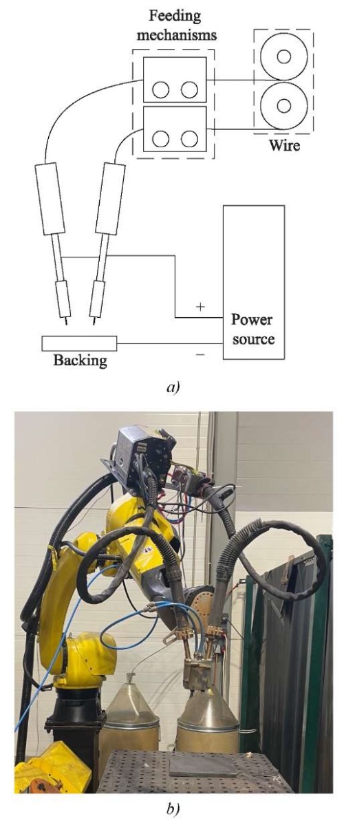
Fig. 1. Laboratory setup:
a — laboratory setup diagram; b — photo of the laboratory setup
The substrates were made of St3 steel sheets with dimensions of 150×70×20 mm. Surfacing was performed by the GMAW-Pulse method using Sv-08G2S welding wire with a diameter of 1.2 mm. The chemical composition of the wire is given in Table 1. A mixture of argon (98%) and carbon dioxide (2%) was used as a shielded gas environment. The temperature of the substrate preheating was controlled using a HIKMICRO B20 thermal imager. To visualize the macrostructure of the deposited layer and the heat-affected zone, samples were etched by an electrolytic method in a concentrated solution of sodium chloride (NaCl). The results were analyzed using Digimizer software.
Table 1
Chemical Composition of Wire Sv-08G2S (wt.%)
|
C |
Si |
Mn |
P |
S |
Ni |
Cr |
Cu |
|
0.05–0.11 |
0.70–0.95 |
1.80–1.90 |
≤ 0.030 |
≤ 0.025 |
≤ 0.025 |
≤ 0.020 |
≤ 0.025 |
The following parameters were selected as independent factors to determine the relative position of the torches: the distance between the electrodes (z) and their angle of inclination relative to the vertical (α). The surfacing was performed with the same extension (SO) equal to 20 mm. Figure 2 shows a schematic representation of the described parameters.
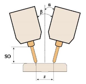
Fig. 2. Parameters under study
The layers were deposited with a wire feed rate (WFS) of 6.5 m/min on each torch and a constant linear speed (TS) of 4 mm/sec. Current (I) and voltage (U) were recorded during deposition. Substrates with identical overall dimensions were used to maintain a similar thermal pattern. Before depositing the layer, the substrates were cleaned to a metallic shine and heated to a temperature (MBT) of 150°C. Heating was performed with a gas torch. The shielded gas flow rate for each torch was 15 l/min. Table 2 shows the deposition mode values.
Table 2
Surfacing Mode
|
WFS, m/min |
I, А |
U, В |
TS, mm/s |
МВТ, °С |
SO, mm |
Gas consumption, l/min |
|
6.5 |
420 |
25 |
4 |
150 |
20 |
15 |
The determination of the limiting values of the factors was carried out on account of the design features of the working tool and the conditions for the formation of the deposited metal. The minimum value α, that could be set for the working tool was 5°, and the maximum was 10°. The minimum value of parameter Z, equal to 15 mm, was also determined by the design of the surfacing head. The maximum value of parameter Z was taken to be equal to 21 mm, since with a larger distance between the electrodes under the same surfacing mode it was not possible to obtain a continuous layer. To assess the effect of the selected factors, it was decided to conduct two single-factor experiments, where the grouping value was the angle of inclination of the electrodes. Table 3 shows the experimental plan taking into account the boundary conditions.
Table 3
Test Plan
|
Experiment |
z, mm |
α, ° |
|
1 |
15 |
5 |
|
2 |
18 |
5 |
|
3 |
21 |
5 |
|
4 |
15 |
10 |
|
5 |
18 |
10 |
|
6 |
21 |
10 |
Sampling was carried out on a section equal to 3/4 of the length of the deposited layer. It was assumed that on this section of the layer the thermal picture during deposition of the layer was identical. Figure 3 shows a photograph of the selection of samples for the study.
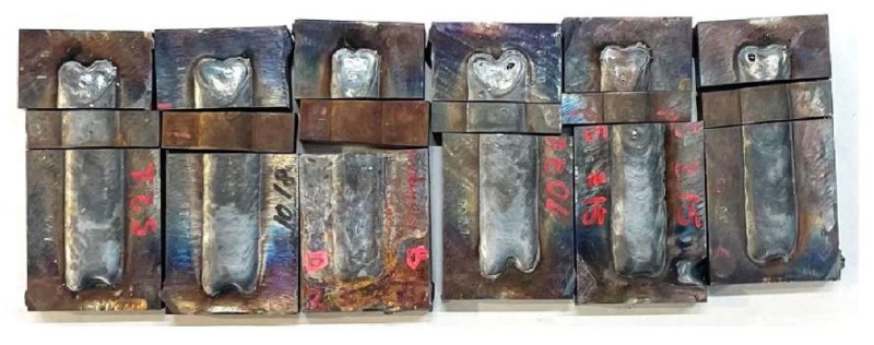
Fig. 3. Sampling
After cutting out the samples, grinding and etching of the cross-sections of the deposited layers were performed. Figure 4 shows the macrostructure of the cross-sections of the deposited layers.
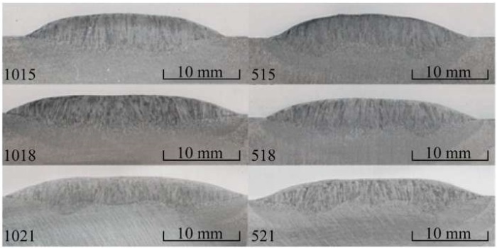
Fig. 4. Photo of the macrostructure of the deposited metal
To quantify the impact of the relative position of the electrodes on the formation of the layer, the Digimizer program outlined and measured the areas of the layer cross-section that characterized the reinforcement and the fusion zone. The following geometric parameters of the bead were selected as a response to the variable factors: layer height (h), layer width (S), bead wetting angle (ɣ).
Analyzing the fusion shape of each deposited layer, several zones with similar geometric characteristics can be identified. The first zone (P1), characteristic of all deposition modes, is located on the layer axis. The second zone (P2) occurs on both sides of the axial zone and is called the main zone. Figure 5 shows a schematic representation of the fusion zones under study.
Depending on the relative position of the electrodes, the shape of the fusion changes — it changes its depth (a or a1) and width (b). Figure 6 shows a schematic representation of the specified parameters.
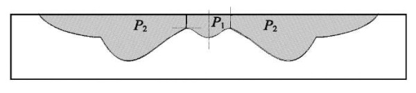
Fig. 5. Fusion zones
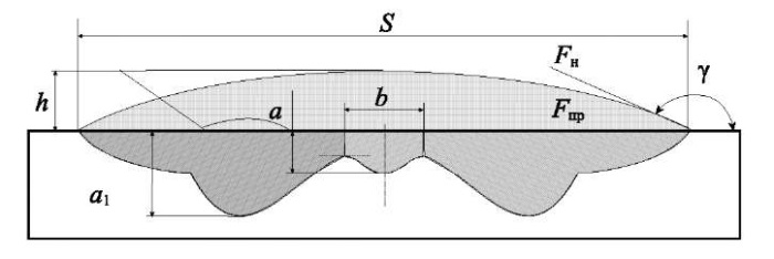
Fig. 6. Layer cross-section shape diagram
Research Results. Figure 7 shows photographs of the macrostructure of the deposited metal with reference points applied to them for measuring the shape of the deposited layer and the fusion zone in the Digimizer program. Figure 8 shows graphs reflecting the geometric parameters of the reinforcement and the fusion zone for each deposited layer. The measurements are performed in the Digimizer program. The graphs are grouped according to the criterion of the angle of inclination of the electrodes relative to the vertical.
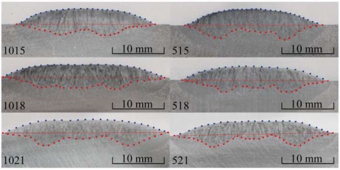
Fig. 7. Determination of boundaries of geometric parameters of reinforcement and fusion zone
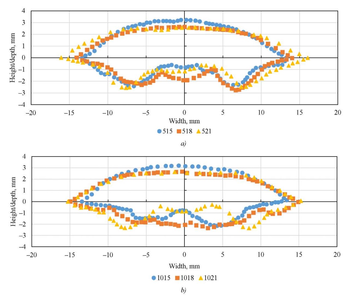
Fig. 8. Geometric parameters of reinforcement and fusion shape:
a — at α = 5° for z = 15, 18, 21 mm; b — at α = 10° for z = 15, 18, 21 mm
Based on the data obtained, graphs were constructed to assess the magnitude and nature of the responses under study. Figures 9–11 show graphs describing the change in the geometric characteristics of the gain depending on the relative position of the electrodes. Figures 12–13 show graphs illustrating how the width and depth of fusion on the layer axis and the depth of penetration in the main zone change when the relative position of the electrodes changes.
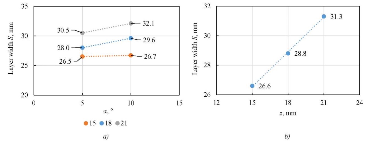
Fig. 9. Change in gain width from relative position of electrodes:
a — dependence of layer width on angle of inclination of electrodes α;
b — dependence of layer width on distance between electrodes z
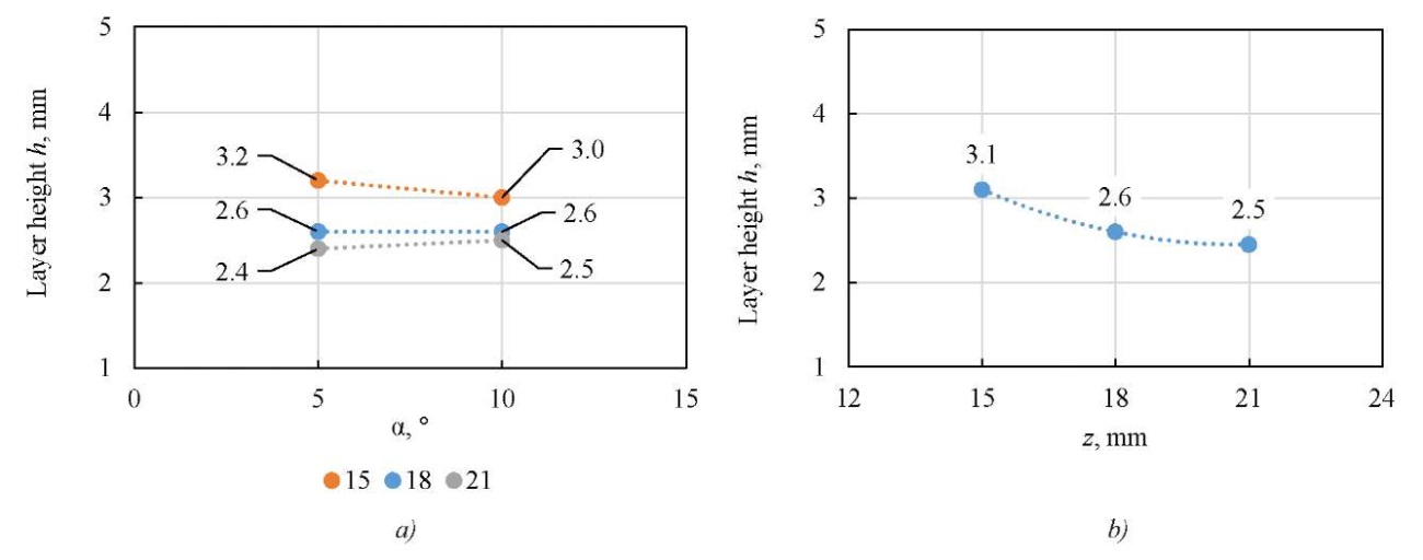
Fig. 10. Change in height of gain of relative position of electrodes:
a — dependence of layer height on angle of inclination of electrodes α;
b — dependence of layer height on distance between electrodes z
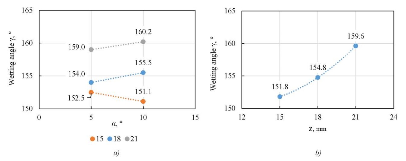
Fig. 11. Dependence of wetting angle of gain on relative position of electrodes:
a — dependence of wetting angle of gain on angle of inclination of electrodes α;
b — dependence of wetting angle of gain on distance between electrodes z
The results of the measurements show that the width, height and wetting angle of the deposited layer depend on the distance between the electrodes. As the distance between the electrodes grows, the width of the layer increases, its height decreases, and the wetting angle becomes larger.
The impact of the angle between the burners on the roller geometry is determined to be insignificant. When changing the angle of inclination between the burners, the studied geometric characteristics of the reinforcement change by an amount not exceeding 5%.
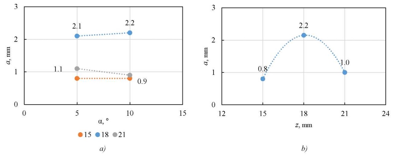

Fig. 12. Depth and width of fusion in different zones:
a — dependence of axial fusion depth on electrode inclination angle α;
b — dependence of axial fusion depth on distance between electrodes z;
c — dependence of main fusion depth on electrode inclination angle α;
d — width of axial fusion depth depending on electrode inclination angle α
It follows from the measurement results that with relatively close electrode position, the change in the axial fusion depth is insignificant. The main effect on the axial depth is exerted by the distance between the electrodes.
The change in the width of the axial fusion zone is determined by the angle of the electrodes: with a growth in the angle between the electrodes, the width of the axial zone increases. The depth of fusion penetration in the main zone also depends on the angle between the electrodes — with an increase in the angle, the depth of axial fusion decreases. However, with a relatively large distance between the electrodes, the effect of the angle on the change in the width and depth of individual fusion zones is absent. The dependence of the cross-sectional area of the melted metal on the relative position of the electrodes has not been established.
Discussion. Dependences have been identified that confirm the effect of the angle and distance between the electrodes on the shape of the fusion and the geometric parameters of the deposited layer.
The change in the geometry of the deposited layer depending on the distance between the electrodes occurs due to the different distribution of the mass of molten metal over the deposited surface. When the heat sources are separated, a weldpool with a different mirror area is formed. As a result, with an increase in the distance between the electrodes, the deposited layers become wider, the layer height – smaller, and the wetting angle increases.
Changing the angle of inclination of the electrodes relative to the vertical plane with a constant distance between the electrodes does not have a significant effect on the geometric parameters of the deposited layer. The lack of significant effect on the shape of the reinforcement is explained by the fact that the angle of inclination determines the vector of the electric arc pressure and the force of interaction of electromagnetic fields, but does not determine the area of the weldpool mirror. These results agree with theoretical expectations.
Based on the analysis of the data on the shape of the fusion, it follows that both factors — the angle of inclination of the electrodes and the distance between them — are significant. This is explained by the fact that these parameters affect the interaction of electromagnetic fields that arise when electric current flows through the electrodes. This interaction, in turn, affects the distribution of heat in the electric arc and its pressure on the weldpool mirror.
When unidirectional electric current flows through conductors, an electromagnetic vacuum is created in the space between them. For this reason, a concentration of charged particles occurs in the interelectrode space. The effect of convergence of electric arcs under surfacing and the rush of plasma flows into the space between the electrodes is observed. This interaction is mentioned in [11–13]. Figure 13 shows an image of the combustion process of electric arcs, taken during the experiment.
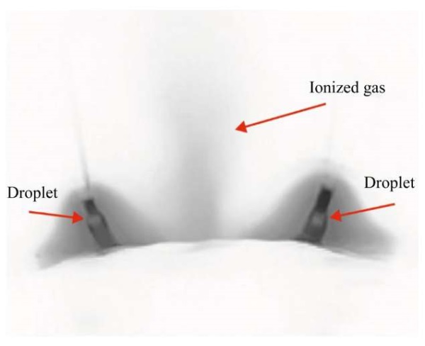
Fig. 13. Image of droplet transfer during surfacing of a layer with parameters: Z = 18 mm; α = 10°
Due to the plasma cloud between the electrodes, an axial fusion zone is formed. As the distance between the electrodes increases, the intensity of the interaction of the electromagnetic fields decreases, and the fusion penetration depth in the axial zone also decreases. With a distance between the electrodes of 18 mm and 21 mm, the axial fusion depth is 2.2 mm and 1 mm, respectively. However, with a relatively small distance between the electrodes (15 mm), the fusion depth in the axial zone is 0.9 mm. Based on the results obtained in [11], it follows that with a decrease in the distance between the electrodes, the electric arc pressure and the concentration of ionized gas in the area between the electrodes increase. Consequently, the value of the axial fusion depth should increase — which does not correspond to the data obtained.
This discrepancy is probably due to the fact that with a distance between the electrodes equal to 15 mm, a weldpool with a smaller mirror is formed during surfacing than when surfacing with a distance of 18 mm. This fact is confirmed by the smaller layer width obtained during the experiment. A weldpool with a relatively smaller mirror area, but the same volume of molten metal, has a greater thickness. Therefore, it can be concluded that a thicker layer of liquid metal prevents heat transfer from the plasma cloud and molten metal droplets to the base metal. As a result, the axial fusion depth in this experiment does not correspond to the theoretical expectation.
The effect of the angle of inclination of the electrode relative to the vertical plane on the depth of the axial fusion zone has not been determined. Most likely, the absence of this effect is explained by the significant distance between the electrodes. When the electrodes are brought closer together, the intensity of the interaction of electromagnetic fields will increase — and this factor will begin to have weight when assessing the axial fusion depth. To confirm this hypothesis, additional research is required.
In turn, the main depth of fusion penetration changes its values slightly with a change in the angle of inclination of the electrodes due to a change in the interaction of electromagnetic fields and a change in the pressure vector of the electric arc. With an increase in the inclination of the electrodes relative to each other, the vector of the pressure force of the electric arc is not perpendicular to the surface, but tends to the axis of the deposited layer. Taking into account the mutual attraction of the electric arcs, the main fusion zone has a flat, rather than pointed shape — as in surfacing with parallel torches to the vertical plane [13].
Conclusion. Thus, the following can be noted: surfacing using a twin-arc in a shielded gas environment is of interest to industry, in particular for high-performance surfacing and electric arc additive manufacturing technology. According to the literature review, this process has not been fully disclosed in terms of the interaction of electromagnetic fields, the distribution of the thermal field in an electric arc, as well as the morphology of the micro- and macrostructure of the deposited metal depending on the relative position of the electrodes under twin-arc surfacing.
As for the work done, the data obtained are insufficient to build a mathematical model that makes it possible to predetermine the geometric parameters of the deposited layer and the fusion shape, but they are sufficient to form an idea of the trends and patterns in the deposited and molten metal under twin-arc surfacing in a shielded gas environment with different mutual arrangements of the electrodes.
The following dependences are defined:
This study serves as a starting point for further research of the thermophysical and electrophysical properties of an electric twin-arc in a shielded gas environment depending on the relative position of the electrodes.
1. Somashekara MA, Suryakumar S. Studies on Dissimilar Twin-Wire Weld-Deposition for Additive Manufacturing Applications. Transactions of the Indian Institute of Metals. 2017;70:2123–2135. https://doi.org/10.1007/S12666-016-1032-3
2. Rui Xiang, Jiankang Huang, Xiaoquan Yu, Huayu Zhao, Ding Fan. A Review of Double-Electrode GMAW: Approaches, Developments and Variants. Journal of Manufacturing Processes. 2025;133:1160–1182. https://doi.org/10.1016/j.jmapro.2024.12.017
3. Sudnik W. Physical Mechanisms and Mathematical Models of Bead Defects Formation During Arc Welding. In book: Arc Welding. London: InTech; 2011. P. 243–266. https://doi.org/10.5772/30803
4. Zong R, Chen J, Chen MA. Undercutting Formation Mechanism in Gas Metal Arc Welding. Welding Journal. 2016;95:174–184.
5. Lin Wang, Ji Chen, Juansong Wu, Jinqiang Gao. Backward Flowing Molten Metal in Weld Pool and Its Influence on Humping Bead in High-Speed GMAW. Journal of Materials Processing Technology. 2016;237:342–350. https://doi.org/10.1016/j.jmatprotec.2016.06.028
6. Bajcer B, Hrženjak M, Pompe K, Jež B. Improvement of Energy and Materials Efficiencies by Introducing Multiple-Wire Welding. Metalurgija. 2007;46(1):47–52.
7. Siyuan Han, Guoqiang Liu, Xinhua Tang, Lidong Xu, Haichao Cui, Chendong Shao. Effect of Molten Pool Behaviors on Welding Defects in Tandem NG-GMAW Based on CFD Simulation. International Journal of Heat and Mass Transfer. 2022;195:123165. https://doi.org/10.1016/j.ijheatmasstransfer.2022.123165
8. Elsukov SK, Sokolov GN, Zorin IV, Fastov SA, Polunin IA. Investigation of the Arc Process of a Split Electrode in a Gas Metal Arc Welding. Izvestia VSTU. 2020;237(2):62–66. https://doi.org/10.35211/1990-5297-2020-2-237-62-66
9. Kaiyuan Wu, Jiatong Zhan, Xuanwei Cao, Min Zeng, Nian Ding. Metal Transfer of Aluminum Alloy Double-Wire Pulsed GMAW with a Median Waveform. Journal of Materials Processing Technology. 2020;286:116761. https://doi.org/10.1016/j.jmatprotec.2020.116761
10. Guoqiang Liu, Siyuan Han, Xinhua Tang, Haichao Cui. Effects of Torch Configuration on Arc Interaction Behaviors and Weld Defect Formation Mechanism in Tandem Pulsed GMAW. Journal of Manufacturing Processes. 2021;62:729–742. https://doi.org/10.1016/j.jmapro.2021.01.007
11. Xiaoli Wang, Yangsen Liu, Qi Zhang, Chengfu Luo, Qingxian Hu. Numerical Analysis Arc Behavior in SinglePower Double-Wire Single-Arc Gas Metal Arc Welding. Results in Engineering. 2025;26:105538. https://doi.org/10.1016/j.rineng.2025.105538
12. Ning Xiao, Haoyu Kong, Qingjie Sun, Ninshu Ma. Study of Process, Microstructure, and Properties of Double-Wire Narrow-Gap Gas Metal Arc Welding Low-Alloy Steel. Materials. 2024;17(24):6183. https://doi.org/10.3390/ma17246183
13. Kaiyuan Wu, Yifei Wang, Taoyuan Tao, Xiaobin Hong. Effect of Phase Shift on Arc Interference and Weld Bead Formation in Aluminum Alloy Tandem GMAW with a Median Pulsed Waveform. The International Journal of Advanced Manufacturing Technology. 2022;120:8013–8030. https://doi.org/10.1007/s00170-022-09200-5.
Iakov P. Skoblikov, Postgraduate student of the Department of Welding of Ship Structures
3, Lotsmanskaya, Saint Petersburg, 190121
ScopusID 57289868500
Evgeny I. Efimov, Head of the Engineering Center
24B, Central Office, Sverdlovskoye Town, Vsevolozhsk District, Leningrad Region, 188400
Viktor V. Murzin, Cand.Sci. (Eng.), Associate Professor of the Department of Welding of Ship Structures
3, Lotsmanskaya, Saint Petersburg, 190121
An experimental approach is developed to assess the effect of electrode spacing on the shape and geometry of the deposited layer using a twin-arc. It is shown that increasing the spacing between electrodes widens the bead, reduces its height, and increases the wetting angle. It is established that the axial fusion depth depends on the surface area of the weldpool and does not vary monotonically with the spacing between electrodes. The results help optimize multi-wire welding parameters to improve productivity while maintaining quality.
Skoblikov I.P., Efimov E.I., Murzin V.V. Study of Effect of Electrode Arrangement on Layer Geometry and Fusion Zone Morphology under Twin-Arc Surfacing. Advanced Engineering Research (Rostov-on-Don). 2025;25(3):208-220. https://doi.org/10.23947/2687-1653-2025-25-3-208-220. EDN: AAVODZ


Advanced Engineering Research (Rostov-on-Don)
ISSN 2687-1653 (Online)
Contact with: Publisher / Editorial Office of the Journal
Publisher: Don State Technical University - DSTU, Rostov-on-Don, Russia - https://donstu.ru/en/
Editor-in-Chief: Alexey N. Beskopylny, Dr.Sci. (Eng.), Professor, Vice-Rector, Don State Technical University (Rostov-on-Don, Russia)
Don State Technical University
1, Gagarin Sq., Rostov-on-Don, 344003, Russia
tel.: +7 (863) 2738-372, e-mail: vestnik@donstu.ru
16+
Processing of personal data


