


Contents
Scroll to:
https://doi.org/10.23947/2687-1653-2022-22-1-30-41
Scroll to:
Introduction. The launch vehicle (LV) in flight and the dynamic components of loads from the impact of a trapezoidal wind gust are considered. It is proposed to determine the dynamic components of the force factors using analytical solutions for the structure points accelerations. The work objective is to create a technique for selecting the duration of the standard gust, under the influence of which maximum loads are provided in the sections of the LV structure.
Materials and Methods. The launch vehicle is presented as an uneven beam. The description of its vibrations is reduced to a system of independent ordinary differential equations that determine the motion of an equivalent system of oscillators. The equation of oscillator vibrations under the action of a trapezoidal pulse load is solved by the overlay method, and it is reduced to the calculation of the Duhamel integral. It is proposed to get the parameters of an equivalent system of oscillators based on the results of the calculation of dynamic characteristics for a finite element LV model in the Nastran program.
Results. Analytical relations for the LV structure point accelerations under the action of a trapezoidal wind gust are given. For the beam model, test calculations of accelerations were carried out according to the technique proposed in this paper. These data are compared to the results of finite element modeling. With the help of analytical solutions, dependences are constructed that determine the nature of the change in the magnitude of the bending moment for different sections of the launch vehicle when the duration of the wind gust varies.
Discussion and Conclusions. The presented technique provides building an equivalent dynamic model of systems with a large number of degrees of freedom on the example of a LV and obtaining analytical solutions for accelerations of points of a mechanical system under trapezoidal external action. These solutions are applicable for the study of dynamic loads. The analysis results enable to select the duration of the wind gust, at which maximum loads are reached in the sections of the LV structure. Calculations based on the analytical solutions are very economical in terms of time spent. They can be used in design calculations for preliminary assessment of loading.
Malykhina O.I. Analytical solution to approximate equations of the launch vehicle motion under the gust action for the dynamic loading calculation. Advanced Engineering Research (Rostov-on-Don). 2022;22(1):30-41. https://doi.org/10.23947/2687-1653-2022-22-1-30-41
Introduction. During the operation of the launch vehicle (LV), loads occur in the elements of its design. We are talking about longitudinal and shear forces, bending and torsion moments. Data on these force factors are used for strength analysis in the design of new products, experimental development of the design [1], and adaptation of launch vehicles for a specific start-up [2]. Loads are divided into quasi-static and dynamic. The quasi-static ones arising in flight are calculated from the condition of dynamic equilibrium of the LV as a solid body, taking into account the permissible parameters of the ascent trajectory.
Generalized beam models are usually used to calculate dynamic loads. Such loads are determined by the results of solving the equation of the elastic LV motion, which in general is a partial differential equation. Methods based on the application of decomposition of the solution by the eigenvibration tones of the structure are able to provide a high speed of calculation in combination with sufficient accuracy of the results [3]. As shown in [4], using the method of decomposition by the forms of natural oscillations, it is possible to proceed to a system of independent ordinary differential equations. They describe:
The transition to independent equations describing elastic modes of the LV means that the distributed parameters of oscillators will be taken into account, each of which is a single-degree-of-freedom system. The motion of such an oscillator can be considered independently of the others, and a solution can be obtained for each of them using well-known methods of oscillation theory.
To calculate the loads in flight, not the entire ascent trajectory is considered, but only some of its points, the socalled load cases, characterized by the extreme value of individual parameters affecting loading, or the maximum value of loads on individual structural elements. One of the most important cases of loading is the atmospheric flight of the LV [1][5]. The influence of a turbulent atmosphere on the LV loading can be determined by statistical methods [6][7], or within the framework of a conservative approach, when the maximum possible (with some level of probability) wind characteristics are taken into account. This paper discusses the second approach. A single specified wind gust is accepted as an external dynamic effect. The profile of the specified gust, which characterizes the change in wind speed over time, can be set in a trapezoidal [8], cosine, or sinusoidal form [9]. In this paper, we will consider the launch vehicle motion under the trapezoidal gust action. The duration of the specified gust is usually selected to be comparable with the period of the lowest transverse tone of the LV1 vibrations. At the same time, there are often demands for its variation to achieve maximum efforts in the LV sections [8][10]. The complexity of calculations using standard finite element (FE) analysis programs is due to:
This paper objective is to develop a methodology for selecting the duration of the specified gust using analytical solutions obtained for a simplified dynamic LV model presented as an equivalent system of oscillators.
A semi-analytical approach using the Duhamel integral was successfully applied in [11] for hydroelastic analysis of ships. In [12] and a number of other works, the Duhamel integral is used as part of the problem solution of loading bridges with moving loads. In this paper, the Duhamel integral is used for analytical solutions to the LV reaction to the short-term impact of a wind gust in flight.
Materials and Methods. At the stages of preliminary design, it is advisable to use flat design schemes for beam models. With the simplicity and speed of the solution, they enable to determine the motion variables and internal forces (with an accuracy acceptable for this stage of design) [13]. Imagine the LV in the form of an elastic beam with variable length mass and stiffness. Assume the usual assumptions for the resistance of materials, including the hypothesis for the smallness of elastic deformations. To determine the internal force factors in the LV section, we use the acceleration (overload) method [1][4], which can be interpreted as a cross-section method adapted for dynamic calculation. In this case, internal forces are found from the conditions of static equilibrium of mentally cut off parts of the structure under the action of external distributed loads, supplemented by D'Alembert’s forces of inertia, and the desired internal forces. Quasi-static and dynamic values of force factors are determined separately based on precalculated accelerations, and then summed up [4].
This paper considers the issue of determining the dynamic loading of the LV in the transverse direction under the action of a wind gust, whose speed is directed perpendicular to the longitudinal axis of the LV. It is assumed that the loading in the longitudinal direction can be calculated independently. It is not considered in this paper.
To determine dynamic accelerations, the LV is presented as a free elastic beam. Its motion is studied in the vicinity of the moment of time corresponding to the load case under consideration, and is described in deviations from the state of dynamic equilibrium in which the LV was before the wind gust, moving along the nominal (undisturbed) trajectory. Here, such parameters as the mass and moment of inertia of the LV, the motor power, and the angle of projection are assumed to be constant and equal to the characteristics of the considered point of the nominal trajectory. The perturbed motion of the elastic LV is investigated in a fixed coordinate system associated with the position that the LV occupied at the time of the calculation. The perturbed motion will be a combination of plane-parallel motion of the LV as a rigid body in the plane in which the dynamic load is applied, and elastic modes of the structure. We do not take into account the control system response, i.e., for the stabilization machine, we assume a long delay time compared to the time of application of the dynamic load. In general, under the influence of a wind gust, together with elastic modes of the body, the LV starts to move as a rigid body. The transverse component of the aerodynamic force, which is considered proportional to it at a small angle of attack, changes its value due to the displacement of the structure in the direction of the wind gust and rotation relative to the forward flow vector. The projection of gravity on the transverse axis of the LV also changes. To properly account for these changes, the equations of LV motion must be integrated with the equations describing the logic of the automatic stabilization, which is impossible at the early stages of design. Taking into account the significant mass and the moment of inertia of the LV, we will consider small:
This enables to ignore the impact of the above changes. The angle-of-attack increment (and, consequently, the transverse component of the aerodynamic force) is considered to depend only on the magnitude of the wind gust speed given as a function of time. Thus, taking into account the accepted assumptions, the aerodynamic load in the transverse direction is a load distributed along the length of the beam with a time-dependent proportionality coefficient. The law of distribution of aerodynamic load along the length of the LV is determined experimentally and is considered to be known in advance. The law of change of the proportionality coefficient (angle of attack) from time to time is determined by the selection of the profile of the specified wind gust.
The motion of the LV modeled as an elastic beam can be described using the well-known equation of forced transverse vibrations of the beam, written with the account for Voigt's hypothesis:
 (1)
(1)
where 𝑚(𝑥) — mass per unit length; 𝐵(𝑥) — bending stiffness; 𝑞(𝑥, 𝑡) — distributed external load; ℎ — friction factor.
This equation should be supplemented with a boundary condition: the internal forces in the initial and final sections are zero. It means:
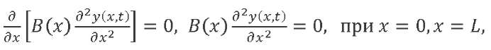 (2)
(2)
where 𝐿 — the LV length.
In this paper, the aerodynamic force is taken as an external distributed load, which can be presented as a product of functions:
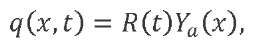 (3)
(3)
where 𝑅(𝑡) — the function that determines the temporal variability of the aerodynamic force and varies according to the trapezoidal law in accordance with the wind gust model adopted in this paper; 𝑌𝑎(𝑥) — the function of the aerodynamic force distribution along the LV length.
Let us consider free LV vibrations without taking into account friction forces (at 𝑞(𝑥, 𝑡) = 0, ℎ = 0). We substitute the variable separation method 𝑦(𝑥, 𝑡) = 𝑓(𝑥) ∙ 𝑞(𝑡). In this case, from equation (1) with boundary conditions (2), it is possible to arrive at an ordinary differential equation
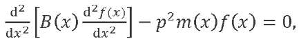 (4)
(4)
with boundary conditions:
 (5)
(5)
Solution (4) with conditions (5) is a classical Sturm-Liouville problem. Solving it, one can find a set of eigenforms 𝑓𝑗(𝑥) and eigenfrequencies 𝑝𝑗 of the beam in question (𝑗 = 1, 2, … ). It is known2 that some solutions to system (4) correspond to zero natural frequencies. The forms corresponding to zero natural frequencies determine the translational motion of the LV as a rigid body together with the center of mass and rotation around the center of mass: 𝑓−1 = 1, 𝑓0 = 𝑥 − 𝑥𝐶, where 𝑥𝐶 — coordinate of the LV center of mass.
It should be noted that the LV mass and stiffness characteristics most often have a piecewise constant pattern of distribution. In this case, the equations of form (1) and (4) should be written separately for each homogeneous beam section with boundary conditions at the junctions of the sections, as in the derivation of the ratios of the initial parameters method [1][14]. In the given paper, this entry is omitted, because the calculation of the dynamic characteristics (modal analysis) of structures is carried out numerically, using the finite element method.
Let us imagine the forced vibrations of an elastic beam modeling the LV structure in the form of decomposition according to the natural modes. Assume that the beam stiffness axis passes through its center of mass. To move the points of the LV axis, we write:
 (6)
(6)
where 𝑦𝐶 (𝑡) — displacement of the beam center of mass; ϑ(𝑡) — angle of rotation of the axis of the undeformed beam; 𝑓𝑗 — beam eigenmode corresponding to tone numbered 𝑗; 𝑞𝑗(𝑡) — generalized coordinate corresponding to tone numbered 𝑗; 𝑁 — number of elastic tones taken into account.
After substituting (6) into (1) and applying the Bubnov-Galerkin procedure, we can arrive at an ordinary differential system with constant coefficients:
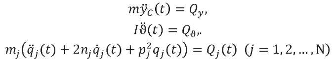 (7)
(7)
Here, 𝑚 — LV mass; 𝐼 — moment of inertia relative to the axis passing through the LV center of mass perpendicular to the plane of rotation; 𝑚𝑗 — reduced (generalized) mass for the 𝑗-th vibration tone and determined from the formula:
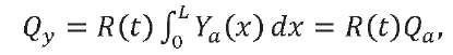
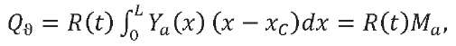
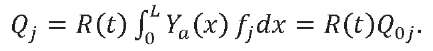
The generalized forces in expression (7), taking into account (3), are defined as follows:
 (8)
(8)
 (9)
(9)
 (10)
(10)
Here, 𝑄𝑎 — maximum value of the main transverse aerodynamic load vector; 𝑀𝑎 — maximum value of the main transverse aerodynamic moment reduced to the LV center of mass; 𝑄0𝑗 — maximum value of the generalized force corresponding to the generalized coordinate 𝑞𝑗.
The first two equations in (7) define the law of change of accelerations of the LV points in the process of translational and rotational motion of the LV as a rigid body. The last equation in (7) defines the law of motion of an equivalent system of oscillators.
Consider the motion of one oscillator under the action of a trapezoidal external load, which:
For convenience, we omit the indices characterizing the tone number. Then we will rewrite the differential equation of the oscillator motion taking into account (10) in the form:
 (11)
(11)
where 𝑚 — oscillator mass; 𝑝 — angular frequency of natural oscillations, expressed in radians per second; n — damping coefficient (determines the oscillator damping); 𝑄(𝑡) = 𝑄0𝑅(𝑡) — law of variation of external load.
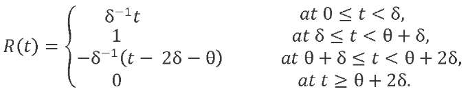
We represent function 𝑅𝑅(𝑡𝑡) as a set of four linear functions:
Accordingly, external load 𝑄(𝑡) is a combination of four linear loads 𝑄𝑖(𝑡) = 𝑄0𝑅𝑖(𝑡), (𝑖 = 1, 2, 3, 4). Load 𝑄1(𝑡) is applied from moment 𝑡 = 0; 𝑄2(𝑡) — from moment 𝑡 = δ; 𝑄3(𝑡) — from moment 𝑡 = θ + δ; 𝑄4(𝑡) — from moment 𝑡 = θ + 2δ.
To determine the system response to external actions, we divide the entire duration of the load into four intervals (Fig. 1).
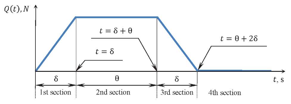
Fig. 1. Diagram of the external trapezoidal load
In accordance with the superimposition method3, let us represent the response of the linear system under consideration to an external action in the form of the Duhamel’s integral as the sum of responses to a set of independently applied elementary impulses:
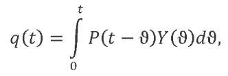
Here, 𝑃(𝑡 − ϑ) — the shifted time law of variation of external action, and 𝑌(ϑ) characterizes the system response to a unit impulse input. The response of mechanical system 𝑞𝑙(𝑡) to a linearly increasing load 𝑃(𝑡) = 𝑘𝑡 can be expressed through the system response to unit impulse 𝑌(ϑ) and to a suddenly applied single load 𝑌1(ϑ):
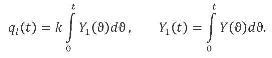
The response of a one-degree-of-freedom mechanical system with damping coefficient 𝑛 to a unit pulse will have the form4:
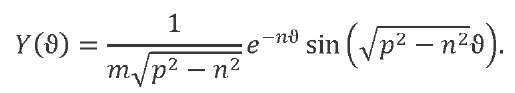
We introduce a notation for the frequency of damped vibrations ![]() . Let us calculate the system response to a suddenly applied unit load:
. Let us calculate the system response to a suddenly applied unit load:
The response to a linearly increasing load:
 (12)
(12)
We accept the notations: Δ1= 𝑡 − δ, Δ2= Δ1 − θ, Δ3= Δ2 − δ.
We introduce a function containing the harmonic terms of solution (12):
We denote by 𝑞ст the motion under the action of a force statically applied to the system 𝑄0 = 𝑞ст𝑚𝑝2 and take into account that 𝑘 = 𝑄0/δ. The total movement of the oscillator under the action of a combination of loads 𝑄𝑖 (𝑡) at every time point will be the sum of the corresponding solutions (12). The system response described by equation (11) to the external impact of the trapezoidal profile will have the form:
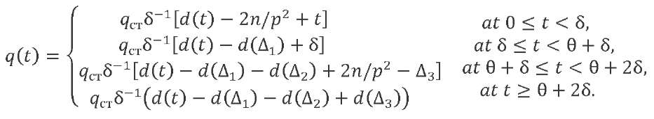 (13)
(13)
The law of variation of the oscillator accelerations can be obtained from double differentiation in time of expression (13). Let us introduce function ![]() . We differentiate and record the result taking into account the number of the oscillation tone:
. We differentiate and record the result taking into account the number of the oscillation tone:

 (14)
(14)
We rewrite the expression for the frequency of damped natural vibrations:
![]() (15)
(15)
To determine the accelerations of the LV points, we differentiate twice (6):
 (16)
(16)
Let us express the accelerations of the generalized coordinates from the first two equations of system (7) taking into account (8) and (9). We represent the accelerations of the points of the LV axis that it acquires through moving as a rigid body:
 (17)
(17)
In addition, we take into account the law of variation of function 𝑅(𝑡) from time:
We get:
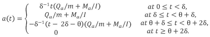 (18)
(18)
For accelerations of generalized coordinates corresponding to the elastic vibration tones, as a result of double differentiation of expression (13), taking into account (14), we obtain:
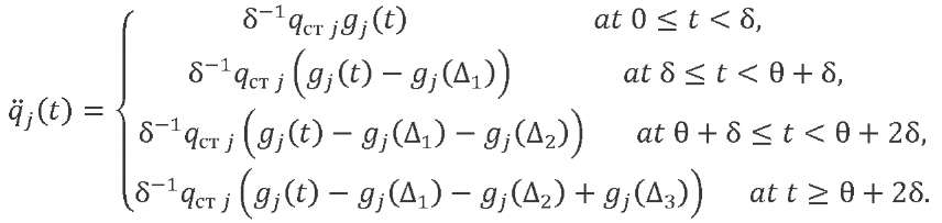 (19)
(19)
Taking into account (16) and (17), the law of variation in the accelerations of the elastic LV axis points under the action of a trapezoidal wind gust will have the form:
 (20)
(20)
where 𝑎(𝑡) is determined from expression (18), 𝑞̈𝑗 (𝑡) — from expression (19).
While investigating the LV elastic modes, damping is traditionally taken on the basis of the data obtained from the results of full-scale dynamic tests and presented in the form of values of logarithmic decrements 𝐷𝑗 . Then, the coefficient determining the damping parameter and included in expressions (14) and (15) can be calculated from formula:
 (21)
(21)
The change in generalized coordinate 𝑞𝑗 included in formula (19) under the action of a statically applied generalized force 𝑄0𝑗 is determined from expression:
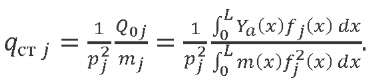 (22)
(22)
Taking into account (14), (15), (18), (19), (21), (22), formula (20) is an analytical expression that defines the functions of the acceleration change over time for the points of the LV axis under the action of an external transverse aerodynamic force varying according to the trapezoidal law, taking into account the impact of dissipative forces.
Knowing the law of acceleration variation, it is possible to determine the dynamic, and then the total structure loads acting in the LV sections using the known methods [4]. We calculate the bending moment due to inertial forces from the elastic modes of the LV structure:
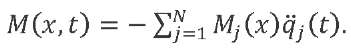 (23)
(23)
Here, 𝑀𝑗(𝑥) — function of distributing a unit (with acceleration 𝑞̈𝑗(𝑡), equal to one) bending moment for the 𝑗-th vibration tone along the LV length. It can be found from formula:
 (24)
(24)
As noted above, for the modal analysis in this work, the FE method was used. This approach is due to the fact that in practice, the dynamic LV model has rather complicated structure. It includes substructures, and their own dynamics cannot be neglected. Substructures can be attached to the LV body in one section, or be located parallel to the longitudinal axis of the LV and have several attachment points. In this case, the calculation of dynamic characteristics in a continuum setting is a complex mathematical problem. In addition, dynamic models of individual substructures are presented by development companies in a condensed (matrix) form in the Nastran format. For this reason, it will be optimal to use the Nastran engineering analysis software package to calculate the dynamic characteristics of the structure.
However, the use of standard FE analysis programs for the calculation of dynamic loading is fraught with certain difficulties. These include the need to pre-construct an equivalent model of the external aerodynamic load suitable for use in the FE analysis program [15], which in itself is quite difficult. In addition, there are difficulties associated with processing the calculation results. The use of the postprocessor functionality for analyzing the results is extremely time-consuming and requires a large number of manual operations. Another way involves the application of additional software for processing large array of numeric data5. In this paper, an approach is proposed in which the FE analysis program is used only for modal analysis. In this case, dynamic loading is calculated using specially developed software that allows you to vary external loads and automatically process the calculation results.
For a complex LV design, equations (7) retain their form [3]. The standard output information of the Nastran program can be the basis for obtaining the parameters of an equivalent system of oscillators, LV mass and moment of inertia, as well as for calculating the generalized forces included in the third equation of system (7). To form the left side of the third equation in (7), the values of natural frequencies 𝑝𝑗 (Radians) and generalized masses 𝑚𝑗 (Generalized mass) are required. To determine the generalized forces in the right part of the third equation in (7), the eigenmode functions 𝑓𝑗(𝑥) (Eigenvector) are needed. When calculating dynamic inertial loads according to (23), instead of (24), it is more convenient to use unit inertial loads (forces and moments), which are output by the Nastran program after the standard application of forces when calculating eigenforms and frequencies. Unit inertial loads are output separately for each vibration tone and multiplied by the square of the natural frequency, which should be taken into account for their correct use.
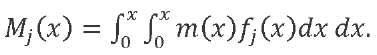
Research Results. To carry out test calculations, a medium class tandem launcher is considered. Figure 2 shows the type of functions of linear bending stiffness 𝐵(𝑥) and mass 𝑚(𝑥), as well as the distribution of concentrated masses  along the length of the considered LV (the Dirac delta function is denoted by Δ).
Fig. 2. Distribution of mass and stiffness characteristics along the LV length:
linear mass (a), concentrated mass (b), bending stiffness (c)
To check the obtained analytical solutions under the impact of a trapezoidal external load, the dynamic LV accelerations are calculated according to formula (20), taking into account (14), (15), (18), (19), (21), (22). At the same time, 5 elastic tones of natural transverse LV vibrations are considered. Characteristics 𝑝𝑗, 𝑚𝑗 and 𝑓𝑗(𝑥) were obtained from the calculation results in the MSC Nastran software package using the solution sequence for modal analysis of natural vibrations (SOL 103). The LV dynamic finite element model is presented as a set of beam elements with various inertial and stiffness characteristics. The following elements are elastically or rigidly attached to the beam elements:
The finite element LV model includes about 1000 components. The elements simulating restraints were not used to preserve the ability of the LV to move as a rigid body.
According to the same finite element LV model in the MSC Nastran software package, the accelerations are calculated through the SOL 119 solution sequence used for modal transient analysis. At the same time, all tones of natural vibrations in the range up to 100 Hz were taken into account in the modal decomposition. The aerodynamic load is represented by transverse linear loads distributed over all beam elements simulating the LV structure. In addition, the trapezoidal law of the aerodynamic load variation over time is given.
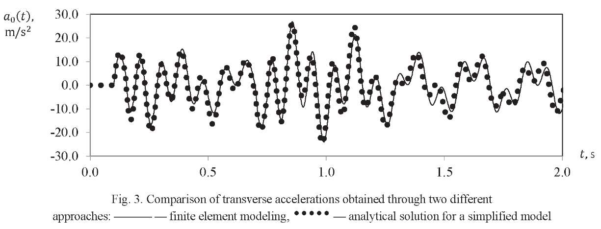
Figure 3 shows the results of a comparative analysis of accelerations obtained using two different approaches 𝑎0(𝑡) = ÿ(𝑡, 𝑥0) of a certain point of the LV axis with coordinate 𝑥𝑥 = 𝑥𝑥0. It can be seen that the following two solutions agree well:
The peak value of the bending moment selected from the time process determines the level of equivalent forces taken to carry out the strength calculation, and acts as a variable parameter when changing the parameters of external action in the transverse direction [16].
Dependences are obtained based on the values of dynamic accelerations (Fig. 4). They show how the change in peak bending moment 𝑀 or different LV sections are related to parameter θ, which characterizes the gust duration. In Figure 4, the bending moment values are presented in the form of dimensionless quantities 𝑀∗. They are calculated through dividing the dimensional bending moment by the maximum value for a given section (e.g., for section 𝑥 = 0.3𝐿 maximum value 𝑀max = 4.6 ∙ 105 N ∙ m), found when value θ varies over the entire range under consideration.
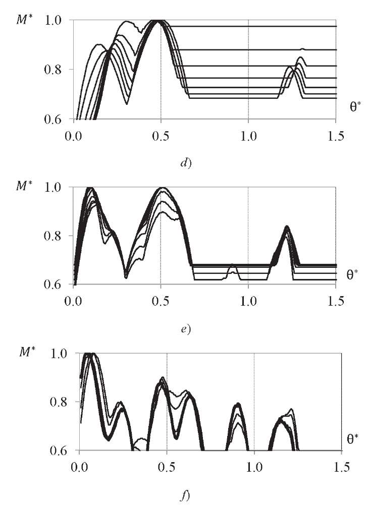
Fig. 4. Dependence of the value of dimensionless bending moment 𝑀∗
on the duration of wind gust θ∗, expressed in fractions of period 𝑇1 for various LV sections:
zone 1 (𝑥 = 0.0 − 0.2𝐿) (a); zone 2 (𝑥 = 0.2𝐿 − 0.4𝐿) (b);
zone 3 (𝑥 = 0.4𝐿 − 0.55𝐿) (c); zone 4 (𝑥 = 0.55𝐿 − 0.75𝐿) (d);
zone 5 (𝑥 = 0.75𝐿 − 0.9𝐿) (e); zone 6 (𝑥 = 0.9𝐿 − 𝐿) (f)
So, on the graphs, the duration of the gust action is represented by dimensionless value θ∗ obtained through dividing parameter θ by period 𝑇1 of the first tone of the LV vibrations. Each line of the graph corresponds to one section of the LV. All LV sections are grouped according to the nature of function 𝑀∗(θ∗) and are shown on various graphs, and the LV length is appropriately divided into zones (Fig. 5).
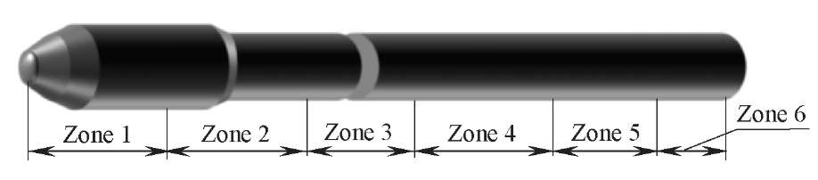
Fig. 5. LV cross-section zones
It can be seen from Figure 4 that for the first zone, the maximum bending moment is reached already at θ values at least 15% of period 𝑇𝑇1 of the first vibration tone. For the second and third zones — slightly more than half of period 𝑇1. A further increase in θ values does not affect the magnitudes of the maximum values of the bending moment. For zones 4-6, the maximum value of the bending moment turns out to be local and is within the zone of θ values close to the value of half of period 𝑇1 of the first tone of the LV vibrations. The results obtained fully correspond to the results of finite element modeling carried out earlier6.
Thus, to obtain the maximum values of the bending moment in the sections of the considered LV, a dynamic analysis of the behavior of the structure with external action in the form of a wind gust of is required. Its duration is determined by parameter θ, close in value to half of the period of the first tone of the LV vibrations.
Discussion and Conclusions. Using the superposition method, analytical solutions are obtained that describe the motion of a one-degree-of-freedom system, which is affected by the friction force and an external force varying according to the trapezoidal law. The method of application of the obtained analytical solutions for systems with many degrees of freedom is given. A good coincidence of two types of solutions is shown:
It is shown that analytical solutions can be used to analyze dynamic force factors to select the duration of a wind gust, under the impact of which maximum loads are achieved in the sections of the LV structure. Similarly, it is possible to analyze the overloads that are achieved in the LV sections (e.g., at the installation points of measurement systems).
In addition, the proposed methodology provides building a full cycle of the load analysis pre-calculation in the case when an analytical representation of the external dynamic load is possible. The load analysis based on analytical solutions is very economical in terms of calculation time, and it can be a remarkable alternative to finite element modeling at the design stage, when a large number of combinations of external loads and configurations of the design under development are studied. Finite element analysis of the detailed model in this case can be used as a refine final calculation
1. Likhoded AI. Dinamika konstruktsii i opredelenie nagruzok. Korolev: Izd-vo AO TSNIImash; 2020. 239 p. (In Russ.)
2. Kolesnikov KS. Dinamika raket. Moscow: Mashinostroenie; 2003. 520 p. (In Russ.)
3. Biderman VL. Teoriya mekhanicheskikh kolebanii. Moscow: URSS; 2017. 416 p. (In Russ.)
4. Yablonskii AA. Kurs teoreticheskoi mekhaniki. Moscow: Integral-Press; 2007. 603 p. (In Russ.)
5. Malykhina OI. Avtomatizatsiya obrabotki rezul'tatov konechnoehlementnogo analiza nagruzheniya konstruktsii raketno-kosmicheskoi tekhniki. In: Proc. VII Sci.-Tech. Postdoctoral Conf., Mission Control Center. Korolev: TSNIIMash; 2017. P. 427–434. (In Russ.)
6. Malykhina OI, Glugovskii MS. Analiz vliyaniya profilya poryva vetra na velichinu korpusnykh nagruzok rakety-nositelya v poletnykh sluchayakh nagruzheniya. In: Proc. VI All-Russian Sci.-Tech. Conf. Samara. 2019;1:133–138. (In Russ.)
1. Основы отработки прочности ракетно-космических конструкций / А. В. Кармишин, А. И. Лиходед, Н. Г. Паничкин, С. Н. Сухинин. — Москва : Машиностроение, 2007. — 480 с.
2. Johnson, D. L. The Role of Terrestrial and Space Environments in Launch Vehicle Development / D. L. Johnson, W. W. Vaughan // Journal of Aerospace Technology and Management. — 2019. — Vol. 11. — e4719. https://doi.org/10.5028/jatm.v11.1088
3. Об особенностях расчета нагрузок для конструкций с переменными массово-инерционными характеристиками / А. В. Анисимов, С. Н. Золкин, А. И. Лиходед [и др.] // Космонавтика и ракетостроение. 2012. — № 2 (67). — С. 120–128.
4. Гладкий, В. Ф. Динамика конструкции летательного аппарата / В. Ф. Гладкий. — Москва : Наука, 1969. — 495 с.
5. Suresh, B. N. Aerodynamics of Launch Vehicles / B. N. Suresh, K. Sivan / In book: Integrated Design for Space Transportation System. — New Delhi : Springer, 2015. — P. 391–454. https://doi.org/10.1007/978-81-322-2532-4_10
6. Clark, J. B. Statistical Analysis of Atmospheric Flight Gust Loads Analysis Data / J. B. Clark, M. C. Kim, A. M. Kabe // Journal of Spacecraft and Rockets. — 2000. — Vol. 37. — P. 443–445. https://doi.org/10.2514/2.3602
7. Kim, M. C. Atmospheric Flight Gust Loads Analysis / M. C. Kim, A. M. Kabe, S. S. Lee // Journal of Spacecraft and Rockets. — 2000. — Vol. 37. — P. 446–452. https://doi.org/10.2514/2.3603
8. Linearized Aeroelastic Gust Response Analysis of a Launch Vehicle / F. Mastroddi, F. Stella, D. Cantiani, F. Vetrano // Journal of Spacecraft and Rockets. — 2011. — Vol. 48. — P. 420–432. https://doi.org/10.2514/1.47268
9. Jayasidhan, A. K. Dynamic Response of a Launch Vehicle to Wind Gust / A. K. Jayasidhan, J. Rose, R. Neetha // International Journal of Engineering Development and Research (IJEDR). — 2015. — Vol. 3. — P. 1–6.
10. Золкин, С. Н. Исследование нагружения ракеты-носителя тяжелого класса при движении в плотных слоях атмосферы / С. Н. Золкин // Труды МАИ. — 2011. — № 45. — С. 1–12.
11. Sengupta, D. A simplified model for hydroelasticity of containerships / D. Sengupta, R. Datta, D. Sen // Journal of Engineering Mathematics. — 2021. — Vol. 129. — P. 1–30. https://doi.org/10.1007/s10665-021-10142-2
12. Xiang, Z. Synergic identification of prestress force and moving load on prestressed concrete beam based on virtual distortion method / Ziru Xiang, Tommy Chan, David Thambiratnam, Andy Nguyen // Smart Structures and Systems. — 2016. — Vol. 17. — P. 917–933. https://doi.org/10.12989/sss.2016.17.6.917
13. Механика контейнерного старта ракеты при действии поперечных нагрузок / А. А. Александров, Д. К. Драгун, А. И. Забегаев, В. В. Ломакин // Инженерный журнал: наука и инновации. — 2013. — № 3 (15). С. 1–10.
14. Кирилин, А. Н. Проектирование, динамика и устойчивость движения ракет-носителей. Методы, модели, алгоритмы, программы в среде MathCad / А. Н. Кирилин, Р. Н. Ахметов, А. В. Соллогуб. — Москва : Машиностроение, 2013. — 296 с.
15. Johnson, D. L. The Wind Environment Interactions Relative to Launch Vehicle Design / D. L. Johnson, W. W. Vaughan // Journal of Aerospace Technology and Management. — 2020. — Vol. 12. — e0220. — P. 1–13. https://doi.org/10.5028/jatm.v12.1090
16. Титов, В. A. Оценка влияния квазистатического изгиба конструкции ракеты-носителя на нагрузки в зоне прохождения максимального скоростного напора / В. A. Титов // Космонавтика и ракетостроение. — 2013. — № 1 (70) — С. 76–82.
Olga I. Malykhina
Samara
Malykhina O.I. Analytical solution to approximate equations of the launch vehicle motion under the gust action for the dynamic loading calculation. Advanced Engineering Research (Rostov-on-Don). 2022;22(1):30-41. https://doi.org/10.23947/2687-1653-2022-22-1-30-41


Advanced Engineering Research (Rostov-on-Don)
ISSN 2687-1653 (Online)
Contact with: Publisher / Editorial Office of the Journal
Publisher: Don State Technical University - DSTU, Rostov-on-Don, Russia - https://donstu.ru/en/
Editor-in-Chief: Alexey N. Beskopylny, Dr.Sci. (Eng.), Professor, Vice-Rector, Don State Technical University (Rostov-on-Don, Russia)
Don State Technical University
1, Gagarin Sq., Rostov-on-Don, 344003, Russia
tel.: +7 (863) 2738-372, e-mail: vestnik@donstu.ru
16+
Processing of personal data


