


Contents
Scroll to:
https://doi.org/10.23947/2687-1653-2022-22-2-150-160
Scroll to:
Introduction. The movement of the carrier and external factors (the effects of the atmosphere, temperature and pressure) degrade significantly the image quality of the servo optoelectronic systems (OES) and the positioning accuracy of the emitting OES. The issues of image quality improvement and the probability of keeping the image of the observation object (OO) on the optical axis of the servo EOS are considered.
Materials and Methods. The development of an automatic control system for an optoelectronic device (ACS OED) involved solving a multi-criteria optimization problem taking into account a number of conflicting technical-andeconomic (TE) requirements. The determination of tolerated dynamic errors (TDE) of image stabilization was a key issue in the development of on-board optoelectronic devices (OOED). Lagrange equations of the second kind and the mixed Gilbert method made it possible to obtain a mathematical model of the CO OED. Then, the decomposition of a two-link ACS with nonlinear cross-couplings in the CO was performed. A functional diagram of the image formation model of the OOED was presented. The parameters of the matrix photodetector and the requirements for the dynamic error of the ACS OED, taking into account the permissible MTF of the OED, were listed. The functions of transferring modulation, as well as linear, harmonic and vibrational shift of the image corresponding to the permissible and achieved TDE were visualized. Logarithmic frequency characteristics were created in the Mathcad environment. The two-link control system of the OED with the specified parameters of the CO for the considered movement was presented as two independent azimuth and elevation control channels.
Results. The processes of control of the on-board optoelectronic system in the stabilization and tracking modes were described. To study the dynamics of spatial control of the OOEP in accordance with the ACS methodology, a computer simulation model (CSM) of the digital automatic control systems (DACS) of the OED was developed. It was implemented in the Matlab environment and consisted of CSM CO, drives, proportional-integral-derivative (PID) controllers taking into account non-linearities, a central computing device (CCD), a guidance software device, a CSMcarrier that implemented the equations of motion. Harmonic vibrations of the carrier were described. The errors of tracking and stabilization in the tracking mode with an additional control action introduced in the form of a constant speed were determined. The dynamics of spatial control of the OOED was investigated. A computer simulation model of a digital automatic control system of an optoelectronic device, the results of modeling the DACS OED without considering the board movement, and the processes of OED control subject to movement were visualized.
Discussion and Conclusions. The stabilization accuracy was calculated for the studied cases. It was established that the stabilization tens of times exceeded the previously stated indicators, and it tens of times reduced the requirements for the convergence of the laser beam and the laser radiation power when developing the optical path of the product in question. The proposed CSM can be used in the development of the on-board optoelectronic systems. In this case, the application of the presented methodology and CSM will help to reduce labor costs and minimize errors.
Burdinov K.A., Shashkina K.M., Shaghaei E. Investigation of ACS image stabilization of on-board optoelectronic guidance and tracking devices. Advanced Engineering Research (Rostov-on-Don). 2022;22(2):150-160. https://doi.org/10.23947/2687-1653-2022-22-2-150-160
Introduction. When designing modern on-board optoelectronic devices (OED) and complexes, methods of computer modeling of optoelectronic systems (OES) are widely used. Such authors as Yu. G. Yakushenkov, V. V. Tarasov, I. P. Torshina, V. P. Ivanov, V. A. Baloev, V. A. Ovsyannikov, V. L. Filippov, worked on these tasks. Computer modeling enables to solve the problems of rational choice of the structure, parameters, and element base of the OES, providing the required performance indicators under specified constraints without expensive field studies and tests.
The movement of the carrier and external factors (temperature, pressure) degrade significantly the image quality of the servo OES and the positioning accuracy of the emitting OES. The probability of holding the image of the object of observation (OO) on the optical axis of the tracking OES is reduced. For emitting OES, the positioning accuracy and the probability of performing observation tasks are reduced. To hold the image in vision or in the irradiation sector, it is required to capture a fairly large solid viewing angle. Hence, it is required to increase the dimensions of optical systems and power electronics capacities. To avoid this, controlled radiating OES is used. The above-mentioned features of the OED limit the development of the ACS OED. This problem was considered by V. A. Strezhnev, V. M. Matrosov, A. S. Zemlyakov, N. N. Malivanov, E. I. Somov, A. I. Malikov, V. A. Krenev, A. I. Karpov, D. A. Molin, A. V. Mikhalitsyn. When designing controlled OED operating in guidance and tracking modes, the following fact was established: the guidance time and the accuracy of stabilization of the optical axis, as well as the dynamics of the OED subsystems affect significantly the image quality.
Thus, the task of minimizing the time and increasing the accuracy of pointing and holding the image of the OO in vision of the controlled OED is a challenge. In this regard, the following is required:
The work aimed at improving the accuracy characteristics and image quality of OED operating in the guidance, stabilization and tracking modes, due to the rational choice of their parameters during synthesis and modeling.
Materials and Methods. The development of ACS OED started with solving a multi-criteria optimization problem that took into account conflicting technical-and-economic (TE) requirements. In the development of study [1], a modified method of designing a self-propelled ACS OED was proposed. For the quality criterion of the ACS, we took a set of dynamic characteristics of control channels that met the conditions:
 (1)
(1)
Here,  — permissible and implemented modulation-transfer function (MTF) of the OED at the Nyquist frequency,
δ(ω), δдоп — amplitude frequency response of cross-couplings and its acceptable decomposition value;
 — permissible and steady-state values of the dynamic errors of the ACS in angle and angular velocity under the action of disturbances under conditions close to the actual operation of the ACS;
к = 1, 2, … — number of the control channel providing image quality;
Мдоп = 1,05–1,25 — oscillation index,
Δφ, ΔL — stability margins in phase and amplitude.
The key issue in the development of the OED is the determination of tolerated dynamic errors (TDE) of image stabilization.
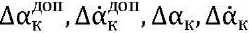
The image formation scheme of the on-board optoelectronic device (OOED) is shown in Figure 1.
Fig. 1. Functional diagram of the OOED imaging model: OO — object of observation;
OS — optical system; MPD — matrix photodetector;
ACD — amplifying-converting device; ISS — image stabilization system
The MTF OOED should meet the condition that provides acceptable image quality [2]:
 (2)
(2)
Here, 𝑇ОЭC(ν) — MTF OED; N — spatial frequency;  — admissible MTF OOED; 𝑇aт(ν) — atmospheric MTF; 𝑇oб(ν) — lens MTF; 𝑇фп(ν) — photodetector MTF; 𝑇упу(ν) — optical information conversion function MTF [1]; 𝑇ССИ(ν) — MTF of the image shift (dynamic error of the ISS), depending on the type of dynamic displacement of the image: linear (Л) — 𝑥(𝑡) = 𝑉𝑡, harmonic (Г) — 𝑥(𝑡)=𝑎0𝑠𝑖𝑛(𝑡), random (R), and defocusing.
The permissible MTF of the image stabilization system includes tracking, stabilization, vibration protection (VPS) and automatic focusing (AFS) systems [3]:
 (3)
(3)
Here, 𝑇Л(𝑁) — image linear shift error; 𝑇Г(𝑁) — sinusoidal error amplitude; 𝑇В(𝑁) — average value of vibration amplitude error; 𝐽0 — zero-order Bessel function of the first kind; 𝐽1(Δф) — Bessel function of the first kind of the first order; Δф — focus error (mm); σ — average value of wave aberration in fractions of a wavelength; λср — average wavelength of the spectral range.
Let us assume that each subsystem of the ACS must make the same amount of change in the image quality of the OED and 𝑇ст(𝑁) = сonst during observation. Then, the definition of acceptable MTF R, VPS, AFS, will be simplified (3):
 (4)
(4)
We expand functions 𝑇Л(𝑁),𝑇Г(𝑁),𝑇В(𝑁),𝑇Ф(𝑁) (3) into a series and obtain expressions that determine the TDE:
 (5)
(5)
Here, νн — Nyquist frequency.
The limiting spatial frequency that the OED should resolve during the observation process is determined by the Johnson criterion:
 (6)
(6)
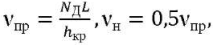
where νпр — angular (bar/rad) limiting spatial frequency; 𝑁Д — number of resolution elements (Johnson numbers); L — distance to OO; hкр — critical size of OO.
When decomposing, all members of the series are discarded, except the first ones, therefore, the tolerances obtained should be revised by gradient descent.
The above reasoning allowed us to determine the accuracy of image stabilization of the onboard optoelectronic system (OOES) for tracking and stabilization modes. A methodology and a program for calculating MTF and tolerances were developed (Patent RU20216603401).
Let us denote requirements for the dynamic error of the ACS OED, taking into account the permissible MTF OED. Initial data for calculation:
MPD parameters:
Figure 2 shows the MTF of linear, harmonic and vibrational shift of the image corresponding to the permissible and obtained DDP of the ACS OOED.
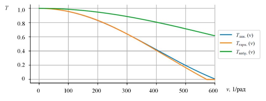
Fig. 2. Modulation transfer functions 𝑇𝑗доп(ν)
In accordance with (3)–(5) and the initial data for the calculation, we determined: νпр = 600 rad–1 of the OOED observation channel in the infrared region with a detection probability of Р = 0.8. For MTF OOED and TDE ACS: ΔαЛ = 3.5 ang. min , ΔαГ = 3.1 ang. min , ΔαВ = 3.0 ang. min.
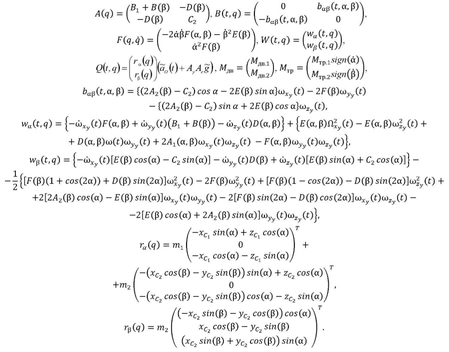
On the basis of the Lagrange equations of the second kind and the mixed Gilbert method, a mathematical model of the SO OED [4] of guidance and tracking was obtained in the form of three information channels driven by DBM electric motors along the gimbal axles. We presented it in a matrix form2:
 (7)
(7)
Here, 𝑞 = (α β)𝑇, α, β — CO rotation angles in azimuth and elevation.
The next stage of development was the decomposition of doubly connected ACS [5] with nonlinear cross couplings in the CO, which is the studied OED. The linearized equations of motion with respect to the trajectory have the form:
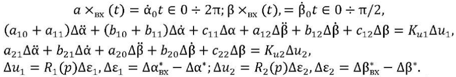 (8)
(8)
Having constructed the variable coefficients of system (8), we determine their values at t = tк* at “dangerous” points at which the parameters change significantly or change signs in the range of angles (β* = 0 ÷ π/2, α* = 0 ÷ 2π). Then, reducing system (8) (for t = tк*) to a system with constant parameters and using Cramer's rule, we express it in the form of transfer functions (TF) at points t = tк*:
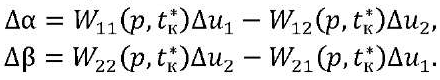 (9)
(9)
The obtained TF (9) taking into account (8) for each selected moment of time (t = tк*) can be presented in the form of a block diagram with direct cross couplings (CC, Fig. 3). From now on, for simplicity of writing, we denote TF as Wкij(р) = Wij(р,tк*).
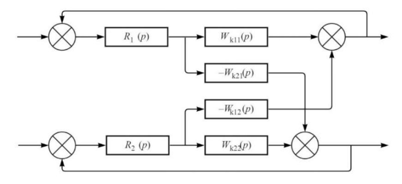
Fig. 3. Structural diagram of doubly connected ACS
We evaluate the CC ACS by their frequency response (FR). For this purpose, we write down the TF of the open system, taking into account the 2nd closed control channel when Δβвх = 0 (Fig. 4).
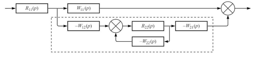
Fig. 4. Structural diagram of ACS, open on one control channel
Let us build hodograph 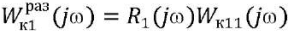 and tubes around it with radii for each moment of time tк*:
 (10)
(10)
Taking into account (10) and the Nyquist criterion, it is possible to judge the stability of the ACS (1), (2) and the influence of the CC on its stability in the range of scanning angles (3).
As a result, for each (tк*-th), we determine the CC time:
 (11)
(11)
Let us consider the CC ACS that satisfy the decomposition conditions.
According to (8), (11), from the CO mass geometry data, for 11 selected points in time, we determined (tк* 0; 0.89; 1.35; 1.58; 1.71; 2.3; 2.97; 3.8; 4.5; 4.75; 6.28 s). We built aij(t), bij(t), cij(t). Logarithmic frequency response (LFR)
δк(ω) (k = 1.11) was created in the Mathcad environment (Fig. 5).
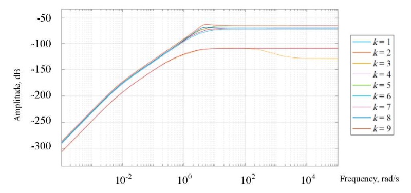
Fig. 5. Logarithmic frequency response δк(ω)
Figure 5 shows that the entire LFR set does not exceed –50 dB. From the analysis of LFR δк(ω), we have the results presented below.
The following was determined: max δк(ω) = 0.0136 (–37.3 dB) < δдоп = 0.0335 (–29.5 dB), ΔL = Mдоп / (Mдоп +1) = 0.535 (–5.43 dB) at М10 = М20 = 1.1; Mдоп = 1.15.
Hence, a doubly connected control system (8) of the OED with the given parameters of the CO for the motion in question can be presented as two independent control channels in azimuth and elevation angle.
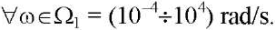
Research Results. Figures 6 and 7 show the OOED control processes in stabilization and tracking modes. The scale of the misalignment graphs has been increased by 600 times. The graphs of the program control and the output values visually coincide.
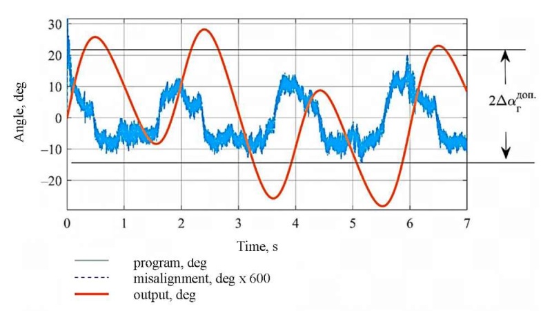
Fig. 6. OOED stabilization processes in azimuth
Fig. 7. OOED tracking processes in azimuth
We describe the harmonic oscillations of the carrier: А1 = А2 = 20 (amplitudes), Т1 = Т2 = 1 s (oscillation periods), and А1 = А2 = 120, Т1 = Т2 = 6.28 s. We indicate the load moments: Мдв1 = 2.2 Нм, Мдв1 = 0.3 Nm. With such harmonic oscillations and load moments, the error of stabilization of the sighting axis does not exceed:
In tracking mode, with an additional control action introduced in the form of a constant speed of 12 deg/s, the error of tracking and stabilization does not exceed 1.7 ang. min in azimuth and 1.3 ang. min in elevation angle.
To study the dynamics of the spatial control of the OOED in accordance with the ACS technique, the CSM of the digital automatic control system (DACS) of a specific OED was developed (Fig. 8) [1].
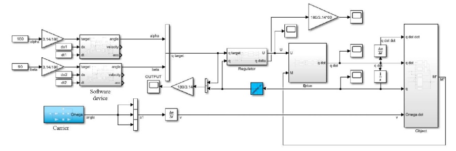
Fig. 8. Computer simulation model of a digital system for automatic control of an optoelectronic device
The solution is implemented in the Matlab Simulink environment. Its elements:
Figures 6 and 7 show the results of modeling the DACS OED without taking into account the movement of the board. In this case:
Figure 9 shows the control processes of the OED, taking into account its movement. The azimuth guidance error is 2 ang. min, the elevation angle error is 5 ang. min. The error of tracking and stabilization is 0.8 ang. min in azimuth, 1.3 ang. min in elevation angle.
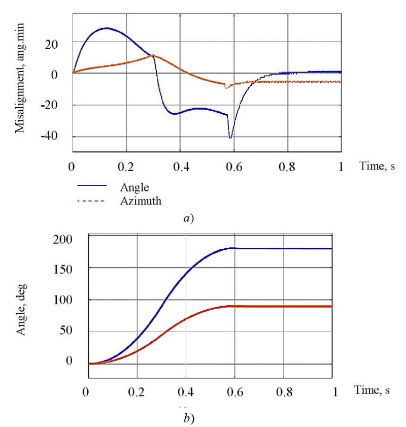
Fig. 9. Simulation results of the system in two-channel guidance mode (degrees):
a — system misalignment;
b — transient schedules. In second case, schedules of program control (alpha target, beta target)
and output value (alpha, beta) visually coincide
Discussion and Conclusions. The results obtained are presented below.
We calculated the required stabilization accuracy for each of the presented cases using formula 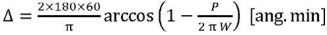 and made Table 1.
Table 1
Comparison of required stabilization accuracy
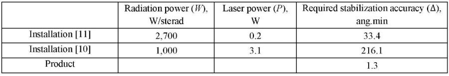
Thus, the accuracy of stabilization of the proposed system was ten times higher than that required in papers [9][10]. And this reduces the requirements for the convergence of the laser beam and the laser radiation power tenfold when developing the optical path of the product in question.
List of abbreviations and conventions
OES — optoelectronic system,
OED — optoelectronic device,
OO — object of observation,
CSM — computer simulation model,
ACS — automatic control system,
MTF — modulation transfer function,
TDE — tolerated dynamic error,
ISS — image stabilization system,
MPD — matrix photodetector.
1. Program for calculating the modulation transfer function of an optoelectronic device based on UAV: RF patent 2021660340, 2021. Innopolis University. (In Russ.)
2. Burdinov KA, et al. Matematicheskaya model' i sintez sistemy avtomaticheskogo upravleniya bortovogo optiko-ehlektronnogo pribora. In: Proc. XII All-Russian Congress on Fundamental Problems of Theoretical and Applied Mechanics, Ufa, 2019. P. 190–192. (In Russ.)
3. Directed Infrared Countermeasure (DIRCM). EMSOPEDIA. emsopedia.org . URL: https://www.emsopedia.org/entries/directed-infrared-countermeasure-dircm/ (accessed: 01.05.2022).
1. Методика разработки и испытаний систем управления и виброзащиты бортовых оптико-электронных приборов / В. А. Балоев, К. А. Бурдинов, А. И. Карпов [и др.] // Оптический журнал. — 2021. — Т. 88, № 3. — С. 13–26 https://doi.org/10.17586/1023-5086-2021-88-03-24-36.
2. Молин, Д. А. Применение функции передачи модуляции для оценки допустимых характеристик оптикоэлектронных приборов / Д. А. Молин // Вестник Казанского государственного технического университета им. А. Н. Туполева. — 2011. — № 1. — С. 68–75.
3. Сокольский, М. Н. Допуски и качество оптического изображения / М. Н. Сокольский. — Ленинград : Машиностроение, 1989. — 220 с.
4. Балоев, В. А. Имитационное моделирование двухступенчатой системы управления сканирующим устройством бортового базирования / В. А. Балоев, А. И. Карпов, В. А. Кренев [и др.] // Оптический журнал. — 2017. — Т. 84, № 3. — С. 6–14.
5. Гаркушенко, В. И. Синтез многосвязной нестационарной системы управления при неполной информации / В. И. Гаркушенко // Вестник Казанского государственного технического университета им. А. Н. Туполева. — 2003. — № 3. — С. 47–49.
6. Bangura, M. Real-time model predictive control for quadrotors / M. Bangura, R. Mahony // IFAC Proceedings Volumes. — 2014. — Vol. 47. — Р. 11773–11780 https://doi.org/10.3182/20140824-6-ZA-1003.00203
7. Real-time long range trajectory replanning for MAVs in the presence of dynamic obstacles / Geesara Kulathunga, R. Fedorenko, S. Kopylov, A. Klimchik // URL: https://ieeexplore.ieee.org/document/9162605 (accessed: 13.06.2022) https://doi.org/10.1109/ACIRS49895.2020.9162605.
8. Optimization-Based Trajectory Tracking Approach for Multi-Rotor Aerial Vehicles in Unknown Environments / Geesara Prathap Kulathunga, Hany Hamed, D. Devitt, A. Klimchik // IEEE Robotics and Automation Letters. — 2022. — Vol. 7. — P. 4598–4605.
9. Development of a mid-infrared laser for study of infrared countermeasures techniques / H. H. P. Th. Bekman, J. C. van den Heuvel, F. J. M. van Putten, R. Schleijpen // URL: https://www.spiedigitallibrary.org/conferenceproceedings-of-spie/5615/0000/Development-of-a-mid-infrared-laser-for-study-of-infrared/10.1117/12.578214. short?SSO=1 (accessed: 13.06.2022) https://doi.org/10.1117/12.578214
10. Optical countermeasures against CLOS weapon systems / A. Toet, K. W. Benoist, J. N. J. van Lingen, R. H. M. A. Schleijpen // URL: https://www.spiedigitallibrary.org/conference-proceedings-of-spie/8898/1/Opticalcountermeasures-against-CLOS-weapon-systems/10.1117/12.2028342.short (accessed: 13.06.2022) http://dx.doi.org/10.1117/12.2028342
Innopolis University, 1, Universitetskaya St., Innopolis
Innopolis University, 1, Universitetskaya St., Innopolis
Innopolis University, 1, Universitetskaya St., Innopolis
Burdinov K.A., Shashkina K.M., Shaghaei E. Investigation of ACS image stabilization of on-board optoelectronic guidance and tracking devices. Advanced Engineering Research (Rostov-on-Don). 2022;22(2):150-160. https://doi.org/10.23947/2687-1653-2022-22-2-150-160


Advanced Engineering Research (Rostov-on-Don)
ISSN 2687-1653 (Online)
Contact with: Publisher / Editorial Office of the Journal
Publisher: Don State Technical University - DSTU, Rostov-on-Don, Russia - https://donstu.ru/en/
Editor-in-Chief: Alexey N. Beskopylny, Dr.Sci. (Eng.), Professor, Vice-Rector, Don State Technical University (Rostov-on-Don, Russia)
Don State Technical University
1, Gagarin Sq., Rostov-on-Don, 344003, Russia
tel.: +7 (863) 2738-372, e-mail: vestnik@donstu.ru
16+
Processing of personal data


