


Contents
Scroll to:
https://doi.org/10.23947/2687-1653-2022-22-3-252-260
Scroll to:
Introduction. Pressure-operated thick-walled hull structures are the most common type of high-duty welded structures. When these structures are loaded with internal pressure, a complex biaxial stress field arises in them, which is summed up with the fields of residual welding stresses. Therefore, when selecting a technology for manufacturing critical welded structures, the results obtained during conventional uniaxial tests of samples are insufficient. The variety of factors affecting the performance of structures, and the difficulties of separate assessment of their influence, caused the need to maximize the approximation of experimental conditions to the real working conditions of the structure.
Materials and Methods. Testing of full-scale structures has a number of advantages, but they are extremely expensive, and, as a rule, only one, the weakest link, is identified, the bearing capacity of the other structural elements remains unclear. For testing, UDI radiometric installations designed for different sample sizes were used. The presented installations allow testing samples of various shapes, types of welded joints (butt, T-bar), changing the position of welded parts.
Results. Without rejecting the results obtained during the testing of full-scale structures in the works of the Bauman Moscow State Technical University, DSTU, NRC «Kurchatov Institute» – CRISM «Prometey», and the authors proposed to conduct the basic scope of the research on individual structural elements that would reflect the characteristic features of loading, manufacturing technology, and operating conditions. The design of the «fitting-sheet» connections was applied, which made it possible to increase the indicators of the failure initiation and propagation to the level of the base metal.
Discussion and Conclusions. Schemes of structures for obtaining a biaxial tension or bending field in samples were presented. Samples tested according to the proposed schemes allowed us to draw conclusions about the performance of welded joints under conditions close to the actual operation of the structures under study. The proposed test scheme is used by research laboratories in our country and around the world.
Lyudmirsky Yu.G., Assaulenko S.S., Kramskoi A.V. Methods and Equipment for Experimental Evaluation of the Performance of Shell and Hull Structures. Advanced Engineering Research (Rostov-on-Don). 2022;22(3):252-260. https://doi.org/10.23947/2687-1653-2022-22-3-252-260
Introduction. Thick-sheet hull pressure-operated structures are the most common type of high-duty welded structures. When these structures are loaded with internal pressure, a complex, predominantly biaxial stress state occurs, in which the fields of residual welding stresses are summed up with the stress fields from the external load. Under these conditions, there is often an increased sensitivity of both the base metal and welded joints to the presence of stress concentrators or a local change in the mechanical properties of the metal associated with the manufacturing process, which can cause a sharp decrease in strength. Currently, despite a number of fundamental studies on the strength of welded sheet and hull structures, there is still insufficient systematic data on the patterns of resistance to the initiation and development of destruction of large-sized elements of welded structures, depending on structural, technological, and operational factors. Therefore, for the choice of material and manufacturing technology of critical platework, the data obtained through conventional uniaxial tests of samples is sometimes insufficient. The variety of factors affecting the operability of structures and the difficulties of separate assessment of their influence necessitates bringing the course of the experiment to real conditions as close as possible. This has led to the spread of methods for testing full-size structures or their models. To conduct such tests in our country and abroad, stands equipped with sophisticated testing and diagnostic instruments have been created. One example is as follows: for testing full-size large-diameter pipes, there are stands in UralNITI, Volga Pipe Plant, VNIIST, CRISM “Prometey”, and in other laboratories. There are stands of a similar purpose in Japan. In the USA, there are more than 300 installations for testing structures operating under static and pulsating pressure.
Tests of full–scale structures have a number of advantages:
Despite the undoubted value of field tests to assess the structural strength of the product, it is extremely irrational to use such tests to study individual factors affecting the strength of the structure. The abundance of factors simultaneously affecting the course of the study makes it difficult to analyze the causes of premature fracture and does not allow us to separately assess the degree of influence of each of them. As a result of testing of full-size structures, as a rule, it is possible to identify the weakest link, whereas the bearing capacity of the rest of the sections (elements) of the structure remains unknown.
The above disadvantages can be practically eliminated if the bulk of the research is carried out on reduced-size models of shell structures. Such tests allow us to get answers to questions related to the structural strength and reliability of the product, to identify the degree of danger of the initiation and development of crack-like defects, to evaluate the effectiveness of various ways to increase durability.
Without rejecting the test results obtained on simple uniaxial samples and when testing full-scale structures at the Bauman Moscow State Technical University, DSTU, NRC “Kurchatov Institute” – CRISM “Prometey”, the authors propose to transfer the bulk of the research to testing individual structural elements that reflect the characteristic features of its loading, manufacturing technology, and operating conditions. In relation to shell and hull structures, during testing, it is required to take into account:
Materials and Methods. This paper describes the experience of designing installations for testing metal and welded joints under biaxial stress.
The analysis carried out in [1–5] has shown that the working conditions of metal and welded joints in steel-plate structures are most fully reproduced when tested under hydrostatic buckling. In this case, the sample is fixed or supported along the contour and loaded with hydrostatic pressure.
The stress state that occurs in the sample metal depends on the shape of the sample, the conditions of its fixation (pinching or loose support on the die), the shape of the die. Figure 1 shows the loading schemes and the resulting biaxial bending or stretching stresses.
When a flat sample supported along the contour of the circular hole of the die is loaded with hydrostatic pressure, a biaxial bend occurs. A significant part of the external convex surface of the sample is subject to uniform stretching with equal stress components σ1 = σ2 (Fig. 1 а). If the flat sample is securely pinched along the contour of the die hole, then biaxial stretching is applied to the biaxial bend. In the case of loading not a flat sample, but a spherical segment with a sufficiently large ratio of the diameter of the die hole to the thickness of the sample, the bending component is small, and it can be assumed that the central part of the sample is subject to the biaxial stretching with σ2/σ1 =1 (Fig. 1 b). Biaxial stretching with unequal components within the ratio σ2/σ1 =1.0...0.75 can be obtained by buckling the sample according to the scheme shown in Figure 1b, using dies with elliptical holes.
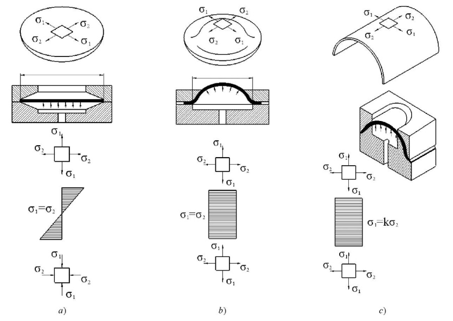
Fig. 1. Loading schemes of samples to obtain a biaxial stress field in them:
a — loading of a flat sample with equal stress components;
b — loading of a spherical segment;
c — loading of a sample in the form of a cylindrical panel
A further decrease in the ratio σ2/σ1 = (0.7… 0.3) is obtained using the scheme shown in Figure 1 b, where a cylindrical-panel sample, pinched by a flange part between the cylindrical die and the cylindrical punch, is loaded with hydrostatic pressure [3][4].
For steel-plate pressure-operated structures, two types of loading are characteristic: single (static) and low-cycle (repeated static). For the first, it is reasonable to use schemes a and b (Fig. 1). Under static loading, the scheme test can be carried out both on samples in the form of flat sheets and the pre-formed spherical segments [5–7].
Plates are preferable, since their production is less labor-intensive. Samples in the form of a spherical segment can reduce the edge effect of fixing the sample along the contour. However, the preparation of such samples requires plastic deformation, and this can cause a change in the mechanical properties of the material, which is not always correctable even by subsequent heat treatment.
When testing under low-cycle loading conditions, all three schemes shown in Figure 1 can be used. However, preference should be given to biaxial bending according to scheme a, since it provides testing large thicknesses.
The resistance to fracture nucleation and development under tension is usually evaluated using schemes b and c (Fig. 1) on pre-formed samples that are made in the form of a spherical segment or a cylindrical panel.
The environment has a particularly strong impact on the results of long-term and repeated static tests. Of great interest is the resistance of materials under repeated static loading in corrosive environments [8–10].
To study the processes of nucleation and the development kinetics of fracture in the elements of hull structures, a series of installations has been developed in DSTU together with the NRC “Kurchatov Institute” — CRISM “Prometey”: UDI–550, UDI–980, UDI–1300. Their key characteristics for biaxial bending are presented in Table 1.
Advantages of these installations:
Table 1
Characteristics of power units of installations for testing base metal and welded joints under biaxial bending conditions
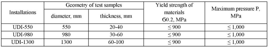
The created installations make it possible to determine the cyclic strength of various materials in air and in a corrosive environment, to obtain information about the failure pattern with different structural and technological design of welded joints of full thickness, to evaluate the efficiency of various methods to increase durability.
The design of the installations intended for testing under conditions of biaxial bending of welded joints made of sheet metal with a thickness of 20-100 mm with a yield strength up to 15 MPa is shown in Figure 2. They consist of four blocks 1, in which samples are fixed, a control panel 2 and pumping stations, which are not shown in the figure.
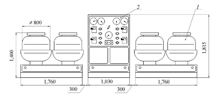
Fig. 2. Design of installations for testing under biaxial bending conditions:
1 — test installation; 2 — control panel
The basic design of the power units of UDI-550, UDI-980, and UDI-1300 installations is the same and is shown in Figure 3.
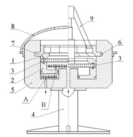
Fig. 3. UDI-type power unit of installations for testing welded joints under biaxial bending:
1 — die; 2 — hydraulic clamp; 3 — test sample;
4 — base; 5 — locking device (cup); 6 — inner ring groove;
7 — ring locking sectors; 8 — protective casing; 9 — hydraulic jack
The installation contains a die 1 and a hydraulic clamp 2, between which a sample 3 and a locking device 5 are placed, which is fixed on the base 4. The locking device is made in the form of a fixed smooth cup with an internal groove 6, in which annular locking sectors 7 (eight pcs.) are located along the entire perimeter, having an L-type shape in axial section.
The installation works as follows. The sample 3 in the form of a round disk is mounted on the hydraulic clamp 2, a die 1 is mounted on top of it. Then, eight removable annular sectors 7 are laid in the groove of the locking device 5, pressing them tightly together so as to provide minimal gaps between them.
The installation is covered with a protective casing 8. After that, the pumping station is turned on, and pressure is applied to the cavity A formed by the bottom of the locking device 5 and the hydraulic clamp 2. Under the impact of pressure, the hydraulic clamp 2 moves upwards, presses the sample 3 to the die 1, and the die — to the annular sectors 7. The sectors rest against the support surface of the annular groove and the inner surface of the cup 5, preventing the movement of the die 1, thereby fixing the sample 3 in the installation.
Then, the liquid flow is directed into the cavity B under the sample 3. Under the influence of pressure, the sample, resting on the edge of the hole in the die 1, bends, and biaxial tensile stresses arise on its outer side. The magnitude of tensile stresses on the surface is regulated by the pressure in the cavity B. The hydraulic system allows for repeated static loading of samples with a loading frequency of ten cycles per minute.
The scheme of disassembly and extraction of the sample is shown in the right part of Figure 3.
After the end of the tests, a hydraulic jack 9 is installed on the sample 3, which rests with its paws on the projections on the annular sectors 7. When connecting the jack to the hydraulic system of the installation, its piston presses on the sample and moves it together with the hydraulic clamp 2 down to the start position, which provides disassembling of the installation.
In the process of testing, the number of cycles before the failure (crack length 8–12 mm), the crack development kinetics, and the destruction of the sample (in this case, it is loss of tightness) are recorded.
The electrical and hydraulic circuits of the installations allow for static or repeated static loading. The loading cycle can be pulsating or with a positive coefficient of asymmetry. The frequency of loading samples is adjustable from two to ten cycles per minute.
In cases where the effect of a corrosive medium is of interest, it is poured into the cavity formed by the sample and the die 1. To protect against corrosion, the die should be coated with a layer of epoxy resin or varnish, or an annular rubber collar should be glued to the sample, preventing the spreading of the corrosive medium beyond the test part of the sample.
Depending on the testing purpose, samples of various types and sizes are used. Some of them are shown in Figure 4 as an example.
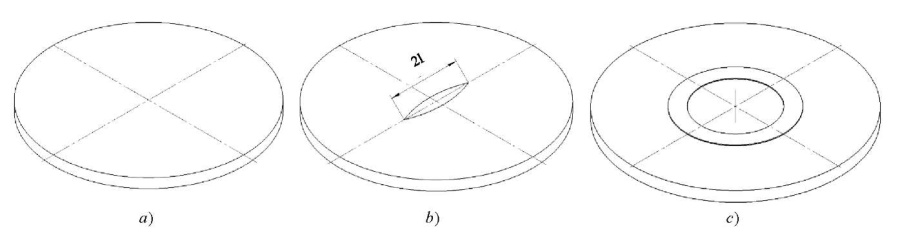
Fig. 4. Samples providing for assessment of the corrosive environment impact (3% NaCl solution):
a – from the basic; b – linear notch; c – annular notch
To assess the resistance to the nucleation and development of the base metal fracture in a biaxial stress field under the simultaneous action of a corrosive medium, it is reasonable to use smooth and notched samples. Comparative tests of these samples in air and in a 3 % NaCl solution have shown that this medium accelerates the processes of nucleation and development of fracture. When tested in air, as a rule, one crack nucleates and develops. In the presence of a corrosive medium (3 % NaCl solution), even in the presence of stress concentrators, a multifocal pattern of the nucleation and development of cracks is observed, which significantly accelerates the destruction process — by 2–2.5 times [11–13].
The paper considers a method for increasing low-cycle fatigue of welded joints of the “fitting – plate” type. It is proposed to increase durability by reducing stresses on the stretched surface, where a corrosive environment acts, through reducing the average stresses in the joint [14][15]. Figure 5 shows the proposed welded joint.
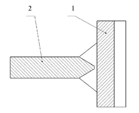
Fig. 5. Section of the welded joint of “fitting – plate” type:
1 — fitting; 2 — plate (shell)
The sample was tested on UDI-550 installation in a 3 % NaCl solution at rated voltages of 850 MPa. The test results showed that the number of cycles before the failure initiation doubled, and cracks appeared on the base metal. Photos of macrosections of the test results are shown in Figure 6.
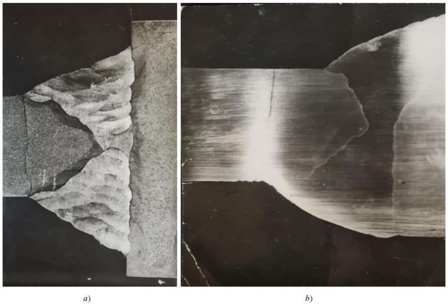
Fig. 6. Test results of “fitting – plate” welded joints in a corrosive environment:
a — fitting connection with symmetrical welds;
b — fitting connection with reinforcing weld on compressed fibers
(photo of the authors)
Analysis of the test samples allows us to establish that the durability of the fitting connection made by the proposed method turns out to be longer. In addition, due to the reinforcing influence of the weld metal from the side opposite to the action of the corrosive environment, the magnitude of the maximum tensile stresses in the most dangerous zone decreases; therefore, the resistance to the fracture initiation and development increases [16].
Research Results. Using the experience of designing individual installations and assemblies intended to test welded joints under biaxial bending conditions, scientists of DSTU and NRC “Kurchatov Institute” – CRISM “Prometey” have developed a series of installations designed to test sheet metal welded joints with a thickness of 20–100 mm with a yield strength up to 15 MPa under the biaxial bending conditions [17].
Discussion and Conclusions.
1. Leonov, V. P. Structural and Technological Strength of Steel for Marine Sstructures / V. P. Leonov, V. A. Malyshevskii // Metal Science and Heat Treatment. — 2001. — Vol. 43. — P. 444.
2. Ильин, А. В. Определение параметра трещиностойкости CTOD для металла сварных соединений судокорпусных сталей при низких климатических температурах / А. В. Ильин, В. П. Леонов, В. Ю. Филин // Научно-технический сборник Российского морского регистра судоходства. — 2009. — № 32. — С. 120–146.
3. Фетисова, Е. А. Особенности диффузионных процессов в сварных соединениях из разнородных сталей / Е. А. Фетисова, А. Г. Лупачёв // Вестник Белорусско-российского университета. — 2014. — № 3 (44). — С. 79–87. https://doi.org/10.53078/20778481_2014_3_79
4. Ilyin, A. V. On the Problem of Quantitative Service Life Assessment for High-Strength Steel Welded Structures under the Effect of Corrosion Medium / A. V. Ilyin, V. Y. Filin // Procedia Structural Integrity. — 2019. — Vol 14. — P. 964–977. https://doi.org/10.1016/j.prostr.2019.07.078
5. Kazuo Tateishi. Low Cycle Fatigue Strength of Butt-Welded Steel Joint by means of New Testing System with Image Technique / Kazuo Tateishi, Takeshi Hanji // International Journal of Fatigue. — 2004. — Vol. 26. — P. 1349–1356. https://doi.org/10.1016/j.ijfatigue.2004.03.016
6. Ильин, А. В. Определение конструктивной и технологической концентрации напряжений в сварных узлах при оценках усталостной прочности оболочечных конструкций / А. В. Ильин, К. Е. Садкин // Вопросы материаловедения. — 2012. — № 2 (70). — С. 161–176.
7. Дудка, Д. В. Критерий шейкообразования кристаллического анизотропного листового материала при двухосном растяжении / Д. В. Дудка, С. С. Яковлев, Ю. В. Бессмертная // Известия Тульского государственного университета. Технические науки. — 2010. — № 3. — С. 108–112.
8. Евдокимов, Д. В. Оценка предельной пластичности листового материала при двухосном растяжении / Д. В. Евдокимов // Известия Тульского государственного университета. Технические науки. — 2009. — № 2–2. — С. 83–88.
9. Дудка, Д. В. Локализация деформации кристаллического анизотропного листового материала при пластическом двухосном растяжении / Д. В. Дудка, С. С. Яковлев, Ю. В. Бессмертная // Известия Тульского государственного университета. Технические науки. — 2010. — № 3. — С. 85–88.
10. Зеньков, Е. В. Методика моделирования напряженного состояния деформируемых элементов транспортных систем в условиях двухосного растяжения / Е. В. Зеньков, Л. А. Багиева // Транспортная инфраструктура Сибирского региона. — 2016. — № 1. — С. 342–345.
11. Контроль остаточных напряжений в околошовной зоне сварного шва / В. А. Быченок, И. В. Беркутов, А. Л. Майоров [и др.] // Технология машиностроения. — 2019. — № 12. — С. 45–50.
12. Sushanta Kumar Panda. Experimental and Numerical Studies on the Forming Behavior of Tailor Welded Steel Sheets in Biaxial Stretch Forming / Sushanta Kumar Panda, D. Ravi Kumar // Materials & Design. — 2010. — Vol. 31. — P. 1365–1383. https://doi.org/10.1016/j.matdes.2009.08.046
13. Lyudmirskii, Y. G. Constructive and Technological Method of Increasing Durability of “Choke Connections” / Y G. Lyudmirskii, S. S. Assaulenko, S. O. Ageev // Journal of Physics: Conference Series. — 2021. — Vol. 2131. — Art. 042061. https://doi.org/10.1088/1742-6596/2131/4/042061
14. Measurement and Analysis of Welding Deformation and Residual Stress in CMT Welded Lap Joints of 1180 MPa Steel Sheets / Ritsu Nishimura, Ninshu Mab, Yong Liu [et al.] // Journal of Manufacturing Processes. — 2021. — Vol. 72. — P. 515–528. https://doi.org/10.1016/j.jmapro.2021.10.050
15. Evaluation of Fatigue Fracture Mechanism in a Flash Butt Welding Joint of a U75V Type Steel for Railroad Applications / Xiaohui Zhao, Yanjun Fan, Yu Liu [et al.] // Engineering Failure Analysis. — 2015. — Vol. 55. — P. 26–38. https://doi.org/10.1016/j.engfailanal.2015.05.001
16. Mechanical Responses of L450 Steel under Biaxial Loading in the Presence of the Stress Discontinuity / Shuai Wang, Cheng Hou, Bin Wang [et al.] // International Journal of Pressure Vessels and Piping. — 2022. — Vol. 198. — Art. 104662. https://doi.org/10.1016/j.ijpvp.2022.104662
17. Biaxial Testing System for Characterization of Mechanical and Rupture Properties of Small Samples / Andrea Corti, Tariq Shameen, Shivang Sharma [et al.] // HardwareX. — 2022. — Vol. 12. — Art. e00333. https://doi.org/10.1016/j.ohx.2022.e00333
1, Gagarin sq., Rostov-on-Don
1, Gagarin sq., Rostov-on-Don
10, Zhukovsky Highway, Volgodonsk, Rostov Region
Lyudmirsky Yu.G., Assaulenko S.S., Kramskoi A.V. Methods and Equipment for Experimental Evaluation of the Performance of Shell and Hull Structures. Advanced Engineering Research (Rostov-on-Don). 2022;22(3):252-260. https://doi.org/10.23947/2687-1653-2022-22-3-252-260


Advanced Engineering Research (Rostov-on-Don)
ISSN 2687-1653 (Online)
Contact with: Publisher / Editorial Office of the Journal
Publisher: Don State Technical University - DSTU, Rostov-on-Don, Russia - https://donstu.ru/en/
Editor-in-Chief: Alexey N. Beskopylny, Dr.Sci. (Eng.), Professor, Vice-Rector, Don State Technical University (Rostov-on-Don, Russia)
Don State Technical University
1, Gagarin Sq., Rostov-on-Don, 344003, Russia
tel.: +7 (863) 2738-372, e-mail: vestnik@donstu.ru
16+
Processing of personal data


