


Contents
Scroll to:
https://doi.org/10.23947/2687-1653-2022-22-4-346-352
Scroll to:
Introduction. One of the tasks of two-link manipulators of industrial robots that move the end-effector along complex trajectories (e.g., robot welder) is associated with the need for careful programming of their movement. For these purposes, manual programming methods or training methods are used. These methods are quite labor-intensive, and they require highly qualified service personnel. A possible solution to the problem of programming the manipulator movements is the simulation of motion with the calculation of angular coordinates. This can help simplify the geometric adaptation of the manipulator in the process of debugging the control program.
Therefore, this work aimed at calculating coordinates for programming the control system of a two-link manipulator operating in an angular coordinate system and moving the end-effector along a complex trajectory (e. g., when welding car bodies).
Materials and Methods. A two-link robot manipulator designed for cyclically repeating actions in an angular coordinate system was considered. The manipulator consisted of two rotating links: “arm” and “elbow”, which were fixed on the base. The base could rotate, which provided a third degree of freedom. This configuration increased the working area of the manipulator and minimized the area for its placement in production. The movement of the manipulator end-effector could be performed if the kinematics provided its positioning along three Cartesian and three angular coordinates. For software control of robots, including welding robots operating in an angular coordinate system and performing the movement of the end-effector along a complex trajectory, it was required to calculate the angular coordinates of the movement of the end-effector of a two-link articulated manipulator. The robot control system should determine the position of the tool in the angular coordinate system, converting it for user friendliness into x, y and z coordinates of the Cartesian coordinate system.
Results. The relations of angular and Cartesian coordinates have been obtained. They can be used for calculating when programming the control system of a two-link manipulator of an industrial robot and organizing the exchange of information between the user and the control system, as well as for checking the accuracy and debugging the movement of the end-effector of an industrial robot through feedback.
Discussion and Conclusion. The presented results can be used for software control of a welding robot operating in an angular coordinate system and performing a complex trajectory of the end-effector of a two-link articulated manipulator (gripper). A manipulator operating in an angular coordinate system can be used for contact spot welding when moving the end-effector along a complex trajectory using a positioning or contouring control system. These systems control the movement of the end-effector along a given trajectory with the help of technological commands.
Glushko S.P. Calculation of Angular Coordinates for the Control System of a Two-Link Industrial Robot Manipulator. Advanced Engineering Research (Rostov-on-Don). 2022;22(4):346-352. https://doi.org/10.23947/2687-1653-2022-22-4-346-352
Introduction. Industrial robots are used for automated control of the spatial orientation of tools and labor objects in various manufacturing processes1 [1–7]. An industrial robot, as a rule, includes a manipulator having several degrees of mobility, and a drive numerical control device. The manipulator is used to move a gripper or a tool along a given trajectory to specified points in the technological space2 [1–3].
When developing programs for controlling the movements of a gripper or an industrial robot tool along complex trajectories (e.g., for welding robots), training methods that are complex in organization and technical equipment are used.
To simplify the programming of the control system of a two-link manipulator of an industrial robot that moves the end-effector along a complex trajectory (e.g., when welding car bodies), you can use modeling of its movements with the calculation of angular coordinates. This will simplify the geometric adaptation of the manipulator and the process of developing and debugging its control programs.
The study is aimed at calculating angular coordinates for programming the operation of the control system for a two-link manipulator, which functions in an angular coordinate system and moves the end-effector along a complex trajectory.
Materials and Methods. In practice, four main types of manipulators, which operate in cylindrical, spherical, rectangular or angular coordinate systems, are used.
Figure 1 shows the working zone of the robot manipulator operating in an angular coordinate system. The manipulator consists of two rotating links — “shoulder” and “elbow”, which are fixed on the base. The base can rotate, which provides the third degree of freedom. This configuration increases the working zone of the manipulator and minimizes the area for its placement in production.
A manipulator operating in an angular coordinate system can be used for contact spot welding when moving the burner along a complex trajectory. To perform contact spot welding, robots with a positioning or contouring control system are most often used. These systems control the movement of the burner along a given trajectory at a specified orientation at a constant speed using technological commands.
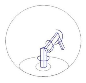
Fig. 1. Working zone of a manipulator operating in an angular coordinate system (the author's figure)
At that, the operation of the moving parts of the manipulator in the welding zone may be complicated by the influence of the heat generated. This problem is partially solved by the use of water cooling of burners with autonomous cooling devices. To completely eliminate this problem, you will need to additionally solve another task. Namely, a thermal problem with the simulation of a thermal process to determine and compensate for thermal expansion caused by heating by electric discharge or electric arc [8].
Research Results. To develop a control program for a robot that operates in an angular coordinate system (Fig. 1), it is required to calculate the angular coordinates of the movement of the end-effector of the manipulator (gripper) [1–4][6][7]. Figure 2 shows its scheme, consisting of two rods 1 and 2, which are connected by a ball-and-socket joint 3 and a flat joint 4. The whole structure is installed on the base 5. The manipulator rods have lengths 𝑙1 and 𝑙2. Joint 3 can rotate in the horizontal plane (angle α) and in the vertical plane (angle β). Joint 4 rotates in a vertical plane (angle γ).
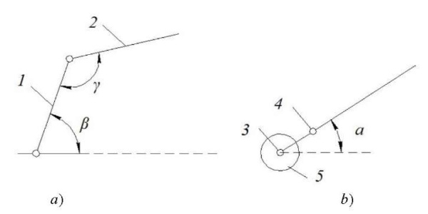
Fig. 2. Design of a two-link articulated manipulator:
a — main view; b — top view (the author's figure)
Figure 3 shows a diagram of a two-link articulated manipulator in the form of a hemisphere with radius 𝑅=𝑙1+𝑙2 and with a cut-out hemisphere with radius r, which is determined empirically when debugging the manipulator.
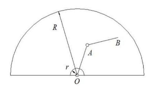
Fig. 3. Diagram of a two-link articulated manipulator (the author's figure)
The manipulator control system should set the position of the tool in the angular coordinate system and, for the convenience of the user, convert it into the parameters of the Cartesian coordinate system.
We take the base of the structure (point O) as the Cartesian coordinate system origin and arrange its axes as shown in Figure 4.
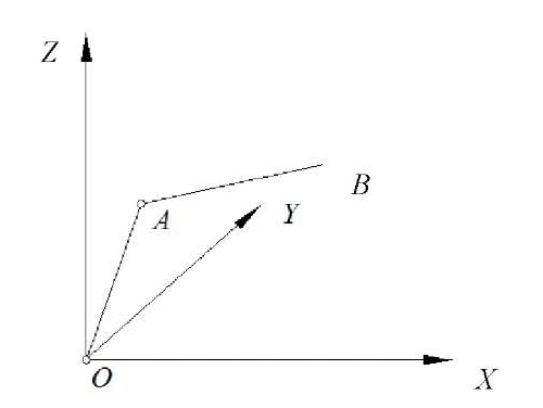
Fig. 4. Rectangular coordinate system centered at point O (the author's figure)
Angle α of the projection of the segment OB on plane XOY is shown in Figure 5.
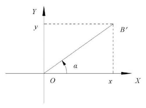
Fig. 5. Determination of the projection angle of segment OB on plane XOY (the author's figure)
Angle α is determined from the formula:
where x and y — coordinates of point B.
The sign “+” should be put if y is greater than or equal to zero, and the sign “–“, when y is less than zero.
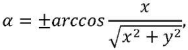
Angles of plane 𝑍𝑂𝐵´ 𝛽1, 𝛽2 and γ between the coordinate axes and levers 𝑙1 and 𝑙2 are shown in Figure 6.
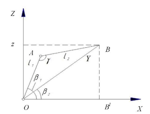
Fig. 6. Determination of angles 𝛽1, 𝛽2 and γ (the author's figure)
We find formulas for determining angles 𝛽1, 𝛽2 and γ using the cosine theorem:
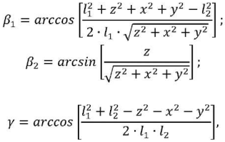
where x, y and z — coordinates of point B.
The ratios obtained can be used to calculate angular coordinates when developing control programs for a two-link manipulator of an industrial robot, solving problems of positioning or contouring control using feedback sensors for continuous monitoring and correction of intermediate points of the manipulator trajectory3 and drive motor control [5][6].
Dynamic systems of robots, including two-link manipulators operating in an angular coordinate system, are characterized by nonlinearities and are subject to disturbances. Therefore, to eliminate errors when reproducing the movement trajectory of the manipulator end-effector, the proposed calculation of angular coordinates can be supplemented with solutions using the following methods:
To control a two-link articulated manipulator with complex trajectories of its movement, it is promising to use the adaptive control with feedback sensors. Its signals are processed, and, based on the results of processing, decisions on further actions are made.
The structure of the proposed control system hardware (Fig. 7) includes drives of the manipulator links, sensors of the angular position of the manipulator links, temperature sensors of the burner mounting unit, a programmable logic controller that performs manipulator control functions.
Industrial robots use electric, hydraulic and pneumatic drives with translational and rotational motion. An electric drive, which is distinguished by a wide range of engine capacities, ease of speed control, and ease of automating control processes, is the most widespread in robotics.
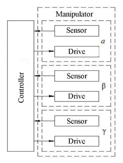
Fig. 7. Structure of hardware of the multilink articulated manipulator control system (the author's figure)
To control angular movements in multilink articulated mechanisms of manipulators with adaptive control systems performing complex trajectories, it is recommended to use angular position sensors — encoders. They provide measuring the movement parameters of the tool or the object being processed, the angles of their rotation, the direction of movement, the rotation speed of the shaft of the electric motor or gearbox, the angular position in relation to the zero mark, the direction of rotation.
Incremental and absolute encoders can be used in adaptive control systems. Incremental encoders are characterized by simplicity, reliability, and relatively low cost. Absolute encoders are more complicated and more expensive, but they provide determining the rotation angles of the axes of the links at any time immediately after turning on the power, and even in the stationary state of the links. Absolute encoders also enable to determine the rotation angles of the axes of the links when disconnecting and then restoring power, and do not require the device to return to its initial position. Moreover, the signals of absolute encoders are not affected by interference and vibration. In recent developments of adaptive control systems, inertial sensors with a number of improvements to compensate for errors in the manipulator movement control system have appeared [14].
Discussion and Conclusions. The calculation of angular coordinates for programming the operation of the control system of a two-link manipulator performing in an angular coordinate system and moving the working body along a complex trajectory was carried out. The relations of angular and Cartesian coordinates obtained in the work can be used to calculate and control angular displacements and to program control systems for two-link manipulators of industrial robots that move end-effectors along complex trajectories.
The calculation of angular coordinates for controlling a two-link manipulator of an industrial robot is presented in this paper as a solution to a geometric positioning problem. It can be used when modeling a similar manipulation device or when building a control system for such a manipulator and organizing the exchange of information between the user and the control system. It is also designed to check the accuracy and debug the movement of the end-effector of an industrial robot using feedback.
1. Kozyrev YuG. Promyshlennye roboty: osnovnye tipy i tekhnicheskie kharakteristiki. Moscow: KNORUS; 2015. 560 p. (in Russ.)
2. Ibid.
3. Glushko SP, Chastikov AP, Kornienko VG, et al. Software System for Testing and Debugging Control Programs for a Robotic Complex. Certificate of Software State Registration No. 2011611987, 2011. (In Russ,)
1. Горитов, А. Н. Программирование промышленных роботов без остановки производственного цикла / А. Н. Горитов // Доклады Томского государственного университета систем управления и радиоэлектроники. — 2009. — № 1 (19). — Ч. 1. — С. 61–64.
2. Горитов, А. Н. Синтез управляемых механических устройств с применением экспертной системы / А. Н. Горитов, И. В. Колотаев // Доклады Томского государственного университета систем управления и радиоэлектроники. — 2009. — № 1 (19). — Ч. 1. — С. 72–76.
3. Горитов, А. Н. Сглаживание траектории перемещения рабочего инструмента робота манипулятора / А. Н. Горитов, С. М. Алферов // Известия Томского политехнического университета. — 2006. — Т. 309, № 8. — С. 176—179.
4. Горитов, А. Н. Моделирование адаптивных мехатронных систем / А. Н. Горитов, А. М. Кориков. — Томск : В-Спектр, 2007. — 350 с.
5. Босинзон, М. А. Автоматизированные мехатронные модули линейных и вращательных перемещений металлообрабатывающих станков / М. А. Босинсон // Приводная техника. — 2002. — № 1. — С. 10–19.
6. Букреев, В. Г. Алгоритм планирования траектории движения следящего многокоординатного электропривода / В. Г. Букреев, Н. В. Гусев // Известия высших учебных заведений. Электромеханика. — 2003. — № 3. — С. 16–20.
7. Гусев, Н. В. Алгоритмическое обеспечение систем управления следящими электроприводами / Н. В. Гусев // Научно-технический и учебно-образовательный журнал: Известия высших учебных заведений. Электромеханика. — 2006. — № 3. — С. 57–60.
8. Глушко, С. П. Моделирование теплового процесса центробежной биметаллизации внутренней поверхности втулок / С. П. Глушко, Д. Л. Поправка, Н. С. Абрамов // Сварочное производство. — 2009. — № 6. — С. 30–35.
9. Uglev, V. A. Automated Education: Tendency for Scientific Approaches Convergence / V. A. Uglev, D. I. Suchinin // In: Proc. 2nd International Conference on Applied Social Science Research (ICASSR2 014). — 2014. — P. 20–23. doi: 10.2991/icassr-14.2014.6
10. Xing-Gang Yan. Nonlinear Robust Fault Reconstruction and Estimation Using Sliding Mode Observers / Xing-Gang Yan, Ch. Edwards // Automatica. — 2007. — Vol. 43. — P. 1605–1614. doi: 10.1016/j.automatica.2007.02.008
11. Jing He. Fault Reconstruction Based on Sliding Mode Observer for Nonlinear Systems / Jing He, Changfan Zhang // Mathematical Problems in Engineering. — 2012. — Vol. 2012. — Art. 451863. doi: 10.1155/2012/451843
12. A Direct Approach to Solving Trajectory Planning Problems Using Genetic Algorithms with Dynamics in Complex Environments / F. J. Abu-Dakka, F. J. Valero, J. L. Suñer, V. A. Mata // Robotica. — 2015. — Vol. 33. — P. 669–683. doi: 10.1017/S0263574714000393
13. On-Line Path Planning with Collision Avoidance for Coordinate- Controlled Robotic Manipulators / T. Kivelä, J. Mattila, J. Puura, S. Launis // In: Proc. ASME/BATH 2017 Symposium on Fluid Power and Motion Control. — 2017. — P. 1–10. doi: 10.1115/FPMC2017-4297
14. Titterton, D. H. Strapdown Inertial Navigation Technology, 2nd ed. / D. H. Titterton, J. L. Weston // MPG Books Ltd.: Bodmin, Cornwall, UK; 2004. — 558 p.
Sergey P. Glushko
2, Moskovskaya St.
Krasnodar
Glushko S.P. Calculation of Angular Coordinates for the Control System of a Two-Link Industrial Robot Manipulator. Advanced Engineering Research (Rostov-on-Don). 2022;22(4):346-352. https://doi.org/10.23947/2687-1653-2022-22-4-346-352


Advanced Engineering Research (Rostov-on-Don)
ISSN 2687-1653 (Online)
Contact with: Publisher / Editorial Office of the Journal
Publisher: Don State Technical University - DSTU, Rostov-on-Don, Russia - https://donstu.ru/en/
Editor-in-Chief: Alexey N. Beskopylny, Dr.Sci. (Eng.), Professor, Vice-Rector, Don State Technical University (Rostov-on-Don, Russia)
Don State Technical University
1, Gagarin Sq., Rostov-on-Don, 344003, Russia
tel.: +7 (863) 2738-372, e-mail: vestnik@donstu.ru
16+
Processing of personal data


