


Contents
Scroll to:
https://doi.org/10.23947/2687-1653-2023-23-3-269-282
Scroll to:
Introduction. The performance and reliability of gerotor hydraulic machines depend on the geometry of the cycloidal gearing profile. The existing methods of calculating and optimizing the profile parameters are cumbersome, multicriteria and difficult for practical application. Therefore, the problem of creating the methodology for calculating the parameters of the gerotor machine profile suitable for engineering calculations at the stage of conceptual design is a challenge. In this regard, the objective of this work was to modernize the methodology for designing the geometry of the profiles of the end section of hypocycloidal gears used in gerotor hydraulic machines, and to analyze the possibilities of their optimization during preliminary design. In the course of the study, the Mathcad computer mathematics system was used; numerical experiments were carried out to study the influence of geometric profile parameters on the performance and operability of the gerotor hydraulic machine, based on the data obtained and analyzed; recommendations for the design of optimal profiles of the end section of gerotor hydraulic machines were developed.
Materials and Methods. Materials included known methods of profile parameters calculation, based on application of classical formulas of hypocycloidal equidistant used for outlining profiles of teeth of working elements of gerotor machines. The basic research method was modeling the gerotor machine profile using Mathcad computer mathematics system. Calculated data were obtained for the selected ranges of varying parameters, processed through the univariate regression analysis.
Results. An algorithm for analyzing the tooth profile smoothness was developed. Two target parameters were defined: the cross-sectional area of the end profile, which affects the productivity; the smallest reduced radius of contact that determines operability of the working body. A technique for calculating the target parameters at the early stage of design was proposed. A number of optimal values of profile parameters according to the criteria of productivity and operability of gerotor machine was obtained. The dependences providing the optimum values of profile parameters at the stage of designing were constructed.
Discussion and Conclusion. The developed methodology makes it possible to obtain an assessment of the performance and operability of the gerotor hydraulic machine at the design stage of the working body. The research results can be used in mechanical engineering when designing gerotor hydraulic machines in order to improve their technical and operational characteristics.
Kireev S.O., Lebedev A.R., Korchagina M.V. Optimization of Geometric Characteristics of Cycloidal Profiles of Gerotor Hydraulic Machines. Advanced Engineering Research (Rostov-on-Don). 2023;23(3):269-282. https://doi.org/10.23947/2687-1653-2023-23-3-269-282
Introduction. Gerotor hydraulic machines are increasingly being used in the construction and operation of oil and gas wells. The reason is their structural and operational advantages, the primary of which are low delivery unevenness for pumps or torque for motors, compact overall dimensions.
In the scientific literature, a large place is occupied by studies devoted to the operation of gerotor hydraulic machines. The strong geometric effects of the rotor profile on the performance and reliability of screw gerotor hydraulic machines were noted by D. and F. Baldenko [1]. The basic unit of such a machine is a multithread screw gerotor mechanism — a cylindrical planetary gear train of internal gearing, consisting of a stator and a rotor, with a difference in the number of teeth equal to one. The stator profile in the end section contacts the rotor profile, forming closed platforms. The authors also analyzed the technology of manufacturing gears.
R. Iyer, V. Jatti and others investigated the feasibility of mathematical models in the design of screw pumps [2]. They also presented the results of modeling various sizes of twin-screw pumps when pumping water, a mixture of water and air. Hong-Seok Park and Xuan-Phuong Dang proposed a CAD model optimization process using the results of CAE modeling and Mathcad calculations [3]. Other authors (A. Lebedev. S. Kireev. M. Korchagina. S. Vlaskin. A. Efimov) noted in their publications the effectiveness of designing various objects and processes based on parametrization and subsequent optimization of the design according to one or more target parameters [4–6].
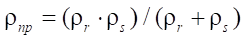
In their work, F.D. Baldenko and Yang Yao have emphasized that the open area does not depend on the relative position of the rotor and stator profiles and determines the pump performance. They analyzed the effect of dimensionless geometric profile parameters on the open area [7].
Jie Chen, He Liu, Fengshan Wang, Guocheng Shi, Gang Cao and Hengan Wu developed a finite element model of the working body of a screw pump with a surface drive for the oil and gas industry [8]. Based on the results of modeling and experimental tests, they concluded that the gaps in the coupling and the thickness of the stator were the two key factors affecting the optimized target parameter — the volumetric efficiency of the pump.
New data were obtained by J. Gamboa, A. Olivet and S.H. Espin when modeling the working body of a multilobe screw pump [9]. These authors determined a significant relationship between the sliding clearance area and the pressure drop associated with the mechanical properties of the stator material.
Yang Yao and F. Baldenko investigated the effect of dimensionless coefficients of the end profile of a gerotor hydraulic machine on the characteristics of cycloid engagement, which provided optimization based on geometric and kinematic criteria [10]. I.A. Lyagov, F.D. Baldenk, A.V. Lyagov, V.U. Yamaliev and A.A. Lyagova proposed a methodology for selecting the optimal configuration of power sections when designing sectional downhole motors, noting the urgency of the problem of reducing the overall parameters of the screw pump length [11].
Yu.A. Korotaev, A.N. Alpatov, A.V. Sobolev and others have come to the conclusion that the most effective is mesh profiling from the initial contour of the rail outlined by the equidistant shortened cycloid [12]. With regard to the profiles obtained from the equidistant of an ordinary hypocycloid, the authors pointed out their major drawback: they were built as special and did not provide for tension in the engagement. Yu.A. Korotaev and D.A. Goldobin drew attention to the problem associated with the need to increase the performance of screw pumps, and the resulting unacceptable rigidity conditions under the production of stators and rotors [13].
A.F. Minikaev, V.A. Pronin, D.V. Zhignovskaya, Yu.L. Kuznetsov, F.D. Baldenko, A.E. Kovalenok developed a methodology for studying the stress-strain state of the stator during contact interaction with the rotor of a screw working body of a hydraulic machine using CAE modeling. They have stated that the classical Hertz theory of contact interaction cannot be applied to determine contact stresses in the rotor and stator due to a number of features: change in the curvature of the contacting surfaces of the rotor and stator; different thickness of the elastic lining along the circumference of the housing; presence of preload in a pair; complex planetary motion of the rotor, accompanied by a combination of friction rolling and sliding; displacement of the radial force vector relative to the normal at the point of contact.
Summing up the review of scientific publications on the design of a gerotor hydraulic machine, it should be noted that most researchers in this field strive to improve the efficiency of this machine by increasing the open area and reducing the overall dimensions of the working body. Optimal results were achieved by applying and varying the coefficients of off-centroidness, tooth shape, relative sliding speed, rail displacement, etc. Calculation methods were cumbersome, they were difficult to apply in practice. End profiles were built, as a rule, on the basis of shortened hypocycloids, which caused problems with providing kinematic accuracy of movement, contact interaction of the rotor and stator. Some authors (Yu.A. Korotaev, A.N. Alpatov, A.V. Sobolev, et al.) pointed out the impossibility of creating tension in the case of using an ordinary hypocycloid, but tension could be created through changing the equidistant distance of the rotor and stator profiles.
Materials and Methods. To obtain profiles of the rotor and stator in the end section of the working body of the gerotor hydraulic machine, we specify the following set of initial parameters (Fig. 1):
 — profile contour radius, which determines the diameter of circle С1, describing the profile of the stator (mm). In fact, this parameter assigns the radial dimension of the gerotor machine, which is particularly important in the oil and gas industry when the projected object needs to be placed, e.g., in the trunk of the production well column;
 — number of rotor teeth;
 — radius of the roller, which determines the distance of the equidistant line of the rotor and stator profiles relative to the corresponding hypocycloids (mm);
Recall the principle of formation of hypocycloidal engagement profiles, which consists in the fact that inside circle  (base circle of the stator hypocycloid), circle
  (base circle of the rotor hypocycloid) rolls without sliding. The center of circle
 ![]() is always at distance e (eccentricity) from the center of circle
is always at distance e (eccentricity) from the center of circle 
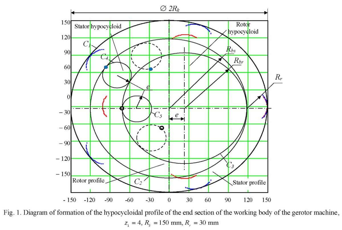
Inside circle  circle
  (generating circle of the rotor hypocycloid), one point of which forms the rotor hypocycloid, rolls without sliding. Inside circle
  circle
  (generating circle of the stator hypocycloid), one point of which forms the stator hypocycloid, rolls without sliding. Note that the radii of circles
  and
and  are equal to eccentricity е. The rotor and stator profiles are formed as equidistant lines deposited at distance
  from the corresponding hypocycloids.
In this setting, the rotor and stator profiles provide an ideal contact under eccentric rotation of the rotor. When required to provide tension/clearance in the engagement, the equidistant distance  for the rotor profile should be changed by D.
Let us move on to the mathematical description of the method of forming the profiles of the end section of the rotor and stator. The number of stator teeth is equal to
 (1)
(1)
The radius of the base circle of the stator hypocycloid  is determined from the condition (Fig. 1):
 (2)
(2)
We determine eccentricity e of the transmission from the condition that the length of circle  is equal to integer
  of the lengths of generating circle
  with radius е:
then,
 (3)
(3)
Note that for  (Moineau mechanism) according to other formulas:
 (4)
(4)
The radius of the base circle of the rotor hypocycloid  is equal to (Fig. 1):
 (5)
(5)
We introduce a function to determine the radius of the base circle of the rotor or stator, fulfilling conditions (2)
and (5):
 (6)
(6)
Parametric formulas of the hypocycloid of the rotor and stator in the Cartesian coordinate system XOY:
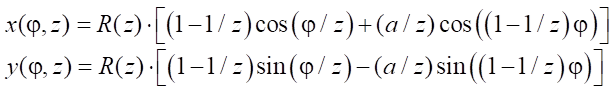 . (7)
. (7)
where z — number of branches of the hypocycloid of rotor  or stator
  a — velocity factor of the hypocycloid. In the case of an ordinary hypocycloid in theory,
  However, in practical calculations using computer mathematics systems (Mathcad. MATHLAB) at
  difficulties arise with calculating equidistant profiles of the rotor and stator. Therefore, in the model, we assume
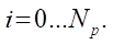
  which is quite justified to achieve our goals; j — rotation angle of the radius vector drawn from the origin to each point of the hypocycloid. If the hypocycloid must be constructed from
  points, then
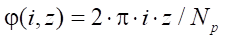 .
.  (8)
(8)
The profiles of the rotor and stator are determined from the well-known equidistant trajectory formulas relative to the hypocycloids of the rotor or stator at distance Rr taking into account the tension in the coupling D.
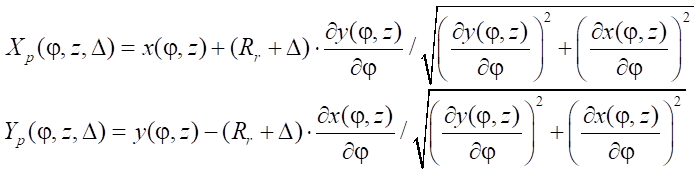 . (9)
. (9)
During transmission operation, the center of the rotor moves along a circle with radius e and rotates by angle α=0…2p. At the same time, all points of the rotor make an additional rotation by angle y, determined by the function
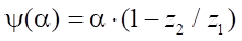 . (10)
The rotor rotation model is described by parametric coordinate transformation functions when moving and rotating an object:
 . (11)
In expression (11), a conditional function is applied that zeroes the movement along Y axis in the case of rectilinear movement of the rotor in the stator cavity at 
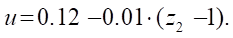
The experience of using this technique has shown that the equidistant profiles of the rotor and stator with an increase in the equidistant distance or radius of the roller  can lose smoothness. This occurs at the points of transition from the equidistant circle to the equidistant hypocycloid. Figure 2 shows the problem of loss of smoothness of the stator profile line in the vicinity of ±1 mm from the transition point of equidistant lines.
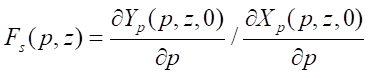
In mathematics, the formula for the function smoothness criterion given in parametric form is known. For the stator profile, such a function has the form
 , (12)
where 
p — angle of the radius vector of the stator profile point.
It should be noted that function  behaves unstable in the entire range
  , and it is quite difficult to find any features of its behavior at the transition point of equidistant lines of interest to us. Therefore, the behavior of function
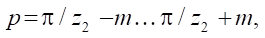
  was studied only in the vicinity of the transition point when the angular parameter changes
 (13)
(13)
where m — angle of deviation from the angle of the radius vector of the transition point.
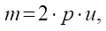 (14)
(14)
where u — part of the angular sector of the stator profile to study smoothness in the vicinity of the transition point. Value u (for 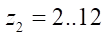 ) is determined from the empirical formula
 (15)
(15)
Figure 2 shows that with an increase in the radius of the roller in the vicinity of the transition point of equidistant lines, the stator profile turns from smooth to self-intersecting. The behavior of function  also changes, and when the self-intersection effect of the profile appears, a loop occurs (Fig. 2 c).
This effect is taken as a basis for the stator profile smoothness control algorithm proposed by the authors of the article (Fig. 3). It should be noted that, judging by numerous measurements, if the stator smoothness criterion is met, then the smoothness of the rotor profile does not need to be checked, since it is built on a hypocycloid with a smaller value of the radius of the base circle.
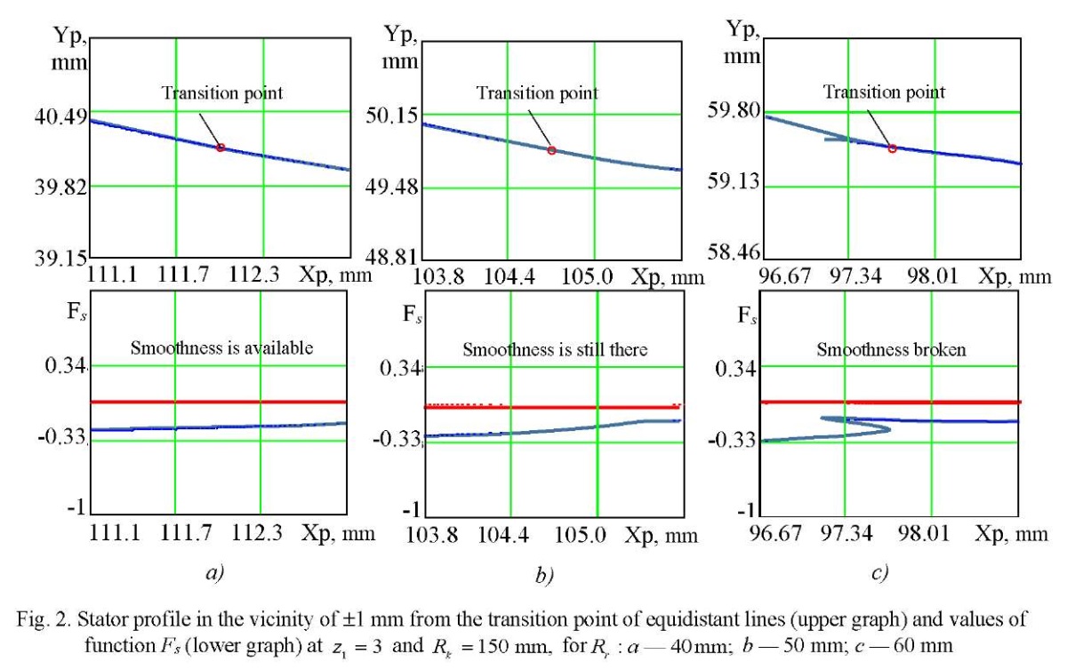
Control of the stator profile smoothness should always be carried out when designing the geometry of the end section of the gerotor machine. In order to study the parameter of the maximum radius of roller  , below which the smoothness of the curve was not violated, the authors conducted a series of numerical experiments where various values of the contour radius
  and the numbers of rotor teeth
  were specified.
The first target parameter of this study is the open area of the working body S. This parameter is included in the formula for feeding the gerotor machine, and it determines its performance. With the available parametric functions describing the profiles of the rotor and stator, the task of determining S is reduced to calculating the difference in the areas of the parametric curves of stator  and rotor
  (9). The formula for the area of the parametric curve is known from mathematics; therefore, in the authors' methodology, it looks like this:
 (16)
(16)
The second target parameter of the study is the reduced radius  of curvature at the contact interaction of the rotor and the stator. Recall that according to Hertz theory, when two cylindrical surfaces come into contact, the reduced radius is calculated, which is in the denominator in the contact stress formula. Consequently, the magnitude of the contact stresses, along with the physical and mechanical parameters of the materials of the contacting surfaces, has the largest value at the lowest value of the reduced radius
  determined from the formula:
 . (17)
where  — radius of the equidistant circle of the rotor, equal to parameter
 — radius of the stator profile curve.
Note that if  then the numerator in formula (17) always grows faster than the denominator; therefore, the smallest value
  is completely determined by the parameter of the smallest radius of the stator
In the end section of the working body of the gerotor machine, at any rotation angle of the rotor, continuous contact of its equidistant circle and a complex curve of the stator profile is made. Based on the results of observations of the contact interaction dynamics, it can be concluded that the greatest stresses occur at the transition points of the equidistant hypocycloids in the equidistant circumference of the stator profile. Consequently, the smallest radius of the stator profile line  is also located in the transition zone of equidistant lines and determined by the formula known from mathematics:
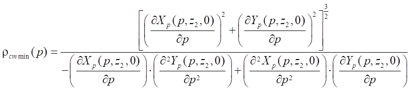 . (18)
where  angular parameter of the stator profile point at the junction of equidistant lines. In case of loss of smoothness of the stator line, parameter
  tends to zero.
The technique described above was implemented in the Mathcad system of mathematical calculations. When performing calculations, the hypocycloid velocity factor a = 0.99,  40,000.
At the first stage of research. it was planned to study the maximum radius of roller  at which the stator profile line smoothness criterion G was zero. Variable parameters — contour radius
  (100, 150, 200 mm) and the number of rotor teeth
  (from 1 to 7). Calculations were performed with a sequential increase in parameter
  from 5 mm until the smoothness criterion G was trigged. The investigated parameter
  was fixed with an accuracy of 1 mm.
At the second stage, a series of calculations were carried out to study the effect of the roller radius  (from 5 mm to
  ), the number of rotor teeth
  (from 2 to 7) and the contour radius
  (100, 150, 200 mm) on the open area S and the minimum reduced contact radius
The described method of calculating the profile geometry of the end section of the working body of the gerotor machine can be implemented in any other programming system or in a computer mathematics system.
Research Results. The data of numerical experiments to determine the parameter of the maximum radius of roller  at which the stator profile line smoothness is preserved, are shown in Table 1.
Table 1
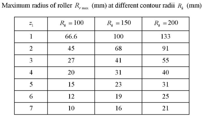
Based on the data in Table 1, graphs were constructed (Fig. 4 a). It can be seen that the estimated parameter  grows proportionally with increasing contour radius
  We introduce into consideration the relative parameter
 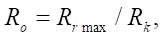 whose graph is presented in Figure 4 b.
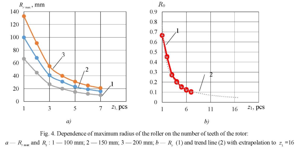
The empirical formula from which it is possible to determine the maximum allowable radius of roller  has the form:
 (19)
(19)
At  = 15,
= 15,  = 150 mm,
  = 0.0517 mm,
  7.76 mm, the profile smoothness is achieved at Rr = 7.5 mm. At
  = 10,
= 10,  = 200 mm,
  = 0.0775 mm,
  15.5 mm, the profile smoothness is achieved at Rr = 15.5 mm. Thus, we can conclude about the satisfactory accuracy of empirical formula (19) for predicting the maximum allowable parameter Rr max.
It should be noted that formula (19) was obtained at the values of the velocity factor a = 0.99. A decrease in a causes the smoothness of the profile with a more significant increase in parameter  However, the shape of the cycloidal engagement tooth changes, and the conditions of contact interaction between the rotor and the stator are violated, specifically, in those places where the rotor should touch the stator with the sides of the teeth. Calculations show that at
  and
and  38 mm, the smoothness criterion is at the limit of feasibility. Though at
  and
and  38 mm, good smoothness of the stator profile is achieved, but the kinematic contact of the parts of the working body of the machine is disrupted, which can be restored only by a special selection of the values of the hypocycloid parameters of the rotor and stator. Therefore, the study of the influence of the velocity factor on parameter
  is beyond the scope of this research.
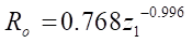
Table 2 presents the data of calculations of the target parameters of the studies for the number of rotor teeth  = 3 at different values of contour radii. The obtained values of the open area S and the minimum reduced contact radius
  in the last two columns of Table 2 are given in a dimensionless form for ease of analysis.
Table 2
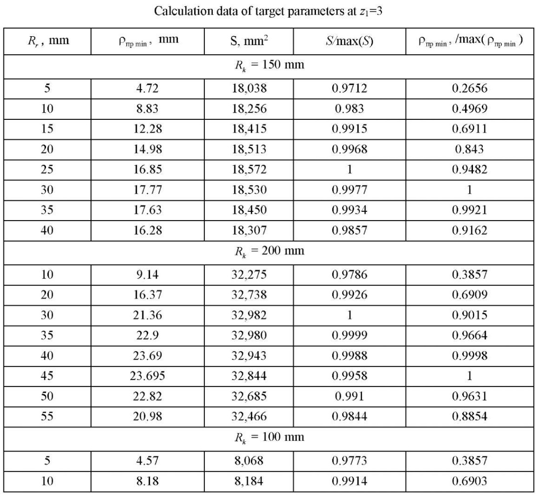
Figure 5 shows graphs of variation in the target parameters of studies at  =3. It is easily seen on them that with an increase in the radius of roller
  there is a slight change in the open area S and a sufficiently strong change in the reduced contact radius, whose maximum value falls on a fairly narrow range
  . This is of the greatest interest to the designer, since in this case, the contact stresses are minimal. Calculations for other values
  (from 2 to 7) showed approximately the same qualitative picture as in Figure 5.
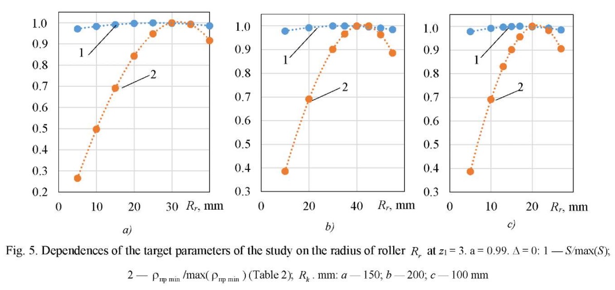
Table 3 shows the calculation data of the optimal radii of rollers Rr opt for various parameters  and
and  . As a result of the analysis, it turned out that parameters Rr opt and
  for one
  change almost the same. Therefore, if you enter the parameter of the relative optimal radius of the roller
 (20)
(20)
then, with the help of a single-factor dependence of  -type, it is possible to determine the optimal radius of roller
  at the preliminary stage of designing the working body of the gerotor machine.
As a result of similar reasoning, for parameters S and  given in Table 3, dimensionless parameters of the relative reduced radius of contact
  and relative open area
  were also introduced (Table 3):
 (21)
(21)
New relative values are also presented in Table 3.
Table 3
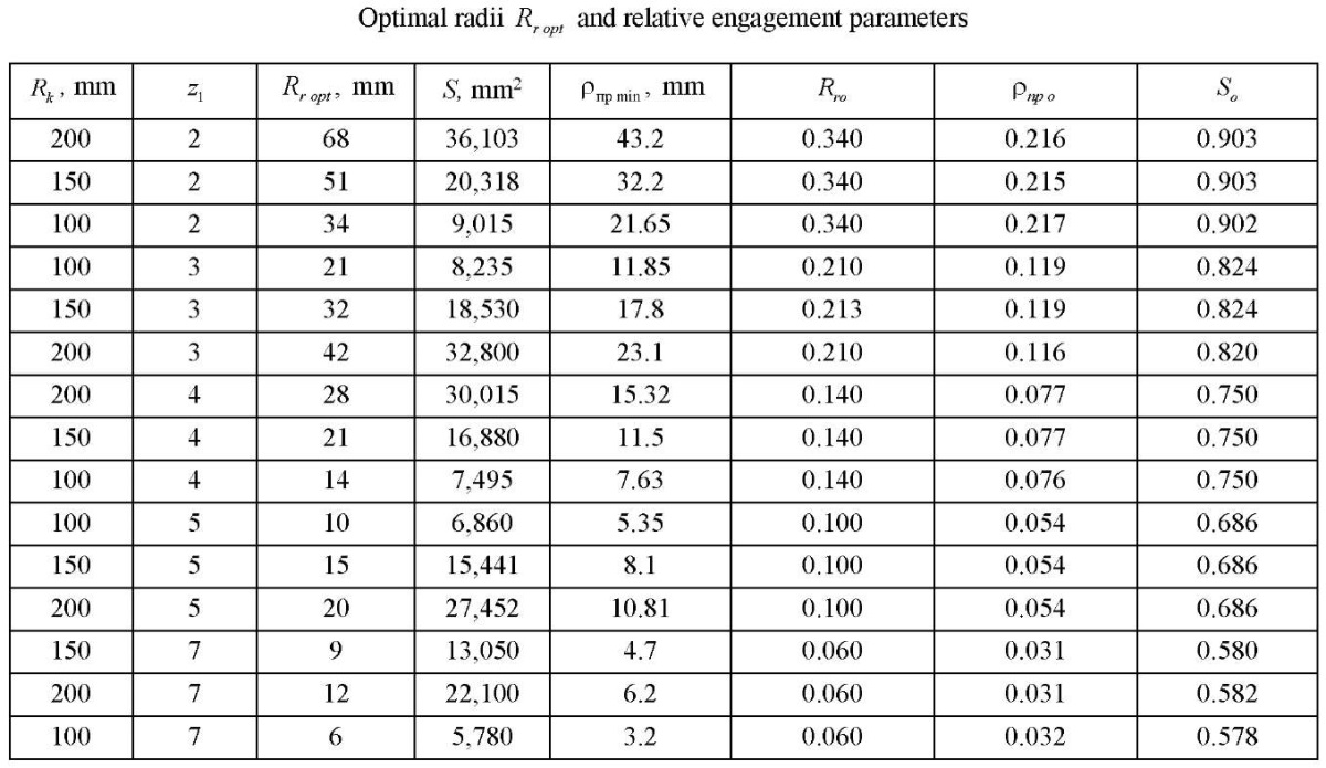
It should be noted that all newly introduced relative values with a high degree of confidence obey approximating formulas that include one factor — the number of rotor teeth  .
.
The formula for the relative optimal radius of roller  has the form
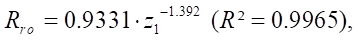 (22)
(22)
where  — value of the approximation accuracy.
The formula for the relative reduced contact radius  has the form
 (23)
(23)
The formula of the relative open area So has the form
 (24)
(24)
Let us consider an example of the application of the results obtained in the design of the geometry of the end section profile of the gerotor machine. We specify the following set of initial data: contour radius  120 mm, number of rotor teeth
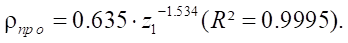
  4, tension in the coupling D=0 mm (empirical formulas are obtained at zero tension). The relative optimal radius of roller
  according to formula (22):
Absolute value of the roller radius 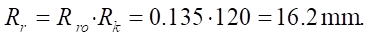
Relative reduced contact radius  from formula (23):
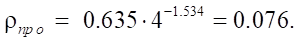
Absolute value of the minimum reduced contact radius
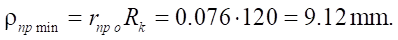
Relative open area  from formula (24):
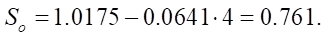
Absolute value of the open area

Mathcad calculations give the following values:
As can be seen in this example, empirical formulas accurately predict the basic parameters of the geometry of the end section of the gerotor machine.
Discussion and Conclusion. The conducted research was aimed at solving the problem of improving the working bodies of gerotor hydraulic machines. It sufficiently corresponds to the works of domestic and foreign authors [10–15]. The key difference is that when constructing the rotor and stator profiles, ideal hypocycloids are used, providing the greatest kinematic accuracy of movement and contact interaction of the engagement elements. It was proposed to solve the well-known problem of providing tension in the coupling with respect to the difference in the parameters of the roller radius. A special algorithm was developed to control the smoothness of the profiles [12]. The optimal geometry of the profile, as in [10], was proposed to be determined on the basis of the maximum open area of the working body of the gerotor machine. But at the same time, the reduced contact radius should also have the largest value, as a guarantee of the lowest contact stresses. In this study, based on a large number of calculations using a purpose-built Mathcad program, in the range of rotor teeth  from 2 to 7 and contour diameter
  from 100 to 200 mm, optimal values of the equidistant hypocycloid distance, or roller radii
  at which the best combination of the reduced contact radius and the open area of the working body of the gerotor was achieved. It turned out that the introduction of relative values of the radius of the roller, the open area, and the reduced contact radius provided obtaining absolute values of the same magnitudes for any contour radius within the established ranges using simple empirical dependences at an early stage of design.
The developed technique makes it possible to evaluate the performance and operability of the gerotor machine at the design stage of the rotor and stator profiles. In the future, similar studies can be carried out for epicycloid and mixed engagements in gerotor hydraulic machines.
The research results can be used in mechanical engineering under the design of gerotor hydraulic machines to improve their operating characteristics.
1. Baldenko DF, Baldenko FD. Single-Screw Hydraulic Machines in the Oil and Gas Industry: Fields of Application and Development Prospects. Petroleum & Petrochemical Engineering Journal. 2019;3(5):000207. https://doi.org/10.23880/ppej-16000207
2. Ramakrishnan Balaji Iyer, Jatti VK, Yeshpal Yadav, Anurag Verma, Jaimin Desai, Dewan CP. Design Optimization of CAD Model. Materials Today: Proceedings. 2017;4(8):7357−7364. https://doi.org/10.1016/j.matpr.2017.07.065
3. Hong-Seok Park, Xuan-Phuong Dang. Structural Optimization Based on CAD–CAE Integration and Metamodeling Techniques. Computer-Aided Design. 2010;42(10):889–902. https://doi.org/10.1016/j.cad.2010.06.003
4. Lebedev A, Kireev S, Korchagina M, Lubinec V. Improvement of Design of Device for Production of Cycloidal Pinion Gear. In: M Shamtsyan, M Pasetti, A Beskopylny (eds). Robotics, Machinery and Engineering Technology for Precision Agriculture. Smart Innovation, Systems and Technologies. Vol. 247. P. 223−236. Singapore: Springer; 2022. https://link.springer.com/chapter/10.1007/978-981-16-3844-2_24
5. Korchagina M, Lebedev A, Kireev S, Vlaskin S. Model of Hole Mandrel Process in Tubular Workpieces. In book: A. Guda (ed) Networked Control Systems for Connected and Automated Vehicles. Vol. 509. P. 1541 Springer; 2022. https://doi.org/10.1007/978-3-031-11058-0_156
6. Lebedev A, Kireev S, Korchagina M, Efimov A. Optimization of Structure Parameters of Semi-Trailer-Tank for Hydraulic Fracturing of Formation. In book: A. Guda (ed) Networked Control Systems for Connected and Automated Vehicles. Vol. 510. Cham: Springer; 2023. https://doi.org/10.1007/978-3-031-11051-1_178
7. Baldenko FD, Yang Yao. The Study of the Chambers Area of the Working Bodies of Single-Screw Hydraulic Machines. Drilling and Oil Magazine. 2020;(6):24–29. https://burneft.ru/archive/issues/2020-06/24
8. Jie Chen, He Liu, Fengshan Wang, Guocheng Shi, Gang Cao, Hengan Wu. Numerical Prediction on Volumetric Efficiency of Progressive Cavity Pump with Fluid-Solid Interaction Model. Journal of Petroleum Science and Engineering. 2013;109:12–17. https://doi.org/10.1016/j.petrol.2013.08.019
9. Gamboa J, Olivet A, Espin S. New Approach for Modeling Progressive Cavity Pumps Performance. Journal of Petroleum Technology. 2003;56(5):51–53. https://doi.org/10.2118/84137-MS
10. Yang Yao, Baldenko F. Optimization of Cycloidal Gearing Geometric Parameters of Positive Displacement Motors. Equipment and Technologies for Oil and Gas Complex. 2021;(6):22−26. https://doi.org/10.33285/1999-6934-2021-6(126)-22-26
11. Lyagov I, Baldenko F, Lyagov A, Yamaliev V, Lyagova A. Methodology for Calculating Technical Efficiency of Power Sections in Small-Sized Screw Downhole Motors for the “Perfobur” System. Journal of Mining Institute. 2019;240:694−700. https://doi.org/10.31897/pmi.2019.6.694
12. Korotaev YuA, Alpatov AN, Sobolev AV, Myalitsin NYu. Investigation of the Systematic Error of Gerotor Mechanism Action Profiled from the Initial Rack Contour. Izvestiya Tula State University. 2017;8(1):112–120.
13. Korotaev YuA, Goldobin DA. Designing and Calculation Peculiarities of the Multiple-Thread Screw-Type Gerotor Machines of the Multiphase Pumps. Izvestiya Tula State University. 2016;8(2):175–182.
14. Minikaev AF, Pronin VA, Zhignovskaya DV, Kuznetsov YuL. The Use of Computer Modelling for the Development of the Working Bodies’ Profiles for Screw Single-Rotor Compressor. Journal of International Academy of Refrigeration. 2018;(1):61−66. https://doi.org/10.17586/1606-4313-2018-17-1-61-66
15. Baldenko FD, Kovalenok AE. Komp'yuternoe modelirovanie kontaktnogo vzaimodeistviya rabochikh organov odnovintovykh gidravlicheskikh mashin. Neftegaz Territory. 2014;10:18–27. (In Russ.)
Sergey O. Kireev, Dr.Sci. (Eng.), Professor, Head of the Oil and Gas Complex Machinery and Equipment Department
1, Gagarin sq., Rostov-on-Don, 344003
Alexey R. Lebedev, Cand.Sci. (Eng.), Associate Professor of the Oil and Gas Complex Machinery and Equipment Department
1, Gagarin sq., Rostov-on-Don, 344003
Marina V. Korchagina, Cand.Sci. (Eng.), Associate Professor of the Oil and Gas Complex Machinery and Equipment Department
1, Gagarin sq., Rostov-on-Don, 344003
Kireev S.O., Lebedev A.R., Korchagina M.V. Optimization of Geometric Characteristics of Cycloidal Profiles of Gerotor Hydraulic Machines. Advanced Engineering Research (Rostov-on-Don). 2023;23(3):269-282. https://doi.org/10.23947/2687-1653-2023-23-3-269-282


Advanced Engineering Research (Rostov-on-Don)
ISSN 2687-1653 (Online)
Contact with: Publisher / Editorial Office of the Journal
Publisher: Don State Technical University - DSTU, Rostov-on-Don, Russia - https://donstu.ru/en/
Editor-in-Chief: Alexey N. Beskopylny, Dr.Sci. (Eng.), Professor, Vice-Rector, Don State Technical University (Rostov-on-Don, Russia)
Don State Technical University
1, Gagarin Sq., Rostov-on-Don, 344003, Russia
tel.: +7 (863) 2738-372, e-mail: vestnik@donstu.ru
16+
Processing of personal data


