


Contents
Scroll to:
https://doi.org/10.23947/2687-1653-2024-24-2-159-169
EDN: YAIWEZ
Scroll to:
Introduction. Published studies on the rigidity of consoles under load focus on the issues of their deformation and destruction. Calculations of the inertia moment, fundamentally important characteristic of the strength of the rod, are described. However, the problem of significant time consumption for such calculations has not been solved. The presented study meets the lack. The objective of the work is to describe a new rapid method for analytical calculation of the shear stress distribution in the section of the console corresponding to the action of an external applied force. For the first time, tangential stresses are considered, and examples of calculating the inertia moment for two non-standard sections of the console are given in this context.
Materials and Methods. To develop a new method, the console was presented as a pack of plates oriented parallel to the vector of external force. The source calculations were based on the scheme of a console beam with a dedicated plate. The deformation of the rod elements was modeled taking into account the effect of a uniform shear stress field in the plate section. To validate the simplified calculation of the inertia moment of the sections, schemes of a square, ellipse, triangle, hexagon, six-pointed star, and a figured cross were used. Analytical and mathematical research methods were applied, specifically, the Huygens–Steiner theorem.
Results. A rapid valid method for calculating the inertia moment of the cross section of the console under loading has been developed. Its difference is the rejection of calculations for each section, taking into account the shape and other features. For any shape of the section, the beam is represented as a bundle of infinitely thin plates, their inertia moments are integrated, and a well-known solution for deflection of a thin plate is used. The method allows us to unambiguously show the distribution of tangential stresses at the end of the console, providing a given deflection, and tangential stresses are used for such solutions for the first time. Their profiles are obtained depending on the direction of the external applied force. Formulas for the inertia moments of complex sections — a six-pointed star and a figured cross — are derived for the first time. Each section is correlated with the stress distribution curve and its maximum value. This data is visualized in the form of diagrams. It is found that the inertia moment and the rigidity of the console do not change when the external applied force is rotated by 30° for a star-shaped section and by 45° for a square and a figured cross. In general, the tangent field depends on the geometry and on the orientation of the section relative to the external applied force.
Discussion and Conclusion. The proposed simplified approach to calculating the inertia moment of the cross sections of the consoles makes it possible to uniquely determine the field of tangential stresses at the end, which provides the appropriate value of the external applied force for the given deflection. Engineers and mechanics can use the results of the presented work in the calculations and modeling of deformation of rod structural elements.
Deryugin E.E. Simplified Calculation of the Inertia Moment of the Cross Section of the Console under Loading. Advanced Engineering Research (Rostov-on-Don). 2024;24(2):159-169. https://doi.org/10.23947/2687-1653-2024-24-2-159-169. EDN: YAIWEZ
Introduction. Numerous building structures contain elements in the form of rods, which undergo elastic deformations during manufacture or operation [1]. The bending strength of a rod or beam determines the bearing capacity of the structure [2]. The ability of a beam to elastic deformation is characterized by stiffness, defined as the ratio of load P to the elastic deflection of the beam λe : mx = P / λe [3]. As a rule, under laboratory conditions, stiffness is checked on a console beam. One end of it is embedded in a rigid base, and an external force, directed perpendicular to the axis of the beam, acts on the other one [4]. Modeling and calculations of deformation and fracture characteristics of rods, as a rule, are associated with solving the problem of deflection of a console beam, or console, under the action of an external applied force [5]. At the same time, there are no publications on simple and valid methods for determining the inertia moments of complex sections relative to the action of an external applied force. The solution to this problem is described in the presented article.
This work is aimed at the creation of a valid, rapid method for calculating the inertia moments of complex console sections under the action of an external applied force. The new approach provides analytical determination of the shear stress distribution in the section corresponding to the action of an external applied force. It should be noted that earlier, tangential stresses were not taken into account in such calculations. In addition, for the first time, examples of calculating the moment of inertia for complex figured sections are given.
Materials and Methods. In a number of works on the resistance of materials, e.g., in [6], a universal formula is given for calculating the elastic deflection of console λe. According to this formula, the rigidity of the console is:
 (1)
(1)
where E — Young's modulus; L — length of the console; Ix — inertia moment of the cross-section of the beam relative to x-axis, passing through the center of gravity of the section perpendicular to the applied force P.
It follows from equation (1) that a fundamentally important characteristic of the console is the inertia moment of section Ix, whose value depends on the geometry of the cross-section of the beam and the direction of x-axis [7]. It should be emphasized that in equation (1), inertia moment Ix refers to x-axis, which is perpendicular to the direction of the external applied force P. Specifically, the inertia moment of rectangular section a×b relative to the axis of symmetry x is equal to [8]:
 (2)
(2)
Here, a — thickness of the console, b — its width. Force P is directed parallel to side b of the rectangle.
Substituting (2) into (1), we obtain the well-known equation for the deflection of a rectangular console [9]:

The cross sections of console beams, or consoles, are different. Figure 1 shows a simple example of a square section console under the action of external force P, directed along the diagonal of a square.
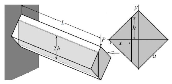
Fig. 1. Diagram of a console beam with a dedicated plate
The inertia moment of the section relative to x-axis is called the sum, or integral, of the products of elemental areas ds = dxdy by the squares of distances y of the areas to x-axis:  [10]. The integrand function is virtually the inertia moment of the elemental area dxdy relative to x-axis.
The console can be represented as a pack of extremely thin plates with thickness dx and length L, oriented parallel to the force vector P. Under the action of P, all plates bend by the same amount λe. With a given orientation of the console section, a separate plate is not affected by deformation of the rest of the volume. Then, the inertia moment of the section of the console as a whole will be determined by the integral sum of the inertia moments of the sections of all the plates in the pack.
The projection of the plate onto the plane of the console cross section is a rectangular strip with thickness dx and half-length h (Fig. 1). The inertia moment of the section of a separate plate can be considered as the inertia moment of the console of rectangular section 2h×dx. By definition, the equation of type (2) is applicable to each plate in a pack, where a = dx and b = 2h. According to this expression, the inertia moment of the strip is dIx = 2h3(x)dx/3. Thus, the inertia moment of the console section can be determined through integrating the inertia moments of elementary strips rather than elemental areas:
 (3)
(3)
where x varies from A to B.
The condition for the orientation of the plane of the plates parallel to the vector of the external applied force is important, since it provides a unique association of the elastic deflection of console λe with the distribution of tangential stresses in the cross section of the console. All the plates in the pack bend by the same value λe. according to (1), dIx = 2h3(x)dx/3. This means that elementary force dP = 3leEdIx / L3 = 2leEh3(x)dx / L3 is required for a plate with thickness dx. This force corresponds to the action of a uniform shear stress field in the plate section ds(x) = 2h(x)dx:
 (4)
(4)
It can be seen from (4) that the value of voltage λe in the coordinate system xy does not depend on coordinate y.
Equation (4) is convenient to be used when modeling the deformation of rod structural elements.
Integral (3) determines the inertia moment of section Ic relative to x-axis, passing through the center of gravity of the section. In the case of asymmetric and complex sections, it is convenient to first find the inertia moment of the section or part of the section relative to the axis that does not pass through the center of gravity of the section. Then, you need to move on to the inertia moment of section Ic relative to the axis that passes through the center of gravity of the section. It is known that the inertia moment of the section repeats the properties of the inertia moment of a solid and obeys the Huygens–Steiner theorem [11]. The inertia moment of section Ix relative to arbitrary x-axis is equal to the sum of the inertia moment of this section Iс relative to the axis passing through the center of gravity of the section parallel to x-axis, and the product of the cross-sectional area S by the square of distance a between the axes: Ix = Iс + a2S. Therefore, in the general case, we can write:
 (5)
(5)
If x-axis passes through the center of gravity of the section, then distance a = 0 and equation (5) turns into (3).
Research Results. To create a simple, fast, valid calculation method, we abandon calculations for each section, taking into account its shape and other features. This approach was implemented for the first time in the framework of this research. No matter how complex the cross-section is, it is quite sufficient to use a well-known solution for deflecting a thin plate, present the beam as a pack of infinitely thin plates, and integrate their inertia moments. In addition, the method allows us to unambiguously show the distribution of tangential stresses at the end of the console, providing a given deflection. It should be emphasized that tangential stresses are considered in this context for the first time.
Short-Cut Calculation of the Inertia Moment of Simple Sections. To validate the proposed method, we consider the known sections of simple geometry. Next, instead of the expression “inertia moment of the cross section of the console”, we use the term “inertia moment”. We assume that the external applied force is always directed perpendicular to x-axis, relative to which the inertia moment of the section is determined.
Square. Equation (2) is obtained under the condition that the vector of force applied to the end of the console is perpendicular to side a of the rectangle. For b = a, we obtain the inertia moment of the square section Ic = a4/12.
Using the proposed method, we find the inertia moment of the square relative to x-axis, which is parallel not to the side, but to the diagonal of the square (Fig. 2 a).
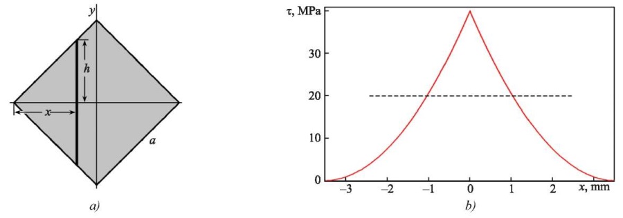
Fig. 2. Cross-section diagram in the form of a square:
a — cross-section; b — voltage distribution τ along x-axis
The half-length of the strip in Figure 1 is equal to h = x. From equation (3), we find:

It can be seen that turning x-axis by 45° does not change the inertia moment of the square section. Consequently, when the external applied force is rotated by 45°, the rigidity of the console does not change either (1).
Substituting x in place of h (4), we obtain a shear stress distribution in the section of the square console corresponding to deflection λe:

Figure 2 b shows distribution τ (x) along the diagonal of the square at λe = 2 mm and a = 5 mm. According to (1), the action of the shear stress τ (x) on the end of the steel console (E = 200 GPa) with length L = 50 mm corresponds to the action of an external applied force P = 0.25Eλe a4/L3 = 500 N. Maximum voltage τmax = 40 MPa is observed on the vertical diagonal of the square. Under the deviating from the diagonal, voltage τ decreases sharply to zero. As a result, a sharp peak is formed in the system τ (x).
Voltage τ depends only on variable x; therefore, according to the graph in Figure 2 b, it is possible to determine value τ at any point of the square.
Obviously, when the force is oriented perpendicular to the sides of the square, τ = P/a2 = 20 MPa (Fig. 2 b, dotted line). As can be seen, stress distribution τ(x) in the cross section corresponding to external force P significantly depends on its direction.
Ellipse. Figure 3 a shows a diagram of an ellipse with semi-axes a and b. The origin of coordinates is in the center of the ellipse.
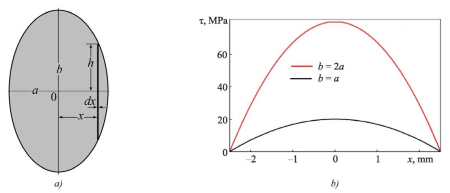
Fig. 3. Section diagram in the form of ellipse with semi-axes a and b:
a — ellipse; b — distribution τ along semi-axis a.
1 — a = b, 2 — b = 2a, a = 2.5 mm
It follows from the canonical equation of ellipse [12] that the strip highlighted in Figure 3 has half-length h = b(a2 – x2)1/2/a. Substituting this value in (3) and integrating from –a to +a, we obtain the inertia moment of the elliptical section:
 (6)
(6)
At a = b = r, we derive the inertia moment of the circular section: πr4/4, where r — radius of the circle.
Substituting value h corresponding to the ellipse in (4), we obtain the following distribution of shear stress in the section of the elliptical console:

Figure 3 b shows distribution τ(x) along semi-axis a = 2.5 mm at λe = 2 mm, E = 200 GPa and L = 50 mm. When comparing it to distribution τ(x)in Figure 2 b, for a square, a significant influence of the geometry of the console section on the stress distribution is obvious. In the case of the elliptical section, there is no sharp peak on curve τ(x). Maximum voltage τmax is observed along semi-axis b. Taking into account the requirement λe = const, it can be said about a rapid growth of voltage τmax with an increase in ratio b/a. When half-axis b is doubled, τmax increases by 4 times (Fig. 3 b).
Triangle. Consider the section in the form of an isosceles triangle (Fig. 4). x-axis is directed along the altitude of the triangle (Fig. 4 a). At distance x from the base of the triangle, the half-length of the strip is equal to h = b (a – x)/2a.
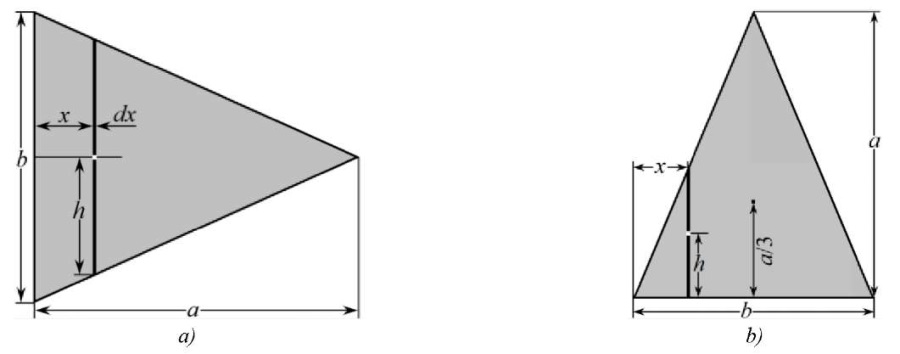
Fig. 4. Section diagram in the form of isosceles triangle:
a — x-axis, force is directed parallel to the base;
b — force is directed perpendicular to the base
Integrating expression (4) over x from 0 to a determines the following value of the inertia moment:
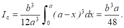 (7)
(7)
Consider the case when x-axis passes through the center of gravity and is parallel to the base of the triangle (Fig. 4 b).
The strip at distance x from the left corner of the triangle has half-length  (Fig. 4 b). The center of gravity of the strip is located at distance h from the base of the triangle (Fig. 4 b). Therefore, according to the Huygens–Steiner theorem for the cross section, the inertia moment of the strip relative to the base of the triangle is:

Integrating the resulting expression over variable x from –b/2 to b/2 determines the inertia moment of the triangle relative to the base:
 (8)
(8)
The center of gravity of the triangle is located at distance a/3 from the base. According to the Huygens–Steiner theorem [13], the inertia moment of a triangle relative to its own center of gravity is less than (8) by:

where S = ab/2 — area of triangle.
In this manner, the inertia moment of the triangle relative to its own center of gravity is equal to:
 (9)
(9)
The result obtained corresponds exactly to the tabular value of the inertia moment of the section relative to the axis through the center of gravity parallel to the base of the triangle.
Figure 5 shows the shear stress distributions in the triangular section at λe = 2 mm for cases where the deflection force is directed along the base (a) and along the altitude of the triangle (b).

Fig. 5. Distributions τ in the triangular section:
a — force is directed along the base;
b — force is directed along the altitude of the triangle
When the triangle is oriented as in Figure 4 a, voltage τ(x) decreases gradually from τmax at the base to 0 at the apex (Fig. 5 a). With the orientation of the triangle as in Figure 4 b, distribution τ(x) (Fig. 5 b) is similar to the distribution for a square section when the force is oriented along the diagonal (Fig. 2 b).
Regular hexagon. Figure 6 shows two orientation of the hexagon relative to x-axis: parallel (a) and perpendicular (b) to its diagonal.
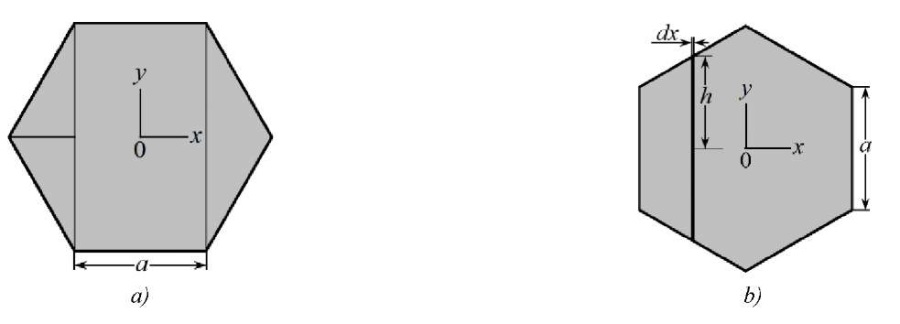
Fig. 6. Regular hexagon:
a — diagonal is perpendicular to the force vector;
b — diagonal is parallel to the force vector
The section of the hexagon in Figure 6 a consists of the following:
Let us find the inertia moments of the specified parts of the section by (2) for the rectangle and by (7) for triangles. For the rectangle in equation (2), b = a√3; therefore, its inertia moment is Ix1 = √3a4/4. For triangular parts in equation (7), the base is b = a√3, and the altitude is a/2. Consequently, the inertia moment of the hexagon is:
 (10)
(10)
If the applied force is directed along the diagonal of the hexagon (Fig. 6 b), then the half-length of the strip is equal to a/2 – x/√3. Having made the appropriate substitutions in (4), we obtain:
 (11)
(11)
Comparing (10) and (11), we make sure that the rotation of the hexagon by 30° does not affect its inertia moment relative to x-axis.
Consider the case of the hexagon orientation as in Figure 6 a. At λ = 2 mm and Е = 200 GPa in the range from –a/2 to +a/2, voltage τ(x) is constant and equal to τmax = 15 MPa (Fig. 7 a). Under the same conditions and orientation of the hexagon as in Figure 6 b, distribution τ (x) is similar to the distribution for a square section (Fig. 2 b). However, here, τmax = 20 MPa and τmin = 5 MPa (Fig. 7 b).
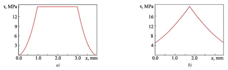
Fig. 7. Distribution τ(x) in the section of the regular hexagon:
a — diagonal is perpendicular to the force vector;
b — diagonal is parallel to the force vector
Examples of Simplified Calculation of the Inertia Moment of Complex Sections
Six-pointed star. Using the proposed method, we calculate the inertia moment of a non-standard section in the form of a regular 6-pointed star with side a. To determine the inertia moment relative to the minor diagonal of the star, we use the diagram in Figure 8 a. Let us highlight three zones in the diagram: zone I with width a/2, zone II for the rest of the half-figure, and the adjacent auxiliary zone III in the form of a triangle.
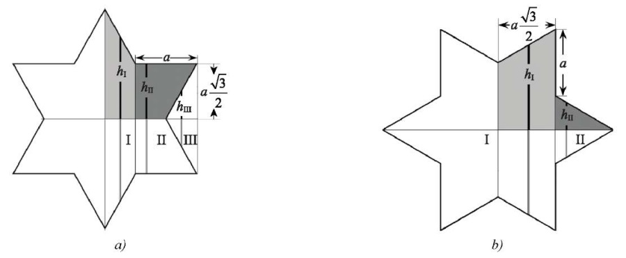
Fig. 8. On calculating the inertia moment of the six-pointed star
relative to a — minor diagonal; b — major diagonal
Half-length of the strip in zone I at distance x from the diagonal is hI = √3(a – x). Using expression (3), for two zones I in Figure 6 a, we obtain the inertia moment:

The inertia moment of zone II is equal to the inertia moment of a rectangle with height a√3 and width a without the inertia moment of triangle III. The half-length of the strip in the rectangle is equal to hII = a √3/2. From equation (3), we find the inertia moment of the rectangle:

The half-length of the strip in the triangle is equal to hIII = x√3. According to (4), the inertia moment of the triangle is:

Hence, the inertia moment of zone II is equal to:

The doubled sum of the inertia moments of zones I and II determine the inertia moment of the 6-pointed star:
 (12)
(12)
To determine the inertia moment of the star relative to the major diagonal, we use the diagram in Figure 8 b, where two zones are highlighted. The half-length of the strip in zone I is hI = a + x/√3, in zone II — hII = a/2 – x/√3. From (3), the inertia moments of zones I (IxI = a465√3/96) and II (IxII = a4√3/96) are calculated. It is seen that the doubled sum of the inertia moments of zones I and II corresponds exactly to equation (12). Therefore, the inertia moment of the 6-pointed star relative to the major and minor diagonals is the same.
Figure 9 a shows the shear stress distribution in the section of the 6-pointed star corresponding to λ = 2 mm and the orientation of the external applied force according to Figure 8 a. Along the vertical axis of the star, the voltage takes on maximum value τmax = 37.5 MPa. With distance from the axis to the right, τ drops quickly to the level τ = 9.375 MPa and remains constant in the range 2 ≤ x ≤ 4 mm. Then, τ drops to zero. With distance away from the axis to the left, τ changes similarly.
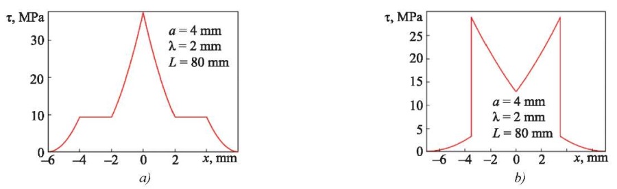
Fig. 9. Distributions τ in the hex-shaped section:
a — force is directed along the major diagonal;
b — force is directed along the minor diagonal
When the star rotates by 30°, voltage distribution τ changes significantly, acquiring the outlines of a dovetail (Fig. 9 b). Two peaks are observed with value τmax = 28.12 MPa. The distribution pattern is symmetrical. However, with distance from the axis of symmetry, the voltage first increases from 12.5 to 28.12 MPa, and then drops to 3.125 MPa. In this regard, two peaks are observed on dependence τ(x). Further on, the voltage decreases rapidly to zero.
Figured cross. Consider a solution for the inertia moment of a non-standard section in the form of a figured cross (Fig. 10), each side of which is the fourth part of the circle of radius R. The distance between the apices of the figure is R√2. We first find the inertia moment of the cross relative to the major diagonal (Fig. 10 a).
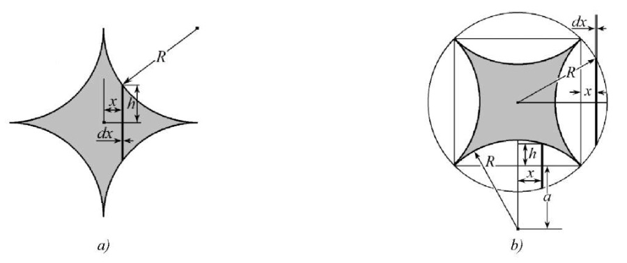
Fig. 10. Figured cross:
a — force is directed along the diagonal of the cross;
b — force is directed at an angle of 45° to the diagonal of the cross
Half-length of strip h in Figure 10 a is equal to:

Taking into account the symmetry and using equation (3), we obtain the following value of the inertia moment of the section of the figured cross:
 (13)
(13)
We determine the inertia moment of the cross when it is rotated by 45° relative to x-axis (Fig. 10 b).
Figured cross fits into the circle of radius R. Figure 10 b shows that there are four figures in the form of an oval with sharp corners around the cross. To determine the inertia moment of the cross, it is sufficient to subtract the inertia moments of the four ovals from the inertia moment of the circle.
It follows from (6) that the inertia moment of the circle is equal to:

We determine the inertia moments of the ovals relative to the center of gravity of the cross.
The inertia moment of the oval on the right is equal to the inertia moment of the oval on the left. Half-height of the strip at the oval on the left is:

We take into account equation (3), as well as the symmetry of these parts and their location. By integrating from 0 to R – R/√2, the following value of the inertia moment of these two parts is obtained:
 (14)
(14)
The centers of gravity of the ovals above and below the circle are located at distance a = R/ from the center of gravity of the whole figure. The area of these two parts is equal to S = R2(π – 2).
By (4), we calculate the moment of inertia of this pair:

Value h in (3), according to Figure 10 b, (oval at the bottom of the circle) is equal to  Therefore, for a pair of ovals at the top and bottom of the circle, the inertia moment relative to their own centers of gravity can be recorded as:
 (15)
(15)
We determine the resulting inertia moment of the figured cross. To do this, we subtract the inertia moments of the four ovals from inertia moment (13) of the circle:

Comparing the result obtained to result (13), we can see that the inertia moment of this cruciform section of the console does not change when x-axis is rotated by 45°.
Figure 11 a shows the distribution of shear stress in the cross section of the figured cross, corresponding to λ = 2 mm, and the action of an external applied force along the axis of the cross (Fig. 10 a). A sharp voltage peak is observed on the vertical axis of the cross, where τmax = 80.0 MPa.
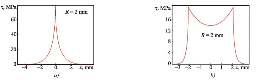
Fig. 11. Distributions τ in the section of the figured cross:
a — force is directed along the diagonal of the cross,
b — force is directed at an angle of 45° to the diagonal of the cross
When the cross is rotated relative to the applied force by 45°, voltage distribution τ changes significantly. As the axis of symmetry deviates, voltage first gradually increases from τ = 13.73 MPa to τ max = 20.32 MPa. Then, voltage τ drops sharply to zero. Therefore, two symmetrical peaks (Fig. 11 b) are observed in distribution τ at a distance of 2 mm from the axis of symmetry.
Discussion and Conclusion. The proposed simplified calculation method provides for the rapid determination of the inertia moments of complex cross sections of the console. In this case, the shear stress field in the sample section corresponding to the action of an external applied force is uniquely determined. In addition, it is shown that the stress distribution in the section qualitatively and quantitatively depends on the orientation of the section relative to the direction of the external applied force.
To validate the method, the inertia moments were calculated not only for known sections of simple geometry (which showed the absolute identity of the calculated and published results in the literature), but also for two new complex sections in the form of a regular six-pointed star and a figured cross. It is shown that the rigidity of the console does not change when an external force applied perpendicular to the axis of symmetry is rotated by 30° for a section in the form of a 6-pointed star, and by 45° — for a square and a figured cross. The method and the solutions obtained can be used by engineers and mechanics in modeling and calculating strength and stiffness of rod structural elements.
1. Ching Francis DK, Onouye B, Zuberbuhler D. Building Structures Illustrated: Patterns, Systems, and Design. 2nd ed. Hoboken, NJ: John Wiley & Sons; 2014. 352 p. URL: https://zlib.pub/book/building-structures-illustrated-1rgfde22jln8 (accessed: 22.02.2024).
2. Hallebrand E, Jakobsson W. Structural Design of High-Rise Buildings. Lund: Media-Tryck LU; 2016. 142 p.
3. Amany D, Pasini A. Material and Shape Selection for Stiff Beams under Non-Uniform Flexure. Materials and Design. 2009;30(4):1110–1117. http://doi.org/10.1016/j.matdes.2008.06.029
4. Pilkey WD. Formulas for Stress, Strain, and Structural Matrices. Hoboken, NJ: John Wiley & Sons; 2005. 1536 p.
5. Gaidzhurov PP, Saveleva NA. Application of the Double Approximation Method for Constructing Stiffness Matrices of Volumetric Finite Elements. Advanced Engineering Research (Rostov-on-Don). 2023;23(4):365–375. https://doi.org/10.23947/2687-1653-2023-23-4-365-375
6. Murakami Y. Theory of Elasticity and Stress Concentration. Hoboken, NJ: John Wiley & Sons; 2016. 480 p. URL: https://www.wiley.com/en-us/Theory+of+Elasticity+and+Stress+Concentration-p-9781119274100 (accessed: 22.02.2024).
7. Bechtel FK. Estimating Local Compliance in a Beam from Bending Measurements. Part I. Computing “Span Function”. Wood and Fiber Science. 2007;39(2):250–259. URL: https://wfs.swst.org/index.php/wfs/article/view/1344/1344 (accessed: 22.02.2024).
8. Bhattacharjya RK. Engineering Mechanics. New Delhi: Oxford University Press; 2009. 832 p.
9. Damkilde L. Stress and Stiffness Analysis of Beam Sections. Copenhagen: Technical University of Denmark; 2000. 36 p.
10. Zhernakov VS. Material Resistance — Mechanics of Materials and Structures. UFA: Ufa State Aviation Technical University; 2000. 36 p. (In Russ.).
11. Kleppner D, Kolenkow R. An Introduction to Mechanics. 2nd ed. Cambridge: Cambridge University Press; 2014. 566 p.
12. Pan'zhenskii VI, Surina OP, Sorokina MV. Plane Analytic Geometry. Penza: Penza State University; 2020. 120 p. (In Russ.).
13. Brown RG. Introductory Physics I. Elementary Mechanics. Durham: Duke University Physics Department; 2013. 661 p.
Evgeny E. Deryugin, Dr.Sci. (Phys.-Math.), Professor, Leading Researcher of the Laboratory of Physical Mesomechanics and Non-Destructive Testing Methods
2/4, Akademicheskii Ave., Tomsk, 634055
Deryugin E.E. Simplified Calculation of the Inertia Moment of the Cross Section of the Console under Loading. Advanced Engineering Research (Rostov-on-Don). 2024;24(2):159-169. https://doi.org/10.23947/2687-1653-2024-24-2-159-169. EDN: YAIWEZ


Advanced Engineering Research (Rostov-on-Don)
ISSN 2687-1653 (Online)
Contact with: Publisher / Editorial Office of the Journal
Publisher: Don State Technical University - DSTU, Rostov-on-Don, Russia - https://donstu.ru/en/
Editor-in-Chief: Alexey N. Beskopylny, Dr.Sci. (Eng.), Professor, Vice-Rector, Don State Technical University (Rostov-on-Don, Russia)
Don State Technical University
1, Gagarin Sq., Rostov-on-Don, 344003, Russia
tel.: +7 (863) 2738-372, e-mail: vestnik@donstu.ru
16+
Processing of personal data


