


Contents
Scroll to:
https://doi.org/10.23947/2687-1653-2024-24-4-316-327
EDN: TSFHRJ
Scroll to:
Introduction. When applying hydraulic fracturing technology to increase the efficiency of formation fluids, high-pressure pumps with a crosshead drive assembly are used. The major problem in the operation of these pumps is the wear of the crosshead guides. The crosshead is a flat sliding friction pair, leading to wear of the plunger seals and a decrease in the basic pump performance indicators. To solve this problem, it was previously proposed to use new materials and antifriction coatings, original designs of friction units, etc. However, a detailed description and solution to the problem under consideration has not been found in the literature at present. The objective of this study is to determine, under maximum load, the influence of the unit design, process temperature and pressure in the lubrication system on the values of the parameters that provide for the hydrostatic mode for a flat thrust bearing in a crosshead-guide unit of a high-pressure plunger pump.
Materials and Methods. The parameters were determined by the simulation technique using modal analysis applicable in the case of high dynamic loads acting on the studied unit. The calculation of the hydrodynamic parameters of the lubricating layer was based on the combination of the Reynolds model and the Stokes model in numerical modeling. The study was conducted using a calculation model representing a section of a plunger pump, considered as “flexible bodies” model, in the field of gravity forces. The mathematical dependences of the parameters under consideration were presented in the form of regression equations obtained from the results of a numerical experiment.
Results. The maximum load on the lower crosshead guide was determined, for which further hydrodynamic studies were conducted. Factors influencing the process were studied — gaps filled with lubricant (depending on the design of the unit), temperature, and pressure in the lubrication system. Mathematical dependences of the influence of the considered factors on the values of the parameters determining the establishment of the hydrostatic mode were obtained.
Discussion and Conclusion. The obtained mathematical models show the degree and influence of the factors under consideration on the studied parameters of the hydrostatic lubrication mode of the unit — the force acting on the crosshead from the lubricating layer, and the mass flow rate of the lubricant at the outlet of the system. It is found that the greatest influence is exerted by the change in the volume of gaps filled with lubricant, the mass flow rate of lubricant at the entrance to the system, which simulates the increase in pressure in the lubrication system of the friction unit. The results obtained do not contradict the conclusions reached in works on similar topics, and can be used in further research.
Korchagina M.V., Stepanov V.N., Kireev S.O., Lebedev A.R. Investigation of Parameters Influencing the Establishment of Hydrostatic Mode in the Crosshead-Guide Assembly of High-Pressure Plunger Pump. Advanced Engineering Research (Rostov-on-Don). 2024;24(4):316-327. https://doi.org/10.23947/2687-1653-2024-24-4-316-327. EDN: TSFHRJ
Introduction. In recent years, hydraulic fracturing (HF) and massive hydraulic fracturing technologies have been widely used for the efficient extraction of formation fluids. The unique properties of the materials used in hydraulic fracturing provide a short production cycle and a small investment compared to the conventional extraction. Energy companies often refuse to participate in long-term projects with an unstable and unknown future. However, the flexible manufacturing process of HF technology avoids the uncertainty that is typical of mineral commodity markets that focus on the short-term [1]. The HF technology requires the use of high-pressure pumps (105 and 138 MPa) with high flow rates (9,000 l/min) and a capacity of more than 5,000 kW. The elastic seals of piston pumps do not withstand the required loads and do not allow adjusting the tightening forces of the seal pack. This has led to the use of plunger pumps under these conditions. With such capacities, the load on the pump rod (plunger) can reach more than 140 tons. With a pressure in the hydraulic part of the pump of 105 (138) MPa (using highly aggressive and highly abrasive media as working fluids), sealing packs operate under extremely difficult conditions, the modeling of which is the subject of papers [2][3]. To relieve the radial load on the plunger seals, a crosshead arrangement of the drive part is used, when the entire radial load from the connecting rod group is taken up by the crosshead (slider). In high-power pumps (3,500–5,000 kW), the load on the crosshead in the contact zone with the guide can reach tens of tons, which can cause the breakdown of the oil film in the contact zone.
The crosshead, moving along the guides, provides radial fixation of the plunger, taking up significant alternate loads from the connecting rod and the pressure of the pump working medium. The crosshead is made of high-alloy steels and experiences significant loads, unlike the guides, which, in addition to centering, must provide a minimum of friction costs. Wear of the crosshead guides causes wear of the plunger seals and a decrease in pressure and feed. The crosshead guides are a composite structure — a rigid base made of carbon steel and antifriction liners. To reduce wear of the liners, liquid lubricant is supplied to the contact area under pressure by means of an oil hydraulic system. Uniform distribution of lubricant in the contact area is provided by oil distribution grooves on the crosshead. However, these measures ultimately provide a rather short service life (800–1,000 hours) of the crosshead group, which entails a reduction in the service life of the entire pump. This determines the urgency of studying the conditions for the occurrence of a hydrostatic mode in the unit under consideration, which is a flat sliding bearing. Such interaction is a typical example of flat sliding of a solid surface of one part relative to another, which occurs in numerous mechanisms. The friction pair under consideration is an open hydrostatic pair and has the advantages and disadvantages inherent in such systems. The instability of the position of the moving element causes inevitable deviations in the hydrostatic pressure.
Sliding bearings are units that determine the reliability of numerous modern high-speed and highly loaded machines (pumps, turbochargers, internal combustion engines, etc.). Sliding friction units have a number of common disadvantages that cause premature wear and reduce the service life of a machine or unit. These include insufficient load-bearing and damping capacity, leading to intensive wear, increased power losses, and lubricant consumption, as well as increased mechanical wear of the bearing surfaces of the pads (so-called “bearing sagging”), which requires increased clearances.
Due to its high topicality, numerous researchers are working on the problem under consideration. The authors [4] formulate indices for assessing the efficiency of the load by comparing the results to similar ones calculated on a virtual test model. In the area of research conducted for friction units, the use of new materials and antifriction coatings is proposed [5]. The quality of friction units is taken into account in the initial calculations and design. At the same time, modeling methodologies are constantly being developed and improved [6]. The parameters affecting friction units are constantly changing in accordance with operating conditions and materials. There is a need for new methods of modeling and experimental verification of the models obtained. A number of studies are devoted to the problem of developing optimized bearing units. Paper [7] describes an evolutionary optimization approach that enables designing a bearing with exceptional characteristics both under specific and extreme operating conditions. An optimization approach was used in developing a thrust bearing prototype. Some researchers are considering issues of obtaining a protective coating that reduces wear on contact surfaces [8]. The results of studies [9] are devoted to the development of a mathematical model of finite-length radial plain bearings and dampers with porous structural elements on the surface of the bearing bushing.
A number of researchers have noted the significance of selecting a suitable contact force model for analyzing the dynamic response due to the presence of clearance. The closest to the problem under consideration is the study presented in [10]. The conducted modeling and testing have shown that the dynamic characteristics of the mechanism taking into account friction have significant differences at the acceleration level. Considering friction increases energy consumption. The clearance in the prismatic pair of the slider(crosshead)-guides affects the dynamic characteristics and causes a chaotic response of the mechanism. Based on the experiment conducted by the authors of the paper, a 3D model of a hinge with clearance for a slider-crank mechanism was proposed. This model is a comprehensive description of contact modes, which uses a group of contact force models reflecting various phenomena of contact action. Nonlinear dynamic characteristics of a mechanism with a sliding joint with clearance are established by combining theoretical calculation, modeling and experiment. However, the study does not cover the slider-guide pair, and therefore, does not provide a complete description and solution to the problem under consideration.
All the studies under consideration are to some extent devoted to the problem of increasing the service life of engineering devices, developing new technologies or improving existing technologies and calculation methods that increase the wear resistance of sliding friction units. Most of the papers are devoted to the operation of radial and thrust bearings with linear contact surfaces. The calculations provided in them cannot be fully applied to flat bearings and translational action. All the results obtained can form the basis of the present study, but require verification of applicability for the planar contact of rubbing surfaces considered here. To develop an optimal design of the friction unit power supply system, it is necessary to conduct a multifactorial study based on the Reynolds equation, whose boundary conditions are the conditions of equality of pressure in the forcing and drain planes. This calculation is needed to determine the parameters at which the hydrostatic friction mode is created. This research is aimed at determining, at maximum load, the effect of the unit design, process temperature, and pressure in the lubrication system on the values of the parameters that provide the hydrostatic mode for the flat thrust bearing in the crosshead-guide unit of a high-pressure plunger pump. The research objectives include developing a computational model, performing a numerical experiment, processing its results, identifying the relationship, and establishing mathematical dependences between the parameters that affect the establishment of the hydrostatic operating mode of a flat translational friction unit.
Materials and Methods. Currently, numerous widely known approaches to modeling the motion of deformable structures have been developed and are actively used to study complex engineering systems. The most acceptable research method in the case of impossibility or high cost of conducting an experiment on a real object, due to its high cost and significant mass and dimensional characteristics, is the method of simulation modeling. Among various methods of approximate solution to the problem, the finite element method (FEM) stands out. This is a simple, but at the same time very productive method, allowing for many different formulations oriented to various areas of application. It is well studied and widely used in practice. In the considered case of high dynamic loads acting on the studied unit, when it is required to take into account the inertial coupling between large displacements of the body and elastic deformations, the use of modal analysis is applicable. Modal analysis allows obtaining natural frequencies, shapes and vectors of modes, helps in the assessment of forces and reactions of the system at natural frequencies arising as a result of minimal deformations. The study of force interaction in the system under consideration is assumed on a solid model of the plunger pump section by means of modal analysis taking into account free vibrations and the frequency of natural modes of all elements of the mechanism. This method gives good results in the case of conducting studies on the dynamic characteristics of a structure subject to vibration [11].
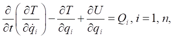
Modeling the contact interaction of the crosshead and guides is reduced to solving a dynamic nonlinear problem of the mechanics of a deformable solid body. In this formulation, it represents a system consisting of a crank shaft, connecting rod, and crosshead-plunger. During the pump operating cycle, non-stationary dynamic stresses arise in the structural elements, and the contact interaction is characterized by a time-varying contact area and force. The motion of the mechanical system is described by the Lagrange equation of the second kind:
 (1)
(1)
where T — kinetic energy of the system; U — potential energy; Qi — generalized force; qi — generalized speed; i — number of degrees of freedom of the given system.
The formulation of the FEM in terms of absolute coordinates takes into account small elastic deformations and the motion of the body as a whole. This formulation covers the entire spectrum of possible problems in the area under consideration, but it is very complex both for its study and for carrying out practical calculations. Therefore, the application of this approach in problems in which elastic bodies participate in macromotion, but are subject to only small deformations, often turns out to be unjustified from the point of view of efficiency.
The most effective method of model reduction is the Craig-Bampton method, widely known as dynamic reduction or the method of coupled substructures. When deriving the equations of the dynamics of elastic bodies subject to global motion and small deformations, the following additional approximation is introduced: the inertia of the elastic structure is concentrated in the nodes of its FEM model. This approximation makes it possible to derive the equations of dynamics quite simply. These equations themselves turn out to be simple. The Craig-Bampton method determines the matrices of the generalized mass and generalized rigidity through the modal transformation [12].
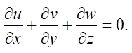
The study of hydrodynamic parameters of the lubricating layer is based on the combination of the Reynolds model and the Stokes model in numerical simulation.
Continuity equation:
 (2)
(2)
Navier-Stokes equations for the model of motion of a viscous incompressible medium [13]:
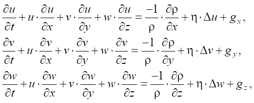 (3)
(3)
where v, w, u — components of the speed vector in the Cartesian coordinate system x, y, z; η — kinematic viscosity; gx, gy, gz — components of mass forces; ρ — density of matter.
The Reynolds-Stokes-Galerkin finite element method (R-SGFEM) with sliding boundary conditions was used to model and study the hydrodynamic lubrication. The effects were obtained on the basis of the Stokes equation, which was calculated by the Galerkin finite element method [14]. Among them, the modified Reynolds equation effectively handles the sliding boundary with different degrees of slippage. The Stokes equation solves the problem of recirculation in micro-channels. The Galerkin method with elements can accurately simulate the pressures and speed in the lubricating field with high accuracy and good adaptation to the shape of the boundaries. The motion of a continuous medium is described by a system of hydrodynamic equations.
Mathematical dependences are supposed to be presented in the form of regression equations obtained from the results of a numerical experiment. To construct regression equations, it is supposed to apply multivariate regression analysis using the theory of experimental design [15].
Research Results. As a calculation model for the numerical experiment, a section of a plunger pump was simulated consisting of: crank shaft (1), connecting rod (2), crosshead (3), crosshead guides (4), rod (5), plunger (6), seal pack (7) (Fig. 1). The materials of the elements used in the dynamic calculation were: steel with an elastic modulus of 207 GPa (crank shaft, connecting rod, crosshead-plunger), bronze with an elastic modulus of 106 GPa (guides) and 100 GPa (plunger seals).
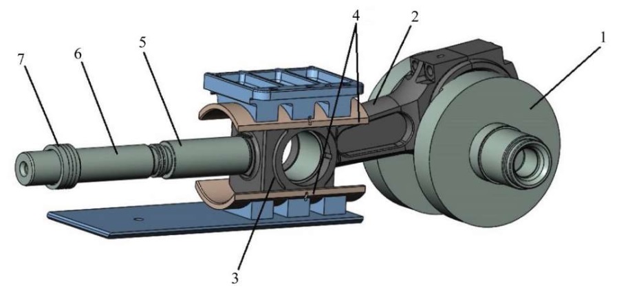
Fig. 1. Plunger pump section
The system was considered from the point of view of the “flexible body” model with six modes. An analysis of the crosshead motion in the field of gravitational forces was performed for each element of the section [16]. The connections (contact, rotation) were redefined, the shaft rotation frequency was set to 80 rpm (480 deg./s). Maximum plunger pressure was 105 MPa, plunger diameter — 80 mm. The pressure from the pumped medium on the plunger during the injection process was modeled by a spring with the appropriate stiffness, taking into account the plunger stroke of 164 mm. At suction, the spring is automatically disconnected. The dynamic model is shown in Figure 2.
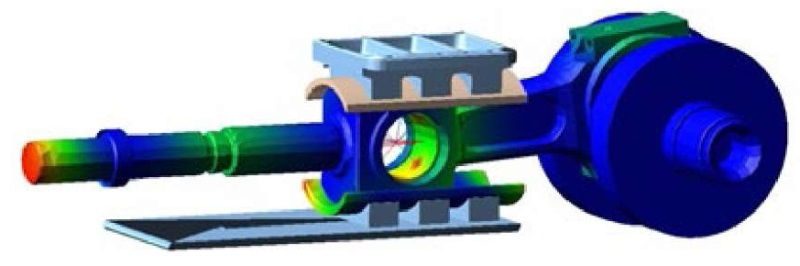
Fig. 2. Dynamic research model
Using this model, the maximum load on the lower crosshead guide was specified to be 43.5 kN, and its position corresponding to this load was determined. All further calculations were performed for this load value. Based on the determined position of the maximum load on the lower crosshead guide, the calculated hydrodynamic model shown in Figure 3 was simulated. The gap between the crosshead and the guide was 0.35 mm. The thickness of one of the six calculated boundary layers of the hydrodynamic calculation was 0.03 mm.
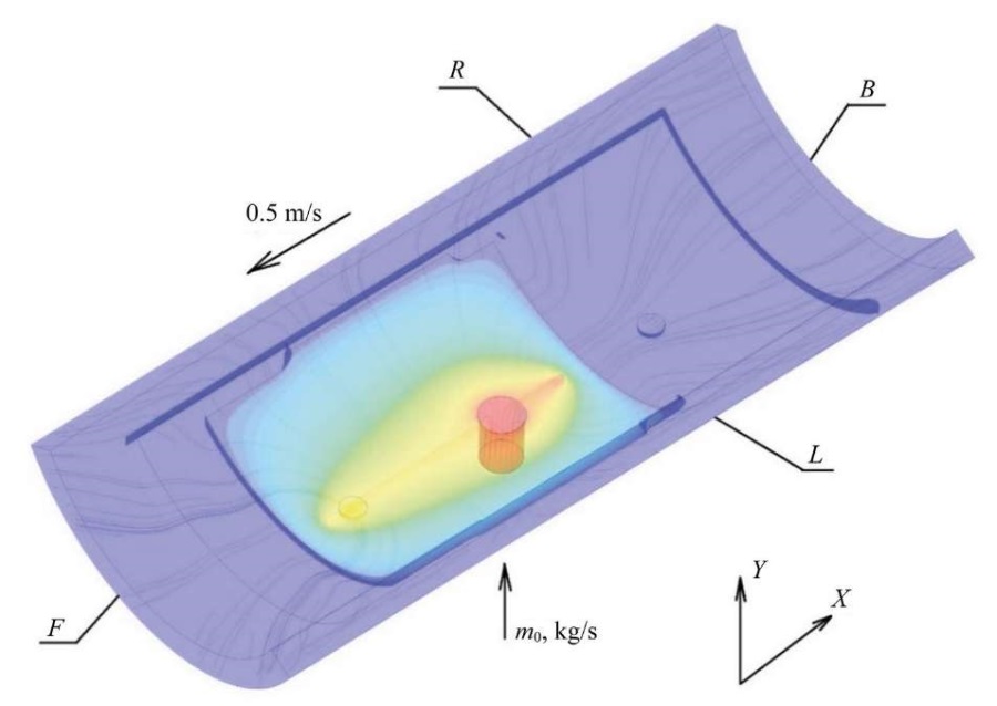
Fig. 3. Computational hydrodynamic model
The study was based on the following hypotheses and assumptions:
The following parameters are accepted as factors affecting the provision of hydrostatic conditions for a flat plain bearing, which includes the crosshead-guide assembly under consideration:
The lubrication pressure was set through the lubrication flow rate at the system input. A preliminary regression analysis was performed to determine the relationship between these parameters. The pressure was measured for a fixed volume of 125 cm³ and a temperature of 50°C. The results are shown in Figure 4.
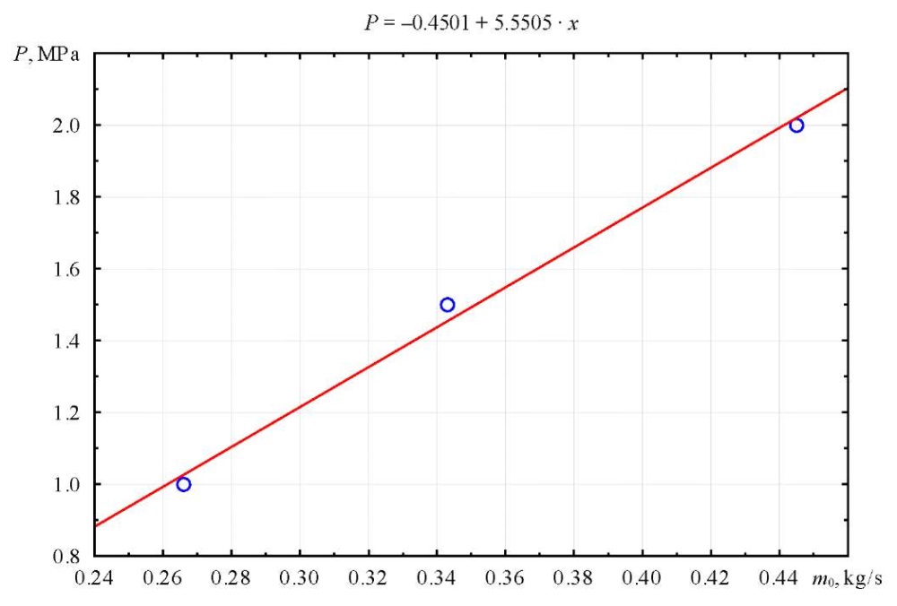
Fig. 4. Relationship between pressure Fсм and lubricant flow rate m0 at the system input
The results presented in Figure 3 show a directly proportional, close to linear dependence and confirm the correctness of using the lubricant flow rate at the input to the system to simulate the process of setting the required pressure.
To conduct a full factorial experiment 23, the variation intervals presented in Table 1 were determined, and the design matrix was compiled (Table 2).
The output parameters were: the force from the lubricating layer acting on crosshead Fкр, N and the lubricant flow rate at the outlet of the system, defined as the amount of liquid flowing through the gaps R, B, L, F.
Table 1
Intervals of Variation of Factors
|
Factor levels |
Variation factors |
||
|
х1 |
х2 |
x3 |
|
|
Design option (volume of lubrication system, cm³) |
Temperature, °С |
Pressure in lubrication system, MPa |
|
|
Lower level (–) |
Option 1 (V1 = 1.532) |
20 |
1.0 |
|
Basic level (0) |
Option 2 (V2 = 4.125) |
50 |
1.5 |
|
Upper level (+) |
Option 3 (V3 = 5.475) |
90 |
2.0 |
The design matrix and the response function values are presented in Table 2.
Table 2
Design Matrix 23 of Full Factorial Experiment
|
Experiment number |
Input parameters |
Output parameters |
|||
|
х1 Design option (volume of lubrication system, m³) |
х2 Temperature, °С |
x3 Pressure in lubrication system, MPa |
y1 Force from lubricant layer on crosshead Fсм, kN |
y2 Lubricant consumption parameter (rate of flow through gap), m kg/s |
|
|
1 |
+ Option 3 |
+ 90 |
+ 2.0 |
15.803 |
0.3127 |
|
2 |
– Option 1 |
+ 90 |
+ 2.0 |
23.278 |
0.2104 |
|
3 |
+ Option 3 |
– 20 |
+ 2.0 |
44.940 |
0.3139 |
|
4 |
– Option 1 |
– 20 |
+ 2.0 |
66.074 |
0.2091 |
|
5 |
+ Option 3 |
+ 90 |
– 1.0 |
93.14 |
–0.1689 |
|
6 |
– Option 1 |
+ 90 |
– 1.0 |
14.005 |
0.1169 |
|
7 |
+ Option 3 |
– 20 |
– 1.0 |
27.310 |
–0.1661 |
|
8 |
– Option 1 |
– 20 |
– 1.0 |
40.969 |
0.1155 |
|
9 |
0 Option 2 |
0 50 |
0 1.5 |
18.579 |
0.2756 |
After processing the results of the numerical experiment, according to the presented planning matrix, dependences were obtained, describing the influence of the factors under consideration on additional parameters:
 (4)
(4)
 (5)
(5)
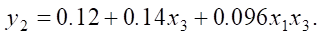
After the transition from the standard scale to the natural scale, the regression equations took the following form:
 (6)
(6)
 (7)
(7)
To visualize the results and perform their further analysis, graphs of the force function acting on the crosshead were constructed. When fixing one of the factors at the basic level, the obtained dependences are presented in Figure 5.
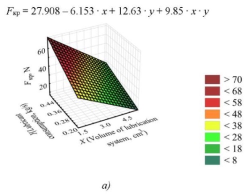
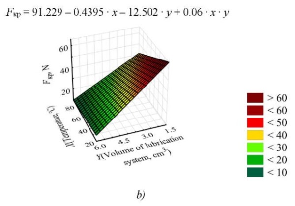
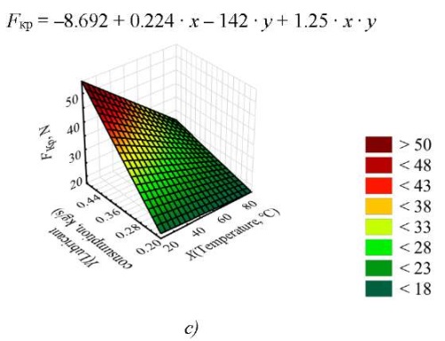
Fig. 5. Dependences of the value of the force acting on the crosshead on the lubricating layer, with different combinations of variation factors: a — value of the force at t = 50°C; b — value of the force at m = 0.346 kg/s; c — value of the force at V = 4.125 cm³
The graph of the dependence describing the lubricant consumption (flow through gaps) is shown in Figure 6.
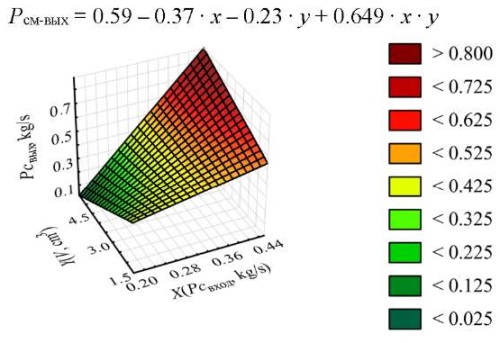
Fig. 6. Lubricant consumption at the system outlet (flow through gaps)
The dependences of the mass flow rate of lubricant at the system outlet (Fig. 6) and the mass flow rate of lubricant supply (Fig. 7) on the volume of gaps filled with lubricant were also determined.
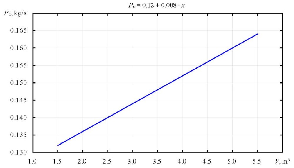
Fig. 7. Dependence of mass flow rate on volume
Discussion and Conclusion. The resulting mathematical model, describing the dependence of the force acting on the crosshead on the lubricating layer, shows that temperature has no great impact on the parameter under consideration, since the coefficient of the regression equation for this factor is recognized as insignificant, and its influence is realized only in pair interaction. This is well illustrated by Figure 4 b, c. The change in the volume of gaps filled with lubricant and the mass flow rate of lubricant at the inlet to the system, simulating the increase in pressure in the lubrication system of the friction unit, have an equal effect. Simultaneous increase of these parameters leads to a decrease in the force acting on the crosshead and maintaining the hydrostatic mode of operation of the unit when the values are equal to the normal force pressing the crosshead against the guides. It is determined that an increase in volume leads to a decrease in pressure in the system, and the desired effect is not achieved (Fig. 4 a). When fixing the pressure in the lubrication system, an increase in the volume of gaps filled with lubricant results in an increase in the force being studied and gives a positive effect (Fig. 4 b). Similarly, fixing the gap with increasing pressure leads to an increase in the force of lubricant pressure on the crosshead (Fig. 4 c). The results of the numerical experiment do not contradict the conclusions made in works that describe basic equations of the hydrodynamic theory of lubrication [9], the rationale for the selection of initial and boundary conditions [10], as well as those papers that consider various methods of supplying lubricant to the friction unit [16]. These results can be used in further research.
The equations obtained for the mass flow rate of lubricant at the system outlet, defined as its outflow through the gaps, show that it depends on the parameters of the mass flow rate at the system inlet (lubricant supply to the unit) and the volume of the gaps. The other factors considered do not affect this parameter. In this case, an increase in volume leads to a decrease in the force acting on the crosshead, and an increase in mass flow leads to an increase in it (Fig. 5). The analysis of the relationship between the mass flow rate of lubricant at the outlet of the system and the volume of the gaps allows us to establish that the ratio of the increase in flow through the gaps to the increase in volume is approximately ½. This shows that to maintain the pressure in the system at the same level with an increase in the volume of the gaps, a twofold increase in the mass flow rate of lubricant when feeding into the system is required.
To determine the extremum for each of the parameters under consideration that affect the process of establishing the hydrostatic mode and identify the optimal value of the initial operating parameters of the unit, it is necessary to conduct a second-order experiment that takes into account the patterns identified in this work.
1. Eckhouse G. United States Hydraulic Fracturing’s Short-Cycle Revolution and the Global Oil Industry’s Uncertain Future. Geoforum. 2021;127:246–256. https://doi.org/10.1016/j.geoforum.2021.07.010
2. Shaowen Mao, Kan Wu, George Moridis. Integrated Simulation of Three-Dimensional Hydraulic Fracture Propagation and Lagrangian Proppant Transport in Multilayered Reservoirs. Computer Methods in Applied Mechanics and Engineering. 2023;410:116037. https://doi.org/10.1016/j.cma.2023.116037
3. Huiying Tang, Philip H Winterfeld, Yu-Shu Wu, Zhao-qin Huang, Yuan Di, Zhengfu Pan, et al. Integrated Simulation of Multi-Stage Hydraulic Fracturing in Unconventional Reservoirs. Journal of Natural Gas Science and Engineering. 2016;36A:875–892. https://doi.org/10.1016/j.jngse.2016.11.018
4. Chen Yang, Xingwen Wu, Maoru Chi, Wubin Cai, Zikui Ma, Xuesong Yao. A Load Estimation Model for Axle Box Bearings of High-Speed Trains Based on Vehicle Dynamic Response. Mechanical Systems and Signal Processing. 2024;221:111728. https://doi.org/10.1016/j.ymssp.2024.111728
5. Vasilenko VV, Kirishchieva VI, Mukutadze MA, Shvedova VE. Investigation of the Wear Resistance of the Journal Bearing with Polymer-Coated Grooved Support Ring. Advanced Engineering Research (Rostov-on-Don). 2022;22(4):365–372. https://doi.org/10.23947/2687-1653-2022-22-4-365-372
6. Polyakov RN, Savin AL. The Method of Long-Life Calculation for a Friction Couple “Rotor – Hybrid Bearing”.In: Proc. 7th International Conference on Coupled Problems in Science and Engineering. Barcelona: CIMNE; 2017: P. 433–440. URL: https://upcommons.upc.edu/bitstream/handle/2117/190572/Coupled-2017-39-The%20method%20of%20longlife.pdf?sequence=1&isAllowed=y (accessed: 20.07.2024).
7. Novotný P, Jonák M, Vacula J. Evolutionary Optimisation of the Thrust Bearing Considering Multiple Operating Conditions in Turbomachinery. International Journal of Mechanical Sciences. 2021;195:106240. https://doi.org/10.1016/j.ijmecsci.2020.106240
8. Shutin DV, Polyakov RN. Active Hybrid Bearings as Mean for Improving Stability and Diagnostics of Heavy Rotors of Power Generating Machinery. IOP Conference Series: Materials Science and Engineering. 2020;862(3):032098. http://doi.org/10.1088/1757-899X/862/3/032098
9. Kolesnikov IV, Mukutadze AM, Avilov VV. Ways of Increasing Wear Resistance and Damping Properties of Radial Bearings with Forced Lubricant Supply. In: Radionov A, Kravchenko O, Guzeev V, Rozhdestvenskiy Y (eds). Proc. 4th International Conference on Industrial Engineering. Cham: Springer; 2019. P. 1049–1062. http://doi.org/10.1007/978-3-319-95630-5_110
10. Polyakov R, Majorov S, Kudryavcev I, Krupenin N. Predictive Analysis of Rotor Machines Fluid-Film Bearings Operability. Vibroengineering Procedia. 2020;30:61–67. http://doi.org/10.21595/vp.2020.21379
11. Hemant Kumar Gurve, Rajesh Kumar Satankar. Modal and Harmonic Analysis of Stiffened Plate Using First-Order Shear Deformation Theory. Materials Today: Proceedings. 2022;51(1):325–331. https://doi.org/10.1016/j.matpr.2021.05.416
12. Yudakov AA. Principles of Flexible Body General Dynamic Equations Derivation Based on the Craig–Bampton Model and Their Practically Significant Ap-proximations.Bulletin of the Udmurt University. Mathematics. Mechanics. Computer Science. 2012;3:126–140. URL: http://vst.ics.org.ru/uploads/vestnik/3_2012/12-03-12.pdf (accessed: 20.07.2024).
13. Radchenko SG, Lapach SN. Basic Concepts of Multiple Regression Analysis. Mathematical Machines and Systems. (In Russ.) 2013;(1):150–156.
14. Xia Tao, Jiaxiong Hao, Yu Zhang. The Uniform Convergence of a Weak Galerkin Finite Element Method in the Balanced Norm for Reaction–Diffusion Equation. Mathematics and Computers in Simulation. 2024;220:445–461. https://doi.org/10.1016/j.matcom.2024.02.001
15. Polyakov RN, Savin LA, Vnukov AV. Mathematical Model of the Non-Contact Finger Seal with Active Management of the Clearance. Fundamental and Applied Problems of Technics and Technology. 2018;327(1):66–71.
16. Kornaeva EP, Kornaev AV, Kazakov YuN, Polyakov RN. Application of Artificial Neural Networks to Diagnostics of Fluid-Film Bearing Lubrication. IOP Conference Series: Materials Science and Engineering. 2020;734:012154. http://doi.org/10.1088/1757-899X/734/1/012154
Marina V. Korchagina, Cand.Sci. (Eng.), Associate Professor of the Machinery and Equipment of the Oil and Gas Complex Department
1, Gagarin sq., Rostov-on-Don, 344003
Valentin N. Stepanov, Senior Lecturer of the Machinery and Equipment of the Oil and Gas Complex Department
1, Gagarin sq., Rostov-on-Don, 344003
Sergey O. Kireev, Dr.Sci. (Eng.), Professor, Head of the Machinery and Equipment of the Oil and Gas Complex Department
1, Gagarin sq., Rostov-on-Don, 344003
Alexey R. Lebedev, Cand.Sci. (Eng.), Associate Professor of the Machinery and Equipment of the Oil and Gas Complex Department
1, Gagarin sq., Rostov-on-Don, 344003
Korchagina M.V., Stepanov V.N., Kireev S.O., Lebedev A.R. Investigation of Parameters Influencing the Establishment of Hydrostatic Mode in the Crosshead-Guide Assembly of High-Pressure Plunger Pump. Advanced Engineering Research (Rostov-on-Don). 2024;24(4):316-327. https://doi.org/10.23947/2687-1653-2024-24-4-316-327. EDN: TSFHRJ

Advanced Engineering Research (Rostov-on-Don)
ISSN 2687-1653 (Online)
Contact with: Publisher / Editorial Office of the Journal
Publisher: Don State Technical University - DSTU, Rostov-on-Don, Russia - https://donstu.ru/en/
Editor-in-Chief: Alexey N. Beskopylny, Dr.Sci. (Eng.), Professor, Vice-Rector, Don State Technical University (Rostov-on-Don, Russia)
Don State Technical University
1, Gagarin Sq., Rostov-on-Don, 344003, Russia
tel.: +7 (863) 2738-372, e-mail: vestnik@donstu.ru
16+
Processing of personal data


