


Contents
Scroll to:
https://doi.org/10.23947/2687-1653-2024-24-4-347-359
EDN: BQOJNU
Scroll to:
Introduction. Energy conservation is an urgent topic of research in the field of mechanical engineering all over the world. A particular direction in these studies is the search for energy-efficient methods of testing technical systems, which allow the most accurate prediction of the reliability of the designed equipment. The duration of resource tests established by technical conditions and GOSTs causes an irreversible loss of energy, amounting to more than 1.5 resource of the tested machine, and the energy lost in the form of “harmful heat” is released into the environment. Therefore, the problem of energy saving during testing is given special attention. One of the ways of energy saving under testing of hydraulic machines is energy recovery. However, in papers devoted to energy recovery during testing of hydraulic machines, the problems of energy recovery during testing of rotary hydraulic machines were solved, and for reciprocating hydraulic machines, the problem of energy recovery during testing of plunger hydraulic cylinders was solved. The results of these studies cannot be directly used for testing reciprocating hydraulic cylinders. In this regard, the objective of this work has been formulated — to develop the structure and basic scheme of a test bench for reciprocating hydraulic cylinders, providing the recovery of part of the energy spent on testing, due to which the energy efficiency of the testing process is significantly increased.
Materials and Methods. The paper used methods for modeling the process of stand functioning based on the application of the theory of volumetric rigidity. To carry out preliminary calculations of the stand operation process, a computer program based on the SimInTech software package was developed.
Results. A structural and schematic diagram of a test bench for reciprocating hydraulic cylinders has been developed. A mathematical expression has been obtained that provides a preliminary assessment of the test efficiency coefficient. A computer program based on the SimInTech software package has been created, which allows the design parameters of the stand affect its operational characteristics, including the coefficient of energy efficiency of the test process.
Discussion and Conclusion. The preliminary calculations of the operating characteristics of the stand showed that the efficiency coefficient of the proposed stand was 1.7. It can be increased by conducting additional studies aimed at obtaining rational design parameters of the stand. The proposed stand provides testing of reciprocating hydraulic cylinders with recovery of part of the expended energy, and its mathematical model allows using the numerical methods in calculations. This significantly simplifies the calculation process and increases the accuracy of the calculations. At the same time, it is possible to obtain rational parameters of the stand already at the design stage, without resorting to expensive and labor-intensive field studies.
Zenin A.R., Rybak A.T., Beskopylny A.N., Pelipenko A.Yu., Serdyukova Yu.A. Testing Bench for Reciprocating Hydraulic Cylinders with Energy Recovery: Structure, Simulation, and Calculation. Advanced Engineering Research (Rostov-on-Don). 2024;24(4):347-359. https://doi.org/10.23947/2687-1653-2024-24-4-347-359. EDN: BQOJNU
Introduction. Most critical criteria of the quality of modern engineering products are their reliability and energy efficiency. Reliability is maintained at various stages of the product life cycle [1]: at the stages of theoretical research [2], development [3], production [4], and operation [5]. Energy efficiency is of great importance in the running of continuously operating drives of technological [6], transport [7], loading-and-unloading machines [8], hydraulic excavators [9], and other machines and mechanisms. Energy saving acquires special interest in the operation of highly loaded machines [10], their testing [11], and diagnostics [12].
At present, when testing hydraulic machines, loading systems are often used in the form of loading devices that consume a significant amount of hydraulic or mechanical energy resources, which are inefficiently used and eventually irretrievably lost.
One of the most important areas of improvement and development of new testing systems for hydraulic machines is moving away from traditional hydraulic motor loading systems (mechanical, hydraulic, electrical and other braking systems), which cause significant unproductive energy losses, to systems with energy recovery.
Therefore, the issue of maintaining energy recovery during testing is a relevant area for increasing energy saving of hydraulic machines. A very promising design in this case is the test bench for rotary hydraulic machines [13], which can be used as a loading system for a recuperative system of the “pump – motor – pump” type when testing reciprocating hydraulic machines.
The diagram of the recuperative system of the “pump – motor – pump” type is shown in Figure 1. In this recuperative system, the test energy transferred from the hydraulic pump to the hydraulic motor is returned from the motor to the pump shaft through mechanical transmission II, which reduces significantly its unproductive losses during the test. In this case, the load for the pump is the motor, and the load for the motor is the pump. The energy lost to overcome the internal resistances of the test system is compensated by the electric motor through mechanical transmission I.
Based on the use of a recuperative system of the “pump – motor – pump” type [14], a test stand for hydraulic machines with reciprocating motion (plunger hydraulic cylinders) [15] has been developed, which allows for significant energy saving during the testing of plunger hydraulic cylinders.
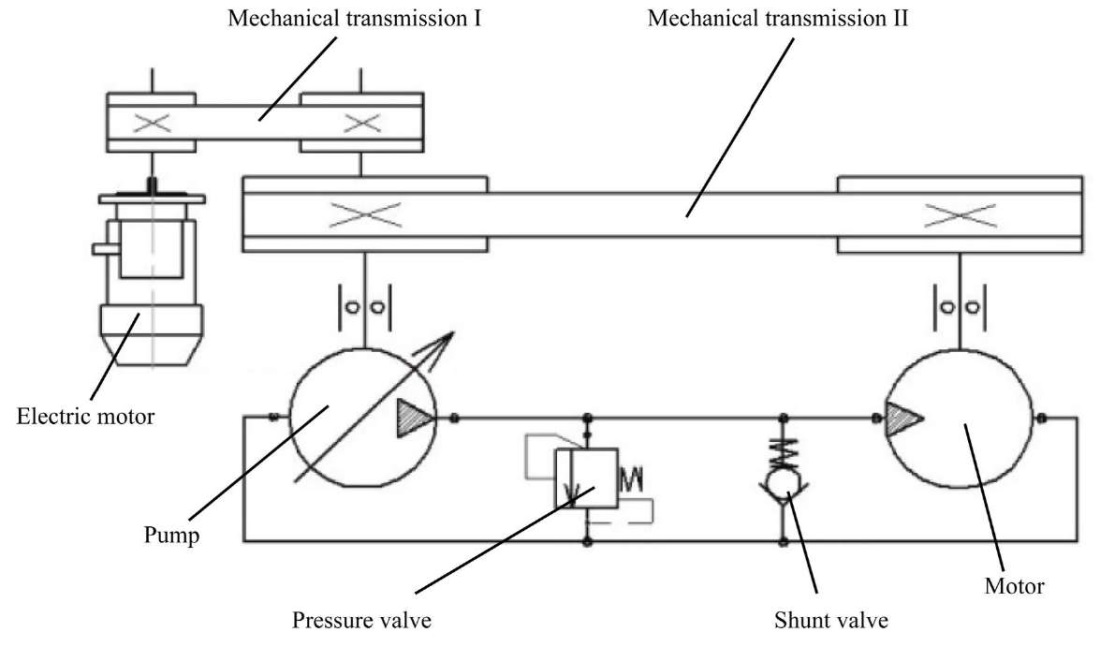
Fig. 1. Scheme of recuperative system of “pump-motor-pump” type
However, the said stand does not allow testing hydraulic piston cylinders. This research objective is to develop the structure and basic diagram of a stand for testing piston hydraulic cylinders, which would provide the recovery of part of the energy spent on testing, as well as its modeling and preliminary calculation of operational characteristics.
Materials and Methods. Based on previously known testing methods, a test stand for checking piston hydraulic cylinders with energy recovery was developed [16]. The structural diagram of the proposed experimental stand is shown in Figure 2.
The stand system includes four hydromechanical subsystems and a system for monitoring and controlling the testing process:
1) primary energy source, which includes an electric motor EM and a hydraulic pump P and is designed to compensate for the energy lost by the system during testing;
2) hydraulic cylinder testing mechanism, including the tested hydraulic cylinders HC1 and HC2, mechanical transmission MT and hydraulic distributor HD;
3) guiding system consisting of check valves CV1, CV2, CV3 and CV4 and designed to control fluid flows when changing the direction of movement of the working parts of hydraulic cylinders;
4) energy recovery system, including hydraulic motor M, pressure hydraulic valve PV and mechanical transmission MT, designed to create a load on the tested hydraulic cylinders and return part of the energy from the shaft of hydraulic motor M to the shaft of hydraulic pump P and implement energy recovery during testing;
5) control and management subsystem “Automatic Control and Management System” (ACMS), designed to monitor the basic technological parameters of the hydraulic cylinder testing process and manage this process. It includes pressure sensors PS1...PS4; speed sensors SS1 and SS2; rotation sensor RS and kilowatt meter KM, designed to measure pressure at characteristic points of the system, the rotation speed of the shafts of the hydraulic pump P and hydraulic motor M, the angle of rotation of the rocker arm RA, the power consumed by the electric motor EM, and further processing of information. For this purpose, the ACMS has an electronic system for processing, displaying on the screen and printing the received information about the progress of the test.
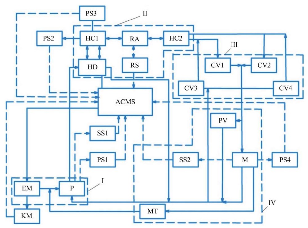
Fig. 2. Structural diagram of the experimental test stand for piston hydraulic cylinders with energy recovery
In the structural diagram (Fig. 2), solid lines show the hydraulic and mechanical connections of the system elements, and dashed lines show the connections of the ACMS elements.
According to the proposed structural diagram, the energy conversion model on the experimental stand will be implemented as follows.
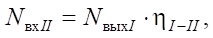
The energy that arises at the output of the primary energy source I as a result of its operation NвыхI, is transmitted with some losses to the input of the hydraulic cylinder testing mechanism II NвхII:
 (1)
(1)
where ηI–II — efficiency factor taking into account the corresponding energy losses.
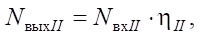
The output power of the hydraulic cylinder test mechanism II after its double conversion within the second subsystem, taking into account the corresponding losses, can be determined from equation:
 (2)
(2)
where NвыхII — output power of the hydraulic cylinder testing mechanism II; ηII — efficiency factor of the hydraulic cylinder testing mechanism II, taking into account energy losses arising in the second subsystem as a result of its double conversion — from hydraulic to mechanical and vice versa. They consist of losses of hydraulic energy in the internal hydraulic lines of the system and losses of mechanical energy during the movement of the pistons of the hydraulic cylinders HC1, HC2, and energy in the mechanical transmission MT from the leading hydraulic cylinder HC1 to the slave hydraulic cylinder HC2.
The power supplied to the input of the third subsystem of the guide system III will be determined taking into account the losses of hydraulic energy between the testing mechanism of hydraulic cylinders II and subsystem III, which is lost to overcome the hydraulic resistance of the corresponding hydraulic lines:
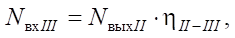 (3)
(3)
where NвхIII — capacity of the hydraulic flow at the input of guide system III; ηII–III — efficiency of the hydraulic transmission (hydraulic system) between the second and third subsystems, taking into account energy losses in the corresponding hydraulic lines.
The capacity of the fluid flow at the outlet of the third subsystem is determined from equation:
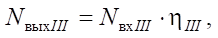 (4)
(4)
where NвыхIII — capacity of the fluid flow at the outlet of subsystem III; ηIII — efficiency of the third subsystem, taking into account energy losses during the operation of the guide system.
The capacity of the fluid flow at the inlet of the energy recovery system is determined from equation:
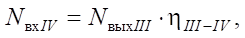 (5)
(5)
where NвхIV — capacity of the fluid flow at the outlet of the fourth subsystem; ηIII–IV — efficiency factor, taking into account the corresponding energy losses.
The output power of the energy recovery system consists of two components: the power of the hydraulic flow transmitted from the drain of the energy recovery system to the input of the hydraulic pump P, and the mechanical energy transmitted from the hydraulic motor shaft to the hydraulic pump shaft through the mechanical transmission MT.
In this case, the total power given by the energy recovery system NвыхIV to the primary energy source can be determined from formula:
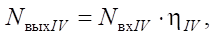 (6)
(6)
where ηIV — total efficiency of the energy recovery system IV.
The total power supplied to the input of the primary energy source NвхI from the energy recovery system, taking into account the total efficiency factor, which considers both mechanical and hydraulic energy losses during its transfer from the output of the energy recovery system to the input of the primary energy source ηIV–I can be determined from formula:
 (7)
(7)
Power NвхI, received at the input of the primary energy source from the output of the energy recovery system is added to power NЭДвых, received from the output of the electric motor EM, and is converted by the pump P into power NвыхI of the working fluid flow at the output of the primary energy source, which can be determined from formula:
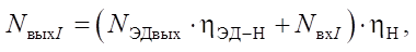 (8)
(8)
where ηЭД–Н — efficiency of the mechanical transmission between the electric motor EM and the pump P; ηН — total efficiency of the pump.
 (9)
(9)
where NЭДвх — power at the input of the electric motor EM (power consumed by the electric motor from the power supply network); ηЭД — efficiency of the electric motor.
The joint solution to equations (1)–(9) allows us to obtain equation:
 (10)
(10)
or
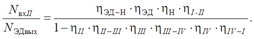 (11)
(11)
In the right part of equation (11), we see the ratio of the power supplied to the tested hydraulic machines (HC1, HC2), to the power consumed by the electric motor of the power source of the test system I. This is nothing more than the efficiency factor of the test system kэфф. Thus, the efficiency factor of the recuperative system under consideration is generally determined from formula:
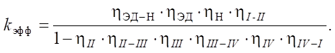 (12)
(12)
From equation (12), it is evident that in the general case, efficiency factor  of the proposed piston hydraulic cylinder testing system is determined by the efficiency factors of the subsystems and elements that make up the testing system. In the numerator of equation (12), there is the product of the efficiency factors of all energy transmission elements — from the primary source of electrical energy to the hydraulic cylinder testing mechanism, and in the denominator, there is the difference between the unit and the product of the efficiency factors of the remaining elements of the system. Thus, to increase the efficiency factor of the testing system, it is required, first of all, to increase the efficiency factors of all the elements that make up the system.
Theoretically, if the efficiency of all elements that make up the hydraulic cylinder testing system are equal to 1, then the efficiency factor of the testing system becomes equal to infinity.
In accordance with the considered structural diagram, presented in Figure 2, a basic diagram of the experimental stand has been developed (Fig. 3). In it, as a hydraulic recuperation system, a hydraulic transmission HST-90 is used, including an adjustable hydraulic pump P1 and a nonadjustable hydraulic motor HM, kinematically connected by mechanical transmission MT2.
The primary energy source I on the experimental stand has a hydraulic connection with the hydraulic cylinder testing mechanism II through hydraulic line l1, which, in turn, is connected through hydraulic lines l13 and l14 to the guide system III, and then through hydraulic line l16 to energy recovery system IV and through hydraulic lines l6, l9 and l10 — to the primary energy source I.
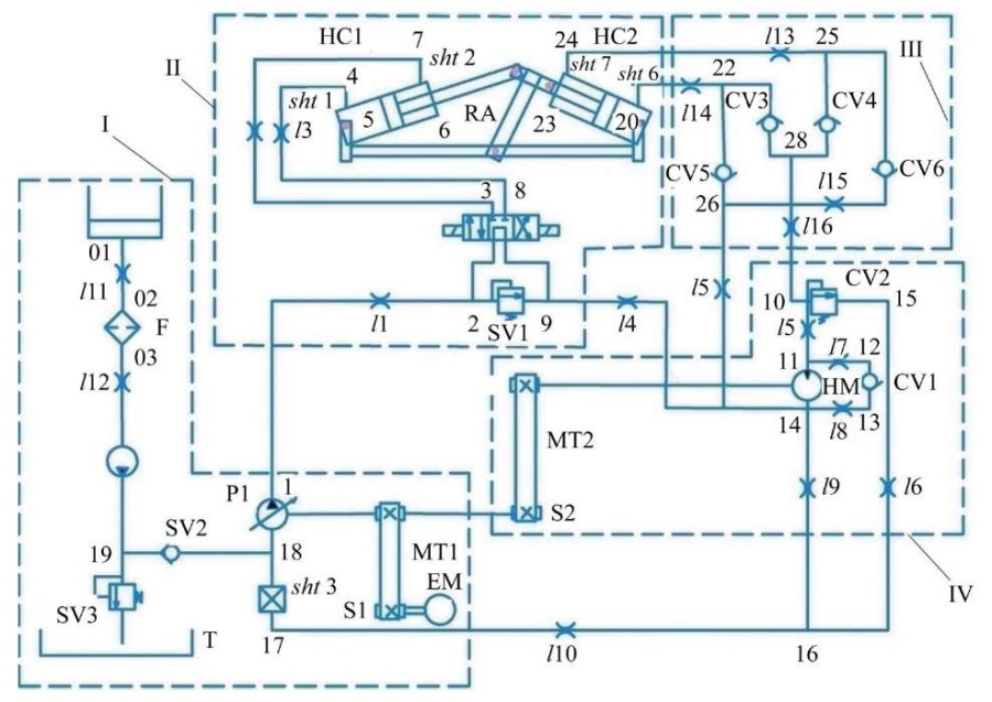
Fig. 3. Hydro-kinematic diagram of the test stand for piston hydraulic cylinders
Thus, the hydraulic system of the stand, like its energy system, is a closed circuit.
The most effective method of preliminary study of the properties of the technical systems being developed is its modeling with subsequent research [17]; therefore, to confirm the correctness of the previously considered method of modeling the test stand for piston hydraulic cylinders, its mathematical model has been developed using the theory of volume rigidity [18]. For this purpose, the hydraulic system of the stand is divided into sections by characteristic points (a total of 32 points, including points 01, 02, 03 and 04 of the feed system).
In accordance with the theory of volume rigidity of hydraulic systems, the time derivative of pressure, taking into account the reduced coefficient of volume rigidity of the section under consideration Cпрi, can be determined depending on the values of incoming Qвхi and outgoing liquid flow rates Qвыхi using formula:
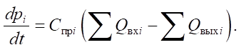 (13)
(13)
The flow rates of the working fluid for substitution into equation (13) are determined in accordance with the actual operating conditions of the system using known dependences [19].
The feed rates of hydraulic pumps P1 and P2 and the flow rate of the hydraulic motor HM are determined taking into account their volume efficiency factors.
Since the shafts of the hydraulic pump S2 and the hydraulic motor S3 are connected through a mechanical transmission, the following dependence is satisfied:
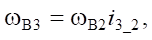 (14)
(14)
where i3_2 — gear ratio of mechanical transmission MT2 of rotation from the shaft of hydraulic motor S3 to the shaft of hydraulic pump S2.
The rotation speed of the hydraulic pump shaft is set by the angular speed of the electric motor shaft S1  and is determined from the ratio:
 (15)
(15)
where i1_2 — gear ratio of mechanical transmission MT1 of rotation from the shaft of hydraulic motor S1 to the shaft of hydraulic pump S2.
The flow rates through the valves (pressure valves PV1…PV3 and check valves CV1…CV6) are determined by their flow characteristics from the ratio:
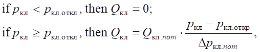 (16)
(16)
where pкл — pressure at the valve inlet; pкл.откр — valve start-to-open pressure; Δpкл.nom — difference between the full valve open pressure at the nominal flow rate and the start-to-open valve pressure; Qкл — actual flow rate of the working fluid through the valve; Qкл.nom — nominal flow rate of the valve.
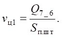
Figure 4 shows the kinematic diagram of the hydraulic cylinder testing mechanism. When modeling its operation, it should be borne in mind that the speed of piston movement of the hydraulic cylinder HC1 is determined by the flow rate of the working fluid supplied to its piston cavity:
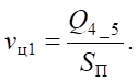 (17)
(17)
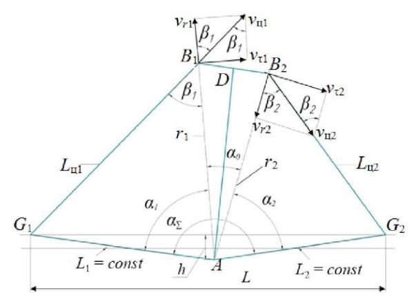
Fig. 4. Kinematic diagram of the hydraulic cylinder testing mechanism
The movement of hydraulic cylinder Lц1 is transmitted to the mechanical transmission MT, which performs a rotational movement around point A.
The angular rotational speed of mechanical transmission MT is determined by the tangential component vτ1 of the movement speed of the piston of hydraulic cylinder HC1. It depends on angle β1 between the direction of its movement and radius r1, that connects the point of rotation of the mechanical transmission MT and point B1 that joins the rod of the hydraulic cylinder HC1 with it:
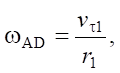
or
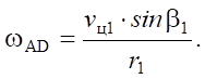 (18)
(18)
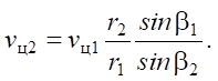
Rotating around point A, mechanical transmission MT transmits movement to the piston of the slave hydraulic cylinder HC2, whose speed vц2 also depends on angle β2 between the direction of its movement and radius r2, that connects the point of rotation of the mechanical transmission MT and point B2 that joins the rod of the hydraulic cylinder HC2 with it:
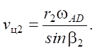 (19)
(19)
Having solved equations (18) and (19) simultaneously, we obtain a formula that determines the relationship between the speed of movement of the pistons of the leading hydraulic cylinder HC1 and the slave hydraulic cylinder HC2:
 (20)
(20)
From the analysis of triangles (according to the law of cosines) AG1B1 and AG2B2, angles β1 and β2 are determined:
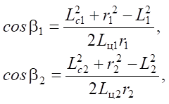
where Lц1 and Lц2 — distances between the axes of the connection of the housings of the corresponding hydraulic cylinders to the stand frame and their rods with the mechanical transmission MT; L1 and L2 — distances from the axis of rotation of the mechanical transmission MT and points G1 and G2 of connection with the stand frame of the housings of hydraulic cylinders HC1 and HC2, respectively.
During the return piston stroke of the slave hydraulic cylinder HC1, the working fluid is supplied to its rod cavity, and then the rest of the calculation formulas remain unchanged.
 (21)
(21)
In dynamic calculations, the movement of the piston of the leading cylinder HC1 is described by the equation of motion:
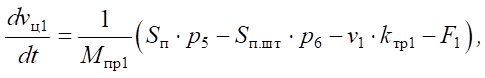 (22)
(22)
 (23)
(23)
where vц1 and xц1 — speed and displacement of the piston of the hydraulic cylinder HC1; Mпр1 — reduced mass; Sп and Sп.шт — working areas of the pistons of the hydraulic cylinders; p5 and p6 — pressure in the corresponding cavities of the hydraulic cylinder HC1; kтр1 — friction factor during movement of the working element of the first hydraulic cylinder HC1, taking into account friction in the transmission mechanism RA; F1 — force of impact on the working body of the leading hydraulic cylinder from the side of the hydraulic cylinder HC2.
Force F1 is determined by formula:
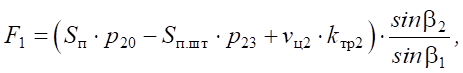 (24)
(24)
where p20 and p23 — pressure in the piston and rod cavities of the slave hydraulic cylinder HC2, respectively; vц2 and kтр2 — speed of movement of the working body of the slave hydraulic cylinder HC2 and friction factor during its movement.
Research Results. Figures 5–9 show the results of the preliminary calculation of the proposed mathematical model of the test stand. The calculations were performed using a special program developed in the SimInTech environment [20]. The calculations allowed us to determine the functional parameters of the stand already at the design stage and take meaningful measures to improve them.
Having analyzed the graphs of the piston motion parameters of the tested hydraulic cylinders (Fig. 5), it can be concluded that the test cycle of the piston hydraulic cylinders HC63.500.16.000 on the proposed stand will last about four seconds. The piston motion speed, when the rod is extended, will be 0.24 m/s, and when it is retracted — 0.32 m/s.
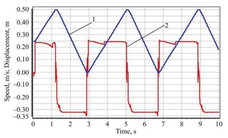
Fig. 5. Change in the parameters of the piston movement of the leading hydraulic cylinder under testing: 1 — displacement; 2 — speed
The graphs (Fig. 5) show that the hydraulic cylinders are exposed to working fluid pressures of 120 to 130 atmospheres under testing. Of particular interest is the fact that during testing, at the moment of reversing the direction of movement of the piston, the pressure at all considered points becomes the same — about 70 atmospheres.
Figure 6 shows data on the pressure at the nodal points of the hydraulic system of the stand under testing.
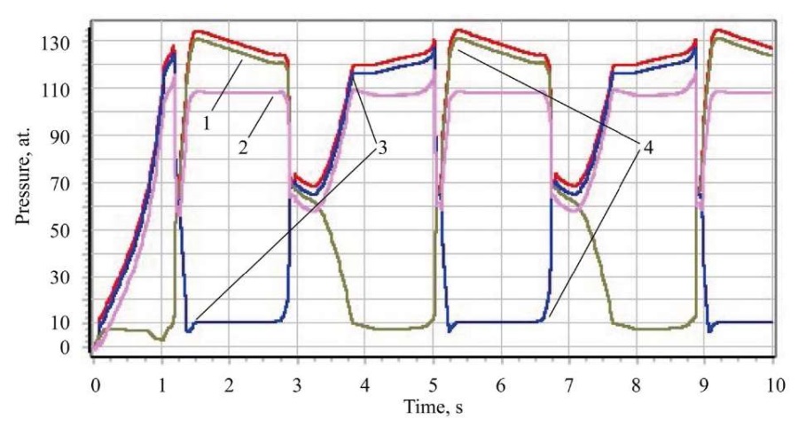
Fig. 6. Pressure change at characteristic points of the hydraulic system of the stand under testing of hydraulic cylinders: 1 — hydraulic pump outlet; 2 — hydraulic motor inlet; 3 — piston cavity of HC1; 4 — rod cavity of HC1
The graphs of pressure variations in low-pressure hydraulic lines, which are shown in Figure 7, allow us to estimate the magnitude and nature of the pressure change at the input to the feed hydraulic pump of the stand. It can be seen that at the moment of reversal of the piston movement of the tested hydraulic cylinders, the pressure in the suction branch of the main hydraulic pump of the stand increases sharply to 70 atmospheres. Particularly noteworthy is the fact that when the direction of the piston movement of the leading hydraulic cylinder changes from extension to retraction, the pressure at the outlet of the feed pump grows less than the setting pressure of its pressure valve. To explain this effect, it should be recalled that the hydraulic system of the stand is essentially a closed system, i.e., the working fluid from the drain of the recovery system enters the suction branch of the main pump of the stand. At some point during the operation of the stand, this fluid is not enough, the main pump receives additional fluid flow from the feed pump. This fact is very important to remember when designing a test stand.
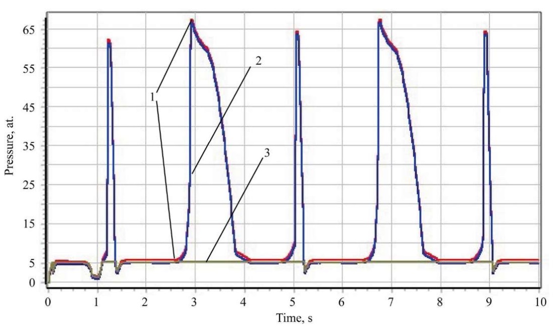
Fig. 7. Change in pressure at characteristic points of the low-pressure hydraulic system under testing of hydraulic cylinders: 1 — output of the hydraulic system of the hydraulic cylinder testing mechanism; 2 — input of the main hydraulic pump; 3 — output of the feed hydraulic pump
The graphs of power variations on the hydraulic machines of the test stand during testing (Fig. 8) show that the highest power during testing of hydraulic cylinders occurs at the output of the hydraulic pump, and the lowest — at the input of the main energy source of the bench — the electric motor. This is the main objective that the authors were trying to achieve by creating a stand with a recuperative system: the recuperative system returns part of the energy spent on testing hydraulic cylinders back to the hydraulic pump, which reduces the overall energy consumption of the primary source, and this provides an increase in the energy efficiency of the testing process. It should also be noted that when the direction of movement of the pistons of the tested hydraulic cylinders is reversed, the power on some elements of the stand takes on a negative value. Obviously, this is the effect of the release of energy accumulated in the system during its elastic deformation, volume compression in the hydraulic system.
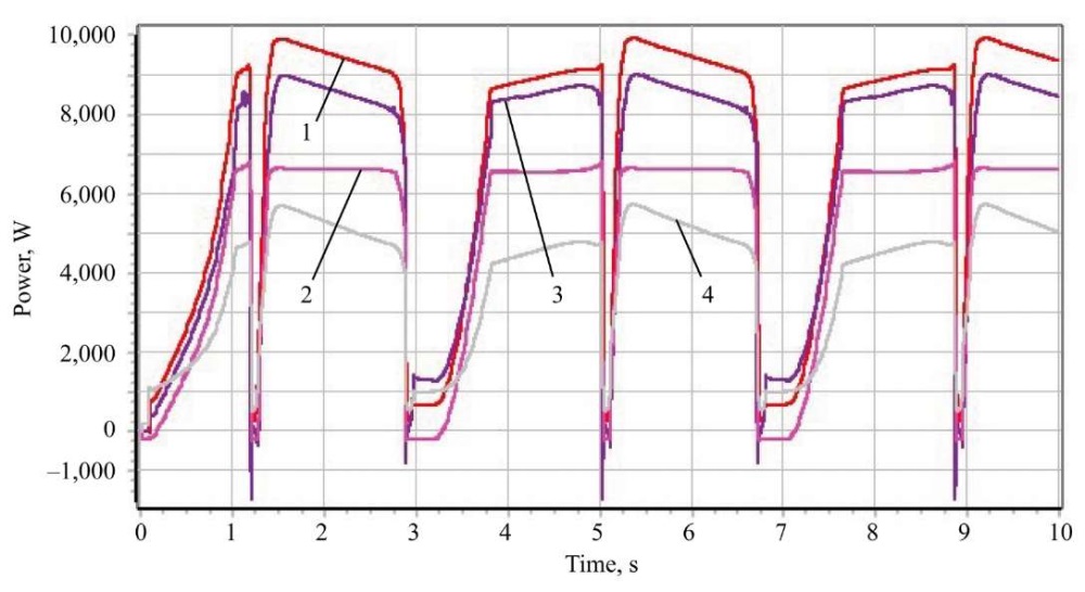
Fig. 8. Change in power on the hydraulic machines of the stand under testing of hydraulic cylinders: 1 — hydraulic pump output; 2 — hydraulic motor shaft; 3 — in the hydraulic cylinder testing system; 4 — electric motor input
The graphs (Fig. 9) show that the instantaneous efficiency coefficient takes on a zero value when the direction of movement of the pistons of the tested hydraulic cylinders is reversed. This is explained by the fact that at this moment, the piston of the hydraulic cylinder stops, and therefore, the power on the tested hydraulic cylinders also goes to zero.
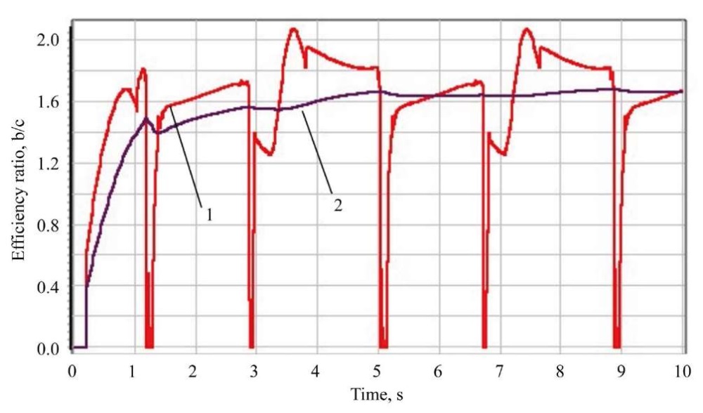
Fig. 9. Test efficiency factors:1 — instantaneous value; 2 — average value
It is also seen that the value of the average test efficiency ratio approaches the value of 1.7. This indicates that the power of the hydraulic cylinder test is 70% greater than the power expended during this test.
Discussion and Conclusion. The results of the research done by the authors and presented in this article show that the proposed stand scheme allows testing piston hydraulic cylinders with a test efficiency factor of 1.7. Considering that tests performed using classical loading methods have an efficiency factor of no more than 0.8–0.9, it can be concluded that the proposed energy recovery scheme is two times more efficient than classical loading methods. That is, when testing the same hydraulic cylinders, the energy consumed is more than two times less than when testing through special loading means (mechanical, hydraulic, etc.) without energy recovery.
The maximum (highest) value of the efficiency coefficient for testing piston hydraulic cylinders using the proposed stand can be determined by equation (12). The proposed mathematical model of the stand and the program developed for its study allow for a preliminary study of the influence of various design and functional parameters of the stand on the test efficiency factor, as a result of which rational values of the design parameters of the stand can be obtained.
1. Suslov AG, Fedorov VP, Gorlenko OA, Il’itsky VB, Totai AV, Khandozhko AV, et al. Fundamental Principles of Technological Support and Increasing the Reliability of Mechanical Engineering Products. Moscow: Innovatsionnoe mashinostroenie; 2022. 552 p. (In Russ.)
2. Teplyakova SV. Justification of the Concept of Creating Practically Trouble-Free Machines. Bulletin of Higher Educational Institutions. North Caucasus Region. Technical Sciences. 2021;210(2):41–45. https://doi.org/10.17213/1560-3644-2021-2-41-45
3. Kuznetsova VN, Savinkin VV. Development of Hybrid Drive’s Construction of a Traversing Platform of an Earthmoving Machine for Implementing Construction Works. The Russian Automobile and Highway Industry Journal. 2015;41(1):17–23. URL: https://vestnik.sibadi.org/jour/article/view/95 (accessed: 20.08 2024).
4. Deryushev VV, Teplyakova SV, Zaitseva MM. Production Facilities Safety Assessment according to the Maximum Values of Machines Reliability. Safety of Technogenic and Natural Systems. 2023;7(2):58–69. https://doi.org/10.23947/2541-9129-2023-7-2-58-69
5. Antipas IR. Modeling the Dynamic Loads Affecting a Bridge Crane during Start-Up. Advanced Engineering Research (Rostov-on-Don). 2024;24(2):190–197. https://doi.org/10.23947/2687-1653-2024-24-2-190-197
6. Nikonov VO, Posmetev VI, Kozlov EV, Borodkin VO. Analysis of Constructive Peculiarities of Hydroficated Technological Machines with Recovery of the Potential Energy of the Working Body with Cargo. Voronezh ScientificTechnical Bulletin. 2019;27(1):4–19.
7. Chmil VP. Reconcilitive Transmission as Means of Improving the Operational Properties of Cars. Mechanization of Construction. 2017;78(8):55–59.
8. Chmil VP. Energy Recovery in Hydraulic Mechanism of Turning Excavator Platform. Mechanization of Construction. 2017;78(2):5–8.
9. Lianpeng Xia, Long Quan, Lei Ge, Yunxiao Hao. Energy Efficiency Analysis of Integrated Drive and Energy Recuperation System for Hydraulic Excavator Boom. Energy Conversion and Management. 2018;156:680–687. http://doi.org/10.1016/j.enconman.2017.11.074
10. Popikov PI, Derepasko IV, Khomenko KG, Rudoy DV, Olshevskaya AV, Rybak AT, et al. Analysis of Studies of Work Processes of Energy-Saving Hydraulic Drives and Devices of Highly Loaded Technological Machines and Equipment. E3S Web of Conferences. 2023;462:01039. https://doi.org/10.1051/e3sconf/202346201039
11. Ustyantsev MV. Improving the Efficiency of the Drive of the Test Stand for Rotary Hydraulic Machines. Cand.Sci. (Eng.), diss., author’s abstract. Rostov-on-Don; 2012. 18 p. (In Russ.)
12. Fominykh AM. Application of Energy-Efficient Diagnostic Method for Hydraulic Drives. Eurasian Union of Scientists. 2014;3(6):46–48. (In Russ.)
13. Rybak AT, Tsybriy IK, Pelipenko AYu. Test Bench for Hydraulic Motors and Pumps with Energy Recovery. RF Patent, no. 204153. 2021. 7 p. (In Russ.)
14. Rybak A, Meskhi B, Rudoy D, Olshevskaya A, Serdyukova Yu, Teplyakova S, et al. Improving the Efficiency of the Drive of the Test Bench of Rotary Hydraulic Machines. Actuators. 2024;13(2):63. https://doi.org/10.3390/act13020063
15. Pelipenko A, Rybak A, Vyborova N, Zubtsov V, Lugantsev D. Energy Saving in Hydraulic Testing Systems. In book: Guda A. (ed) Networked Control Systems for Connected and Automated Vehicles. Cham: Springer; 2022. P. 1889–1896. http://doi.org/10.1007/978-3-031-11051-1_194
16. Rybak AT, Zenin AR, Pelipenko AYu. Test Stand for Piston Hydraulic Cylinders with Energy Recovery. RF Patent, no. 2796721. 2022. 9 p. (In Russ.)
17. Yudin RV, Popikov PI, Uskov VI, Platonov AA, Popikov VP, Kanishchev DA. Mathematical Model of Working Processes of a Chokerless Hauling Grip with an Energy-Saving Hydraulic Drive. Resources and Technology. 2022;19(1):72–86. http://doi.org/10.15393/j2.art.2022.6023
18. Rybak AT, Boguslavskiy IV. Improvement of the Scientific-Methodological Design Principles of the Production Machines Drive Systems. Vestnik of Don State Technical University. 2010;10(2):249–257. https://www.vestnikdonstu.ru/jour/article/view/971/966
19. Boguslavskiy IV, Rybak AT, Chernavskiy VA. Scientific-Methodological Foundations for Designing Drives for Technological Machines. Monograph. Rostov-on-Don: Institute of Management and Innovation of the Aviation Industry; 2010. 276 p. (In Russ.)
20. Abalov AA, Nosachev SV, Zharov VP, Minko VA. Using the SimInTech Dynamic Modeling Environment to Build and Check the Operation of Automation Systems. MATEC Web of Conferences. 2018;226:04003. https://doi.org/10.1051/matecconf/201822604003
Alexander R. Zenin, Head of the Department of Capital Construction and Capital Repairs, Acting Vice-Rector for Capital Construction and Development of the Property Complex, Teacher of the Department of Life Safety and Environmental Protection
1, Gagarin sq., Rostov-on-Don, 344003
Alexander T. Rybak, Dr.Sci. (Eng.), Professor of the Department of Technologies and Equipment for Processing Agricultural Products
1, Gagarin sq., Rostov-on-Don, 344003
Alexey N. Beskopylny, Dr.Sci. (Eng.), Professor, Vice-Rector for Academic and International Affairs, Professor of the Organization of Transportation and Road Traffic Department
1, Gagarin sq., Rostov-on-Don, 344003
Alexey Yu. Pelipenko, Cand.Sci. (Eng.), Associate Professor of the Hydraulics, Hydropneumoautomatics and Heat Management Department
1, Gagarin sq., Rostov-on-Don, 344003
Yuliya A. Serdyukova, Postgraduate student of Life Safety and Environment Protection Department
1, Gagarin sq., Rostov-on-Don, 344003
Zenin A.R., Rybak A.T., Beskopylny A.N., Pelipenko A.Yu., Serdyukova Yu.A. Testing Bench for Reciprocating Hydraulic Cylinders with Energy Recovery: Structure, Simulation, and Calculation. Advanced Engineering Research (Rostov-on-Don). 2024;24(4):347-359. https://doi.org/10.23947/2687-1653-2024-24-4-347-359. EDN: BQOJNU


Advanced Engineering Research (Rostov-on-Don)
ISSN 2687-1653 (Online)
Contact with: Publisher / Editorial Office of the Journal
Publisher: Don State Technical University - DSTU, Rostov-on-Don, Russia - https://donstu.ru/en/
Editor-in-Chief: Alexey N. Beskopylny, Dr.Sci. (Eng.), Professor, Vice-Rector, Don State Technical University (Rostov-on-Don, Russia)
Don State Technical University
1, Gagarin Sq., Rostov-on-Don, 344003, Russia
tel.: +7 (863) 2738-372, e-mail: vestnik@donstu.ru
16+
Processing of personal data


