Contents
Scroll to:
https://doi.org/10.23947/2687-1653-2024-24-4-402-412
EDN: TKWDZL
Scroll to:
Introduction. One of the main requirements to the methods of weld overlay of sealing surfaces of power valve trim parts is to obtain a high-quality wear-resistant pad with minimal penetration and optimal process performance. Currently, arc, electroslag, plasma, beam, induction and other surfacing techniques have been developed and introduced into production. However, the influence of various arc welding processes with a consumable electrode in shielding gas on the geometric parameters of weld beads and metal hardness of sealing surfaces is understudied. The presented research is intended to fill this gap. The objective of its authors is to select such a process of arc welding of beads on parts of the power valve trim with a consumable electrode in shielding gases, which would provide the best workability of the deposited metal.
Materials and Methods. Arc surfacing with a consumable electrode in a mixture of gases was performed on steel plates. The welding torch was moved in a straight line, without transverse oscillations, using the FRC-9 mechanism (Fronius). A microprocessor-controlled inverter-type digital current source TransPulsSynergic 3200 CMT (Fronius) was used as the power supply. The following welding processes were analyzed: MIG/MAG process with self-regulation (Standard mode), synergic process of MIG/MAG method (Synergic mode), short arc process with mechanical separation of electrode metal droplets (CMT-ColdMetalTransfer), and synergic pulse-arc process (PulseSynergic). The short-cut process of bead surfacing was evaluated by the stability of the values of the energy parameters of the bead surfacing mode in time at the same electrode wire feed rates, which were recorded by oscilloscopes, as well as by comparing the geometric characteristics of the deposited beads and the hardness of the deposited metal.
Results. The analysis of experimental data of the geometrics of the weld beads and their complex dimensional characteristics made it possible to establish that the welding engineering requirements for the welded beads are most fully met by long-arc surfacing by the PulseSynergic pulse-arc process.
Discussion and Conclusion. The study and the resulting data make a certain contribution to solving the problem of the influence of arc welding processes on the parameters of weld beads and on the hardness of the metal of sealing surfaces. A detailed analysis of the modes of arc surfacing of beads with a consumable electrode in shielding gases on the trim parts of power valves can be used in further research on this topic. The conclusions of the authors will not only provide considerable theoretical assistance to scientists, but will also make adjustments to the activities of practitioners.
Rogozin D.V., Lenivkin V.A. Selection of the Process of Arc Welding of Sealing Surfaces of Power Valves with a Consumable Electrode in the Shielding Gas. Advanced Engineering Research (Rostov-on-Don). 2024;24(4):402-412. https://doi.org/10.23947/2687-1653-2024-24-4-402-412. EDN: TKWDZL
Introduction. One of the main results of the mechanized weld overlay of sealing surfaces of power valve trim parts in protective gases is the production of a high-quality wear-resistant weld layer of metal with minimal penetration [1]. The requirements for the metal of the weld layer are divided into three groups: welding and process, operational, and economic [2].
Welding and process requirements determine the absence of pores, cracks, areas with embrittled structure, and other welding defects that arise under surfacing. The deposited metal should be easily formed, have good slag separation in a wide range of modes both in single-layer and multi-layer surfacing. Thermal expansion coefficients of the base and weld metal should be comparable. Otherwise, cold cracking may occur in the fusion zone with subsequent peeling of the weld metal. The content of various elements in the weld metal determines its structure, phase composition, hardness, and wear resistance [3].
The group of welding and process requirements also includes the productivity of arc surfacing in protective gases, which fluctuates up to 8 kg/h, and the layer thickness — up to 10 or more millimeters. Higher productivity can be achieved by using more powerful heat sources. However, when heating above a certain value, the proportion of the base metal in the deposited metal increases, harmful elements pass from it, the volume of liquid metal grows, and the primary structure of the deposited metal becomes larger [4]. In some cases, slow cooling of the deposited layer and its tempering reduce wear resistance and other quality indicators of the metal of the deposited layer. Contradictions often arise between the possibility of raising the productivity of deposition through increasing the power of the heat source and the quality of the deposited layer [5]. Therefore, technology factors determined by the method and mode of deposition affect the size and distribution of structural components in the deposited metal, its strength and quality.
The welding and process properties of the deposited bead are determined by the type of deposition process. One of the fundamental properties of the deposited metal of the sealing surfaces of power valves is its hardness [6]. Currently, arc, electroslag, plasma, beam, induction and other techniques of surfacing are widely used to form sealing surfaces on parts of energy valve trims [7][8]. An effective and well-researched method of surfacing is arc surfacing with a consumable electrode in protective gases [9][10].
The result of intensive development of power semiconductor devices (power transistors) in the last decades of the 20th century was the creation of new modern welding low-inertia, high-speed power sources (welding rectifiers), equipped with inverter converters capable of controlling process modes at the microcycle level. This expands significantly the scope of application of arc welding and surfacing due to the possibility of implementing specific welding processes with a short and long arc at the hardware level [11]. However, the influence of various arc welding processes with a consumable electrode in a protective gas on the geometric parameters of the deposited beads and the hardness of the deposited metal has not been sufficiently studied. In this regard, the objective of this research is to determine the process of arc surfacing of beads with a consumable electrode in protective gases on the parts of the trim of power valves, which would provide the best welding and process properties of the deposited metal.
Materials and Methods. The effect of various arc welding processes produced by a consumable electrode in protective gases on the geometric dimensions of the beads and on the hardness of the metal of the deposited surfaces was investigated under mechanized surfacing with a reverse polarity current of individual straight beads on plates (made of steel 20 GOST 1050 with a thickness of 10 mm, a length of 300 mm and a width of 150 mm) with electrode wire Sv-08G2S with a diameter of 1.2 mm in a mixture of protective gases (82% Ar + 18% CO2). Protective gas consumption was 13–15 l/min, without transverse oscillations of the welding torch. The distance between the end of the contact tip and the surface of the welded plate was maintained constant — 20 mm.
The weld beads were arranged parallel at a distance of at least 20 mm from each other. Each subsequent bead was welded after the preceding one had been thoroughly cleaned of slag. The temperature of the metal of the preceding bead was no more than 100°C.
The surfacing speed was 30 cm/min (18 m/h) and was provided by the FRC-9 surfacing torch movement mechanism (Fronius).
The registration of electrical parameters during the entire process of bead surfacing (current value and voltage drop across the interelectrode gap) was performed by the IRSP-11 welding process measuring and recording device. Reading and viewing the registration results in the form of oscillograms was performed on a personal computer using the IRSP_Read software.
The hardness of the deposited metal was measured according to GOST 6996 on samples in the cross section after the application of attack-polishing method in a 4% alcohol solution of nitric acid according to Rockwell (HRC) on a Metrotest ITBRV-187.5-M hardness gauge. The hardness value was determined as the arithmetic mean at three points.
For surfacing the beads, a digital inverter-type current source with microprocessor control TransPulsSynergic 3200 CMT (Fronius) was used, which had a sufficient number of synergic programs for controlling the electrical parameters of the welding mode and provided 4 types of surfacing process:
The rational process of bead surfacing was assessed by the stability of the values of the energy parameters of the bead surfacing mode over time at the same feed rates of the electrode wire, which were recorded by oscillograms (Fig. 1–4). The results are given in Tables 1–3.
Research Results. The energy parameters of the surfacing mode are:
For short arc surfacing:
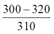
The MIG/MAG (Standard mode) arc surfacing process was carried out with a constant feed rate of the electrode wire νпп (hereinafter referred to as the electrode) with self-regulation of its melting, without the use of regulating devices, with a long arc (without short circuits) in an inert, active protective gas and their mixture, with a short arc (with short circuits of the inter-arc gap). The parameters of the MIG/MAG process surfacing mode are given in Table 1 (modes 1–3). A section of the MIG/MAG process oscillogram (Standard mode) is shown in Figure 1.
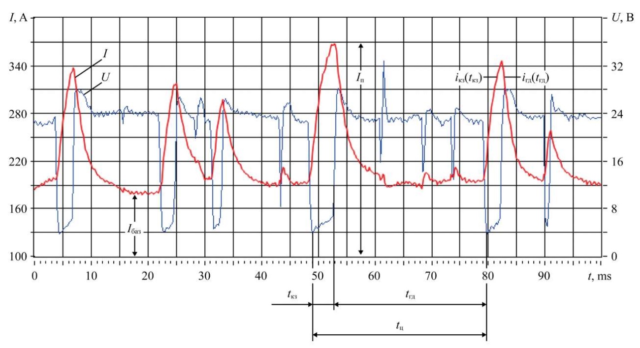
Fig. 1. Oscillogram of MIG/MAG process (Standard mode): surfacing mode 2 in Table 1
Table 1
Parameters of the Surfacing Modes by MIG/MAG Process and MIG/MAG (Synergic mode)
|
Mode No. |
νпп m/min |
Process current value, A |
Voltage, V |
Duration, ms |
Short circuit frequency, 1/s |
||||
|
Iср |
Iбаз |
Iп |
Uпр |
tкз |
tгд |
tц |
fкз |
||
|
1 |
5.0 |
|
|
|
19 |
|
|
|
59 |
|
2 |
6.5 |
|
|
|
21 |
|
|
|
51 |
|
3 |
8.0 |
|
|
|
25 |
|
|
|
21 |
|
4 |
5.0 |
|
|
|
19 |
|
|
|
52 |
|
5 |
6.5 |
|
|
|
19 |
|
|
|
35 |
|
6 |
8.0 |
|
|
|
24 |
|
|
|
33 |
Note. Numerator shows the smallest and largest values of the electrical and time parameters of the surfacing processes. Denominator shows the average value of the corresponding parameters during the bead surfacing time.
The synergistic process of the MIG/MAG method (Synergic mode) is a self-organizing system that automatically changes its process control structure by selecting the required synergistic program. In Synergic mode, setting one parameter of the surfacing mode leads to an automatic change in all other process parameters by switching to a new program that maintains a stable surfacing process (Table 1, modes 4–6). A section of the oscillogram of the synergic process of the MIG/MAG method (Synergic mode) is shown in Figure 2.
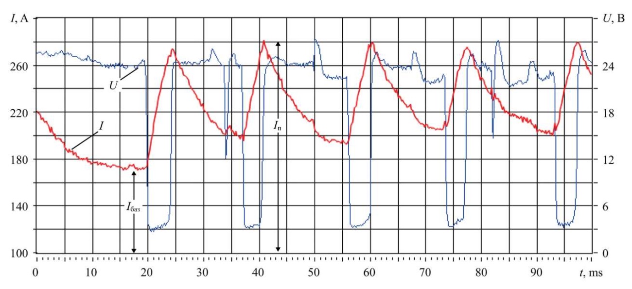
Fig. 2. Oscillogram of the synergistic process of the MIG/MAG method (Synergic mode): parameters of surfacing mode 5 in Table 2
Under short arc surfacing using the MIG/MAG method (Standard mode) and under the synergic process using the MIG/MAG method (Synergic mode), the current during a short circuit increases (short-circuit current curve iкз(tкз)) according to the exponential law. When the bridge is interrupted, the arc burning current (arc burning current curve iгд(tгд)) also decreases according to the exponential law, as in the case of surfacing from parametric welding rectifiers that do not have an inverter converter [12][13].
A reliable interruption of the bridge in the specified surfacing processes occurs with a certain current reserve Iп ≤ 0.7I0, where Iп — peak current value at the moment of interruption of the liquid bridge between the electrode tip and the weld pool; I0 = Uxx / Zц — steady-state short-circuit current; Uxx — voltage at the output of the power source; Zц — complex electrical resistance of the surfacing circuit [12].
It is known that the nature of the process with frequent short circuits of the arc gap depends on the rate of increase of the current at the beginning of short circuit iкз(tкз) and at the interruption of the liquid bridge iгд(tгд) [14].
According to [14], when surfacing with an electrode of 1.2 diameter from welding rectifiers that do not have inverter converters, at a high rate of current increase, iкз > 200–300 kA/s, the process is stable, but is accompanied by increased spatter. At low rates of current increase, iкз < 40 kA/s, the process occurs with rare short circuits, unstable. At rates of 40–130 kA/s, the process is stable, with little spatter.
Welding power sources with inverter converters are equipped with step-down output transformers with low inductance, which provide low inertia of the source and the time constant of the circuit. The short duration of the time constant of the electric circuit provides a high rate of current increase at the moment of contact of the liquid metal of the electrode with the weld pool. This should worsen the reliable closure of the interelectrode gap and contribute to an increase in metal losses due to spattering from the pool and the electrode tip due to an increase in the axial component of the electrodynamic forces acting on the metal drop located at the electrode tip and the weld pool.
In this research, when surfacing beads using the processes in the modes specified in Tables 1 and 2, with short circuits of the arc gap from an inverter-type source with an electrode feed rate (νпп) of 6.5 m/min, it was determined that the rate of current increase at the beginning of a short circuit during the MIG/MAG process (Standard mode) was 40–45 kA/s, in the Synergic mode — 20–25 kA/s, in the CMT mode — 25–30 kA/s.
The results of processing the oscillogram data presented in Table 1 (modes 1–6) show that MIG/MAG surfacing processes with short circuits (Standard mode and Synergic mode) are unstable in both electrical and time parameters. This contributes to the formation of droplets of uneven sizes and uneven frequency of their transfer. This circumstance is the reason for the unsatisfactory formation of the surface of the weld bead, which is manifested in the uneven, bumpy outline of its surface — scaling.
The control of the surfacing process in the СMT system is performed simultaneously by feedback signals on the instantaneous value of the welding current and voltage at various stages of the short circuit of the arc gap through acting on the low-inertia welding power source and on the feed rate of the electrode.
The CMT feeder uses a “push — pull” electrode feed system. A more powerful DC pusher motor feeds the electrode wire from the cassette into the flexible hose at a constant speed equal to the average speed of its melting. The reversible pulling servomotor installed in the torch body maintains the reciprocating movement of the electrode wire as it exits the current-supplying tip of the welding torch at a variable speed according to a given program.
The nature of the change in the electrical parameters of the process according to the CMT algorithm at an electrode feed rate of 6.5 m/min is shown in Figure 3.

Fig. 3. Oscillogram of the CMT process: parameters of surfacing mode 8 in Table 2
Table 2
Parameters of Surfacing Modes by CMT Process
|
Mode no. |
Feed speed, νпп, m/min |
Current value, A |
Voltage, V |
Duration, ms |
Short circuit frequency, 1/s |
Drop volume |
||||
|
Iср |
Iбаз |
Iп |
Uпр |
tкз |
tгд |
tц |
fкз |
mm³ |
||
|
7 |
5.0 |
175 |
240 |
300 |
14 |
5 |
6 |
11 |
90 |
1.72 |
|
8 |
6.5 |
220 |
250 |
380 |
16 |
6 |
7 |
13 |
77 |
1.54 |
In order to explain the technological advantages of the CMT surfacing process, the feature of changing the electrical parameters of the algorithm in one cycle (Fig. 4), taken from the oscillogram in Figure 3, is considered.
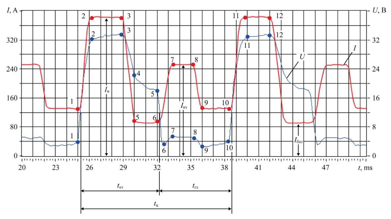
Fig. 4. Fragment of one cycle from the oscillogram of CMT process: mode parameters — in Figure 3
From the fragment of the oscillogram of one cycle (Fig. 4), it follows that at point (p.) 1, the process of interrupting the bridge starts at a relatively low current (135 A). This is much less than in the MIG/MAG process. The voltage drop on the interelectrode gap in 0.25 ms increases to the sum of the near-electrode voltage drops, and then, after 0.75 ms, increases to 32 V (p. 2), and the current increases to 380 A (p. 2) with a rate of increase of 250 kA/s.
The metal of the electrode wire, melted during the arc burning time in the time interval between p. 1 and p. 3 (about 4 ms) at a relatively high current value, is displaced from the electrode tip to its side surface. Then, within 1.0 ms, the current sharply decreases to the value of the base current (Iбаз — 90 A) at a rate of 290 kA/s, and the voltage decreases to 23 V. In the time interval of 2.0 ms (between p. 4 and p. 5), the length of the arc gap is reduced, and the voltage is decreased to 18 V. The value of the base current between p. 4 and p. 5 is automatically maintained constant by the source control system, the molten metal from the side surface of the electrode descends under its tip, takes the form of a spherical segment.
When the liquid metal of the spherical segment of the electrode comes into contact with the surface of the weld pool (p. 6 on the voltage curve), a reliable short circuit of the electric circuit occurs without splashing, which is observed during MIG/MAG surfacing, for 1 ms, and for 2 ms (between p. 7 and p. 8), the voltage drop on it is maintained constant (5 V), the current value is 250 A, respectively.
At p. 8, the servomotor is reversed, and the electrode starts moving in the opposite direction from the weld pool. The current value decreases to 130 A (p. 9) and remains unchanged for 2.5 ms (the interval between p. 9 and p. 10), and the voltage on the bridge increases by 1 V. At the same time, the bridge continues to be pulled out of the pool and narrows.
In p. 10, the bridge interrupts, the voltage on the arc gap becomes greater than the sum of its near-electrode drops, and the arc ignites. At the same time, the servomotor is reversed, and the electrode begins to flow toward the weld pool at an increased speed. Simultaneously, the voltage on the arc gap between p. 10 and p. 11 increases. This causes a high rate of current increase (480 kA/s) to a value of 380 A. In the time interval between p. 11 and p. 12, intensive melting of the electrode occurs, and the surfacing process cycle is repeated.
From the oscillogram data (Fig. 3 and Table 2), it follows that the CMT process is the most stable, since it has virtually no deviations — both in electrical and time parameters.
When surfacing a bead using the CMT process (Fig. 3), the current value during a short circuit of the arc gap, compared to the MIG/MAG process, at the same electrode feed rate, is lower, and the process is more stable and has a pronounced cyclic nature. The frequency of short circuits is higher, and the duration of the arc and the cycle time are shorter (Table 2). This contributes to a finer metal transfer, satisfactory formation of the surface of the surfacing bead with uniform scaling.
In the process of pulse surfacing (PulseSynergic), along with the use of the Synergic process itself, it is possible to cyclically alternate the energy parameters of the surfacing process. Due to such a pulsed change in the process current and arc voltage, the heat input in the weld pool is regulated, which, in turn, affects the geometrics of the surfacing bead.
The major task of pulsed arc surfacing (welding) with a consumable electrode with a long arc is to provide controlled fine-droplet transfer of metal in the region of modes with natural large-droplet transfer. The best process properties here are manifested when using spatially stable arcs, which are observed in a protective environment of argon or in a mixture with more than 80% Ar and CO2.
The section of the oscillogram of the PulseSynergic surfacing is shown in Figure 5. The parameters of the pulse surfacing process at different electrode feed rates are shown in Table 3, and the parameters of the rollers are shown in Table 4 (modes 9–11).
The current pulse has a trapezoidal shape, the amplitude of which is determined as Iи = Iп – Iбаз.
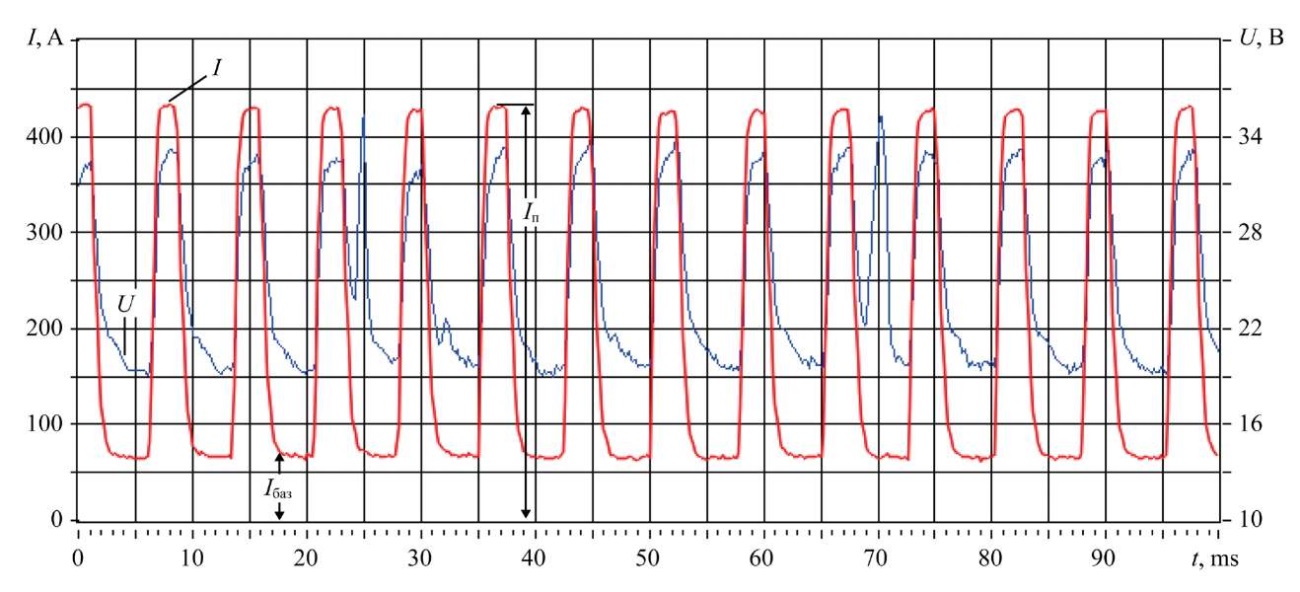
Fig. 5. Oscillogram of the pulse-arc process (PulseSynergic mode): surfacing mode parameter 10 in Table 3
Table 3
Parameters of Surfacing Modes by PulseSynergic Process
|
Mode no. |
Feed speed, νпп, m/min |
Process current value, A |
Voltage, V |
Duration, ms |
Current pulse frequency, 1/s |
Drop volume, mm³ |
||||
|
Iср |
Iбаз |
Iп |
Uп |
tИМ |
tп |
tц |
fИМП |
|||
|
9 |
5.0 |
157 |
45 |
430 |
24 |
3 |
7 |
10 |
100 |
1.19 |
|
10 |
6.5 |
192 |
70 |
430 |
24 |
3 |
5 |
8 |
125 |
1.11 |
|
11 |
8.0 |
233 |
100 |
430 |
26 |
3 |
3 |
6 |
166 |
1.15 |
The characteristic feature of the control algorithm of the surfacing process of the PulseSynergic mode is that the average process current (Iср) and its base current (Iбаз) are set by the electrode feed rate, and their values increase with an increase in the electrode feed rate. At the same time, the peak pulse current (Iп) and its duration (tИМ) remain unchanged, and the pause duration (tп) is reduced with a simultaneous increase in the pulse repetition frequency (fИМП), the volume of drops remains almost the same, fine-droplet (Table 3). Under such conditions, the surface of the deposited bead has a fine uniform scaly texture.
Table 4
Parameters of Beads Deposited by Different Processes
|
Mode no. |
Surfacing process |
Depth of penetration, a, mm |
Bead width е, mm |
Height of convexity, g, mm |
Penetration area, mm2 |
Surfacing area mm2 (calculation) |
Welding shape coefficient |
Form factor fusion |
Hardness HRC |
|
1 |
MIG/MAG |
2.4 |
8.8 |
3.2 |
10.0 |
20.0 |
2.8 |
3.7 |
21.0 |
|
2 |
3.0 |
10.7 |
3.2 |
15.0 |
24.5 |
3.3 |
3.6 |
24.0 |
|
|
3 |
3.3 |
14.5 |
2.9 |
21.0 |
29.4 |
5.0 |
4.4 |
18.5 |
|
|
4 |
Synergic |
2.3 |
9.2 |
2.9 |
9.2 |
18.2 |
3.2 |
4.0 |
29.0 |
|
5 |
1.2 |
10.1 |
3.6 |
4.0 |
26.0 |
2.8 |
8.4 |
24.0 |
|
|
6 |
4.0 |
14.4 |
3.0 |
22.0 |
30.0 |
4.8 |
3.6 |
19.0 |
|
|
7 |
CMT |
1.5 |
7.0 |
3.7 |
3.8 |
20.3 |
1.9 |
4.7 |
25.0 |
|
8 |
2.2 |
10.2 |
3.7 |
7.0 |
27.8 |
2.8 |
4.6 |
24.5 |
|
|
9 |
Pulse Synergic |
2.3 |
11.4 |
2.6 |
10.4 |
20.0 |
4.4 |
5.0 |
20.0 |
|
10 |
3.2 |
12.6 |
2.9 |
17.0 |
25.0 |
4.3 |
3.9 |
22.0 |
|
|
11 |
3.6 |
14.4 |
3.0 |
22.3 |
32.3 |
4.8 |
4.0 |
19.0 |
Note. The hardness of the plates made of steel 20 GOST 1050 was 10–12 HRC.
Table 4 shows the data on the geometric parameters of the beads deposited under the same conditions, at the same electrode feed rates. Based on these data, the dimensional characteristics of the beads were calculated (deposition shape coefficient kфн = e/g, penetration shape coefficient kфп = e/a, and deposition completeness coefficients μпн = Fн/(eg)), which characterize the completeness of filling a rectangle with the weld with dimensions е and g [8][15]. Based on these indicators, it can be concluded that it is advisable to weld the beads to create sealing surfaces for power engineering valves using a long arc through the PulseSynergic surfacing process, which provides stable electrical and time parameters that meet the welding and process properties of the surfaces under weld overlay.
Discussion and Conclusion. As a result of the conducted research, data were obtained that are of great importance for studying the influence of arc welding processes on the dimensions of deposited beads, on the hardness of sealing surfaces. The revealed patterns of changes in time of energy parameters of the surfacing mode with a short and long arc in the process of transferring electrode metal in the inter-arc gap can be taken into account when using low-inertia welding inverter power sources by specialists in their practical activities. The analysis of the modes of arc surfacing of beads with a consumable electrode in protective gases on the parts of the trim of power valves and the specific data obtained during it can be used in the further development of arc surfacing technologies and in future research on this topic. The selection of the gas-shielded arc welding process for sealing surfaces of power valves in favor of the PulseSynergic long arc welding process provides an opportunity to validate the minimization of electrical and time parameters of the welding process.
1. 2. Соколов Г.Н., Лысак В.И. Наплавка износостойких сплавов на прессовые штампы и инструмент для горячего деформирования сталей. Волгоград: ВолгГТУ; 2005. 284 с.
2. Sokolov GN, Lysak VI. Surfacing of Wear-Resistant Alloys on Press Dies and Tools for Hot Deformation of Steels. Volgograd: VolgGTU; 2005. 284 p. (In Russ.)
3. Stepin VS, Starchenko EG, Volobuev YuS, Egorov MYu. Modern Facing Materials for Sealing Surfaces of NPP and TPP Valves. Valve Industry. 2006;41(2):55–56. (In Russ.)
4. Erofeev VA, Zakharov SK, Kuznetsov OV. Features of Technology of Arc Surfacing Layers on the Steel Substrate. Izvestiya Tula State University. 2014;(11–1):132–138.
5. Sokolov GN, Zorin IV, Artem’ev AA, Elsukov SK, Dubtsov YuN, Lysak VI. Thermal- and Wear-Resistant Alloy Arc Welding Depositions Using Composite and Flux-Cored Wires with TiN, TiCN, and WC Nanoparticles. Journal of Materials Processing Technology. 2019;272:100–110. https://doi.org/10.1016/j.jmatprotec.2019.05.014
6. Eremin EN, Filippov YuO, Pokrovskiy DG, Losev AS, Eremin AE. Wear-Resistant Surfacing of Hot-Cutting Knives for Rolled Metal Products. Zagotovitel'nye proizvodstva v mashinostroenii. 2008;(4):17–19. (In Russ.)
7. Poloskov SS. Problems of Weld Overlay of Sealing Surfaces of Pipe Fitting and Solutions. Vestnik of Don State Technical University. 2019;19(4):349−356. https://doi.org/10.23947/1992-5980-2019-19-4-349-356
8. Elsukov SK. Improving the Efficiency of Two-Electrode Surfacing in Shielding Gases of Chromium-Nickel Austenitic Steels on Petrochemical Equipment Parts. Cand.Sci. (Eng.), diss. Volgograd; 2023. 143 p. (In Russ.)
9. Eremin AE, Filippov YuO, Matalasova AE, Kats VS. Structure and Properties of High Chromium Metal Valves Overlaid by Serially Produced Welding Wires Omsk Scientific Bulletin. 2014;127(1):55–58.
10. Rogozin DV, Lenivkin VA. Formation of a Technological Narrow-Band Weld Layer. Welding and Diagnostics. 2023;(5):49–54.
11. Kah P, Suoranta R, Martikainen J. Advanced Gas Metal Arc Welding Processes. International Journal of Advanced Manufacturing Technology. 2013;67:665–674. http://doi.org/10.1007/s00170-012-4513-5
12. Lenivkin VA, Dyurgerov NG, Sagirov KhN. Process Properties of Welding Arc in Shielding Gases. 2nd ed., enl. Moscow: NAKS; 2011. 368 p. (In Russ.)
13. Lenivkin VA, Rogozin DV. Types of Self-Regulation of Consumable Arc Welding Processes. Welding and Diagnostics. 2021;(1):53–60. (In Russ.) https://doi.org/10.52177/2071-5234_2021_01_53
14. Potap'evskii AG. Gas-Shielded Welding with a Consumable Electrode. Part 1. Active Gas Welding. 2nd rev. ed. Kiev: Ekotekhnologiya; 2007. 192 p. (In Russ.)
15. Milyutin VS, Kataev RF. Welding Properties of Arc Welding Equipment. Moscow: NAKS media; 2016. 457 p. (In Russ.)
Dmitrii V. Rogozin, Cand.Sci. (Eng.), Associate Professor of the Welding Fabrication Machines and Automation Department
1, Gagarin Sq., Rostov-on-Don, 344003
Vyacheslav A. Lenivkin, Dr.Sci. (Eng.), Leading Researcher at the Scientific Competence Center
1, Gagarin Sq., Rostov-on-Don, 344003
Rogozin D.V., Lenivkin V.A. Selection of the Process of Arc Welding of Sealing Surfaces of Power Valves with a Consumable Electrode in the Shielding Gas. Advanced Engineering Research (Rostov-on-Don). 2024;24(4):402-412. https://doi.org/10.23947/2687-1653-2024-24-4-402-412. EDN: TKWDZL


Advanced Engineering Research (Rostov-on-Don)
ISSN 2687-1653 (Online)
Contact with: Publisher / Editorial Office of the Journal
Publisher: Don State Technical University - DSTU, Rostov-on-Don, Russia - https://donstu.ru/en/
Editor-in-Chief: Alexey N. Beskopylny, Dr.Sci. (Eng.), Professor, Vice-Rector, Don State Technical University (Rostov-on-Don, Russia)
Don State Technical University
1, Gagarin Sq., Rostov-on-Don, 344003, Russia
tel.: +7 (863) 2738-372, e-mail: vestnik@donstu.ru
16+
Processing of personal data