


Contents
Scroll to:
https://doi.org/10.23947/2687-1653-2025-25-1-14-22
EDN: YINENP
Scroll to:
Introduction. Walking robots are widely used in industry due to their unique capabilities for moving on uneven and complex surfaces. To provide high precision in controlling their movement, it is required to develop mathematical models and algorithms for planning the robot movement along various trajectories. A key aspect of the motion control system of walking robots is the planning of their leg movements. Despite significant advances in the field of modeling the kinematics of quadruped robots, existing scientific publications do not provide a complete kinematic model for robots similar to the Mini Cheetah. This research was aimed at the development of a kinematic model of a quadruped robot based on Mini Cheetah, as well as the formulation of recommendations for optimizing its gait to provide rotation around various axes. The creation of such a model will improve the smoothness and accuracy of the robot movements, which, in turn, will increase its efficiency under real production conditions.
Materials and Methods. The process of constructing a kinematic model of the robot was based on the use of formulas for the geometry of spatial motion of solids. To test the efficiency of the proposed algorithms for moving the robot legs when performing rotational movements of its body, numerical modeling of the robot kinematics was used. Numerical calculations were performed using the Wolfram Mathematica package.
Results. The laws of changing the endpoints of the robot legs during its rotation around the vertical axis were proposed. The conducted numerical modeling of the robot kinematics covered the rotation of the body at the course, roll and pitch angles. Based on the simulation results, it was established that the dependences of the rotation angles of the leg links were periodic functions. The considered rotational movements of the robot platform could take place without the occurrence of singular configurations.
Discussion and Conclusion. The results of numerical modeling of the robot platform rotation movements confirmed the operability of the proposed leg transfer plan, which allowed for smooth movement of the robot body and avoidance of singular configurations. The resulting kinematic model can be used to control the robot motion at the kinematic level when moving along curvilinear trajectories. As a prospect for further research, it is worth highlighting the development of a mathematical model of the dynamics of a four-legged robot, as well as the creation of laws for controlling its movement at a dynamic level. This will significantly expand the functionality of the robot and increase its efficiency under various operating conditions.
Fernando M.J., Saypulaev G.R., Saypulaev M.R. Analysis of a Four-Legged Robot Kinematics during Rotational Movements of Its Body. Advanced Engineering Research (Rostov-on-Don). 2025;25(1):14-22. https://doi.org/10.23947/2687-1653-2025-25-1-14-22. EDN: YINENP
Introduction. Currently, walking mobile robots are widely used to solve problems of observation and exploration of territories [1]. An example of one of the common designs of such robots is the four-legged robot Mini Cheetah (Fig. 1), developed at MIT Biomimetic Robotics Lab (https://biomimetics.mit.edu). These four-legged robots can move on various types of terrain, unlike wheeled or tracked robots.
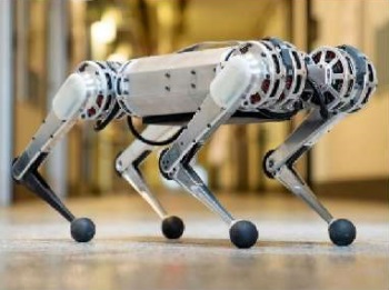
Fig. 1. Four-legged robot Mini Cheetah1
The design of the walking robots under consideration includes a platform to which four legs are attached. Each of the legs is a three-link manipulator. One of the key aspects of a walking robot is the topology of its leg structure [2][3]. The topology of the legs refers to the composition and arrangement of the links, as well as the hinges of the limbs of a four-legged robot, which play an important role in providing its movement and stability. The development of an optimal topology for the leg structure of quadruped robots is one of the challenges in engineering. The solution to this problem not only helps to provide stable and efficient gait (locomotion) of the robot on various surfaces, but also makes its mechanical design more reliable and energy efficient.
Another aspect that needs to be considered is the drive system applied in quadruped robots [4]. Different types of drives are widely used in such robots, including pneumatic [5], hydraulic [6][7], and electric [2][6], each of which has its own advantages and disadvantages.
Four-legged robots have complex kinematics due to a large number of degrees of freedom. The robot considered in this paper has 18 degrees of freedom. To provide successful locomotion of four-legged robots, it is necessary to solve both direct and inverse problems of kinematics, which allows organizing dynamic control of the position of the legs of these robots. This control should provide the robot balancing, the ability to overcome various surfaces, and adaptation to various types of locomotion, including walking, running and jumping. The direct problem of walking robot kinematics is to determine the position and orientation of the robot platform based on the known rotation angles of the leg links. The inverse problem is to find the rotation angles of the leg links that provide a given position and orientation of the robot platform.
Paper [8] described in detail the application of the Denavit-Hartenberg method for modeling the forward and inverse kinematics of a walking robot. The study on the kinematic model of the robot was conducted with the aim of creating a gait algorithm.
The authors of [9] developed advanced kinematic and dynamic modeling methodologies based on the screw theory for quadruped robots. The proposed methods accounted for different gaits and leg mechanism topologies using simplified models of foot contact (e.g., a ball-and-socket model). Models were described for three separate phases of robot motion: standing, walking, and unsupported (flying) phase. The developed control strategies used the presented models for gait planning and jogging.
In recent years, scientists have been working on control and trajectory planning systems. The motion control method is the basis of a four-legged robot, directly affecting flexibility, stability and the ability to adapt to various support surfaces [3].
The authors of [10] specified the design of a regulator for the force control of a four-legged robot. The main purpose of the regulator was to equalize the forces acting on the robot during symmetrical gait, as well as to reduce disturbances and absorb impacts.
In [11], a new motion control strategy for a quadruped robot that enabled it to navigate efficiently on uneven terrains regardless of visual perception conditions was proposed. Paper [12] discussed the design of a motion controller for a quadruped robot that used torque optimization and performance control to account for the impact of unpredictable external forces such as surface irregularities.
Experimental studies devoted to the application of hierarchical controllers for motion control of quadruped robots were presented in [13], illustrated by the ANYmal robot, and in [14], exemplified by the StarlETH robot.
In [15], the authors discussed the development of a quadruped robot designed for construction and emergency response tasks. Their paper examined the statics, kinematics, and control system for the specific design of this robot.
Finally, in [16], a new central pattern generator model controller and gait switching tactic based on the Wilson-Cowan model were presented. This development aimed to create a smooth robot gait and reduce the adjustment time in the oscillating mechanical system.
Despite the development of the problem of modeling the kinematics of quadruped robots, in existing publications there was no complete kinematic model of the motion of robots whose leg design was similar to the Mini Cheetah robot (Fig. 1). Therefore, the objective of this work was to develop a kinematic model of a quadruped robot using the example of the Mini Cheetah and to develop proposals for planning the movements of the robot links that could provide the rotation of the robot around various axes.
To achieve the stated goal, we needed to formulate the laws of change of coordinates of the endpoints of the robot legs and angular coordinates of its body. It was also necessary to solve the inverse problem of robot kinematics to check the operability of the proposed motion plan. The results obtained can be used to develop robot control at the kinematic level.
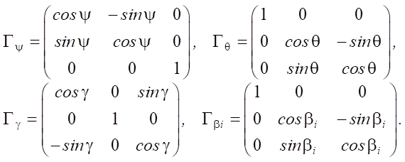
Materials and Methods. System Definition. The object of the study is a robotic system consisting of a rigid body (robot platform) and four legs with three degrees of freedom for each of the legs. The links of the legs are connected to the robot platform by several hinges, which are driven by electric drives. Angle βi is the angle of rotation of link OiAi around the longitudinal axis of the robot body and characterizes the rotation of the plane of the leg (containing points Ai, Bi, Ki) relative to the vertical plane of symmetry CXZ. And angles αi, βi characterize the rotation of links AiBi and BiKi in the plane of the leg. The hinges of the leg links at points Oi, Ai, Bi are controlled, i.e., the rotation of the leg links at angles φi, αi, βi is provided independently by the corresponding drives.
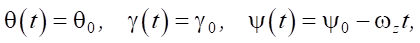
Fixed coordinate system XYZ and moving coordinates Cxyz are introduced, where point C is the geometric center of the robot platform (Fig. 2 a). The orientation of the robot platform is described by course angles ψ (rotation around axis z), roll θ (rotation around axis x) and pitch γ (rotation around axis y), and the position of the robot platform is determined by the coordinates of the geometric center xC, yC and zC in the fixed coordinate system.
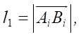
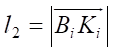
The distances along the longitudinal and transverse axes of the robot platform from the center of mass C and the attachment points of the legs to the robot platform Oi in the moving axes xiyizi are specified by ρxi and ρyi. The lengths of the links are designated as  ,
, 
 (Fig. 2 b).
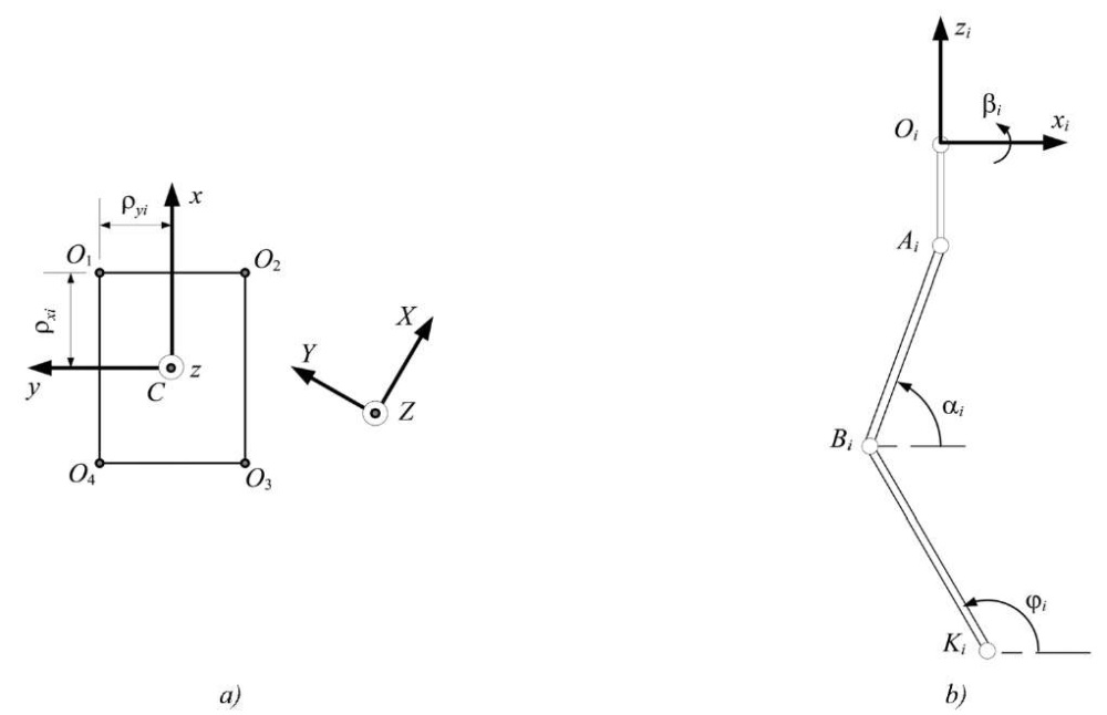
Fig. 2. Kinematic diagram of the robot:
a — top view of the robot body; b — side view of the robot leg
In projections onto the axes of the fixed coordinate system XYZ, the position vector of the endpoint of the leg Ki (or the point in contact with the surface) is determined from the formula:
 (1)
(1)
where  — position vector of the geometric center of the robot platform C; Гψγθ = ГψГθГγ — rotation matrix, which is calculated as the product of the elementary rotation matrices by the course, roll, and pitch angles. The rotation matrices included in equation (1), have the form:
 (2)
(2)
Other radius vectors included in equation (1) are determined from the expressions:
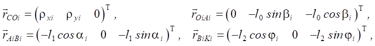 (3)
(3)
here, the superscript “T” means the vector transpose operation.
After performing intermediate calculations on the right side of equation (1), taking into account expressions (2) and (3), we obtain projections of the position vector rKi for each leg.
Differentiating equation (1) with respect to time, we obtain a kinematic model in the form:
 (4)
(4)
where 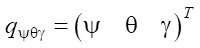 — vector of angular generalized coordinates of the robot platform;
 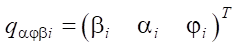 — vector of angular generalized coordinates of the robot leg links;
  — vector of linear velocity of the endpoint of the i-th leg;
  — vector of linear velocity of the geometric center of the robot platform;
  — matrices of coefficients for the corresponding vectors of generalized velocities.
Research Results. To analyze the rotational motions of the robot by solving the equations of motion geometry (1) (or integrating the kinematic equations (4)), we set the initial conditions for the rotation angles of the leg links and the laws of change in the velocities of the endpoints of the legs vKi, the geometric center of the robot platform vC and the vector of angular generalized coordinates qψθγ. Considering the rotational movements of the robot platform, we assume that the geometric center is stationary during the movement vC = 0.
As the initial position of the leg links, we take the following angle values φi, αi, βi for each of the legs:
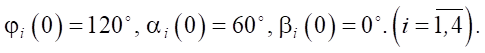 (5)
(5)
The given combination of angle values φi, αi, βi corresponds to the robot standing on semi-bent legs, which is presented in a simplified visualization (Fig. 3) made in Wolfram Mathematica. The following values of the robot geometric parameters were used in the visualization: l0 = 0.15 m, l1 = 0.45 m, l2 = 0.45 m, ρx1 = ρx2 = –ρx3 = –ρx4 = 0.5 m, ρy1 = –ρy2 = –ρy3 = ρy4 = 0.25 m.
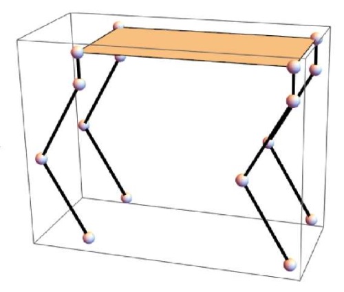
Fig. 3. Simplified visualization of the robot initial position
To perform periodic rotary movements of the robot platform, limited only by the roll angle, we set the laws for changing the orientation angles of the platform in the form:
 (6)
(6)
where ψ0 = 0°, θ0 = 0°, γ0 = 0° — initial values of orientation angles; A = 0.2 rad and Т = 20 s — constants characterizing the amplitude and period of oscillations by angle. Since it is optional to move the legs when the robot platform is rotated along the roll angle, the coordinates of the contact points of the legs with the support surface remain unchanged (vKi = 0):
 , (7)
, (7)
where xKi(0) and yKi(0) — initial coordinates of the contact points of the robot legs with the support surface.
Solving equations (1) with respect to (2) and (3), when substituting the program motion (6) and (7), we obtain the dependences of the rotation angles φi, αi, βi of the leg links (Fig. 4).
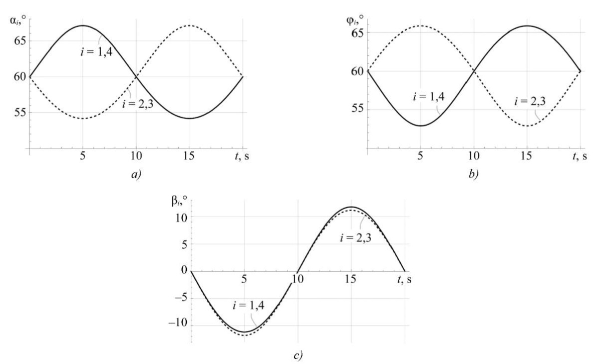
Fig. 4. Roll angle turn simulation results:
a — angles αi(t); b — angles φi(t); c — angles βi(t)
According to the results of the simulation presented in Figure 4, it can be noted that the rotation angles of the leg links are harmonic functions. As a consequence, it can be mentioned that the rotations of the robot platform around the longitudinal axis of symmetry of the robot (6) can be performed without tearing the contact points of the legs from the surface.
To perform periodic rotary movements of the robot platform, only in pitch angle, we set the laws for changing the orientation angles of the platform in the form:
 (8)
(8)
When the robot platform rotates along the pitch angle, the transfer of the legs is optional, and the coordinates of the points of contact of the legs with the supporting surface remain unchanged.
Solving equations (1) taking into account (2) and (3), and substituting program movements (7) and (8), we obtain the dependences of the rotation angles φi, αi, βi of the leg links (Fig. 5).
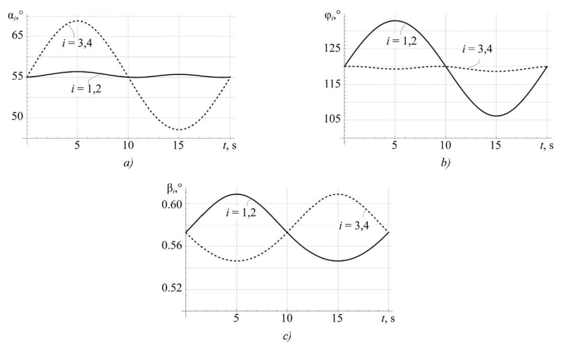
Fig. 5. Pitch angle turn simulation results:
a — angles αi(t); b — angles φi(t); c — angles βi(t)
According to the simulation results presented in Figure 5, it can be noted that the rotation angles of the leg links are harmonic functions. As a consequence, it can be mentioned that the rotations of the robot platform around the transverse axis of symmetry of the robot (8) can be performed without tearing the contact points of the legs from the surface.
To perform rotation around axis Z, we consider the laws of changing the orientation angles of the robot platform in the form:
 (9)
(9)
where ωz = 0.085 rad/s angular velocity of rotation of the robot platform.
To provide the rotation of the robot around the vertical axis, it is required to plan the movement of the legs. Let us consider the case when the trajectories of the contact points of the legs in projections onto the horizontal plane XY belong to a circle of radius ρ. In this case, we will assume that the axis, around which the rotation of the robot platform occurs, passes through the geometric center of the platform. Then, the expressions for the coordinates of the endpoints of the legs can be determined from the relations:
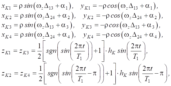 (10)
(10)
where 
 — angle characterizing the position of the endpoint of the i-th leg at the initial moment of time; hK = 0.3 m — maximum height to which the endpoints of the robot legs rise; T1 = 6 s — time of one step; Δ13, Δ24 — auxiliary functions used to provide a piecewise assignment of the change in the coordinates of the endpoints of the legs:
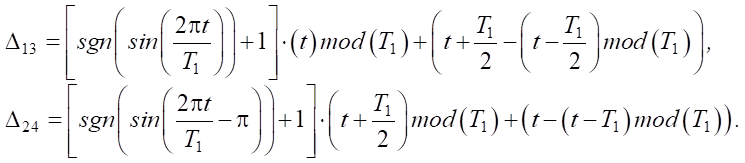 (11)
(11)
Here, function (t)mod(T1) returns the remainder of the integer division t by T1. The piecewise character of the coordinate change assignment is associated with the consideration of gaits (elementary leg movements), in which a sequential transfer of the crossed legs is performed.
Solving equation (1) with respect to (2) and (3), when substituting the program movement (9)–(11), we obtain the dependences of the rotation angles φi, αi, βi of the leg links (Fig. 6).
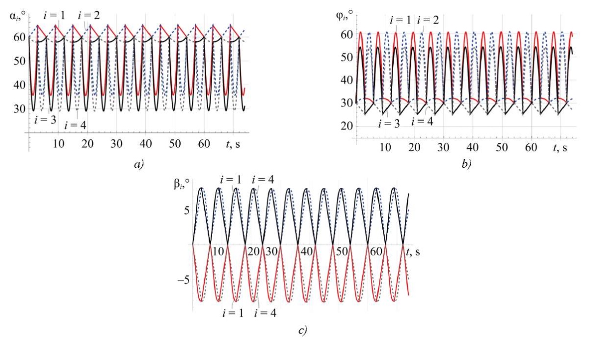
Fig. 6. Course angle turn simulation results:
a — angles αi(t); b — angles φi(t); c — angles βi(t)
The simulation results show that the dependences of the rotation angles of the leg links are periodic functions and, as a consequence, the considered rotational movements of the robot platform can take place without the occurrence of singular configurations. Thus, the proposed plan for transferring the legs (10), (11) during rotation around vertical axis Z is suitable for implementing the rotation of the robot at an arbitrary angle ψ.
Discussion and Conclusion. The constructed mathematical model of kinematics allows for the determination of the angles in the joints of the robot leg links, which must be provided to implement the desired movement of the robot platform. The obtained results of numerical modeling of the rotary movements of the robot body confirmed the operability of the developed kinematic model for assessing the implementation of the specified robot movements, taking into account the limitations and dimensions of the structure.
In cases where the robot platform performs a flat motion (at zero pitch and roll angles), the constructed mathematical model of kinematics coincides with the published results of other authors. The results obtained in this paper are a generalization and refinement of the equations that couple the rotation angles of the robot leg links with the position and orientation of the robot platform.
The application of the developed kinematic model (1), (4), as well as the proposed plan for transferring legs (10), (11) during rotation around the vertical axis, will allow constructing control at the kinematic level for the robot movement along curvilinear trajectories. This approach will significantly expand the robot functionality and increase its performance efficiency under various operating conditions.
1. Massachusetts Institute of Technology . URL: https://news.mit.edu/2019/mit-mini-cheetah-first-four-legged-robot-to-backflip-0304 (accessed: 07.11.2024).
1. Pavlovsky VE. For Elaboration of Walking Machines. Keldysh Institute Preprints. 2013;(101):1–32. URL: https://keldysh.ru/papers/2013/prep2013_101.pdf (accessed: 20.11.2024).
2. Taheri H, Mozayani N. A Study on Quadruped Mobile Robot. Mechanism and Machine Theory. 2023;190:105448. https://doi.org/10.1016/j.mechmachtheory.2023.105448
3. Hui Chai, Yibin Li, Rui Song, Guoteng Zhang, Qin Zhang, Song Liu, et al. A Survey of the Development of Quadruped Robots: Joint Configuration, Dynamic Locomotion Control Method and Mobile Manipulation Approach. Biomimetic Intelligence and Robotics. 2022;2(1):100029. https://doi.org/10.1016/j.birob.2021.100029
4. Liang ZJ, Jiang L, Zhao JX, Xing BY, Xu P, Su B. Design and Analysis of High Dynamic Actuator and Implementation on Quadruped Robot. Journal of Physics: Conferences Series. 2023;2478:102002. https://doi.org/10.1088/1742-6596/2478/10/102002
5. Jiupeng Chen, Hongjun San, Xing Wu. Gait Regulation of a Bionic Quadruped Robot with Antiparallelogram Leg Based on CPG Oscillator. Complexity. 2019;2019(5):5491298. https://doi.org/10.1155/2019/5491298
6. Khan H, Kitano S, Frigerio M, Camurri M, Barasuol V, Featherstone R, et al. Development of the Lightweight Hydraulic Quadruped Robot — MiniHyQ. In: Proceedings of the 2015 IEEE International Conference on Technologies for Practical Robot Applications (TePRA). New York City: IEEE; 2015. P. 1–6. https://doi.org/10.1109/TePRA.2015.7219671
7. Lizhou Fang, Junhui Zhang, Huaizhi Zong, Ximeng Wang, Kun Zhang, Jun Shen, et al. Open-Source Lower Controller for Twelve Degrees of Freedom Hydraulic Quadruped Robot with Distributed Control Scheme. HardwareX. 2023;13:e00393. https://doi.org/10.1016/j.ohx.2022.e00393
8. Yunde Shi, Shilin Li, Mingqiu Guo, Yuan Yang, Dan Xia, Xiang Luo. Structural Design, Simulation and Experiment of Quadruped Robot. Applied Sciences. 2021;11(22):10705. https://doi.org/10.3390/app112210705
9. Wei Yan, Yang Pan, Junjie Che, Jiexian Yu, Zhuchen Han. Whole-Body Kinematic and Dynamic Modeling for Quadruped Robot under Different Gaits and Mechanism Topologies. PeerJ Computer Science. 2021;7(1):e821. https://doi.org/10.7717/peerj-cs.821
10. Havoutis I, Semini C, Buchli J, Caldwell DG. Quadrupedal Trotting with Active Compliance. In: Proceedings of the 2013 IEEE International Conference on Mechatronics (ICM). New York City: IEEE; 2013. P. 610–616. https://doi.org/10.1109/ICMECH.2013.6519112
11. Jiawei Chen, Kun Xu, Xilun Ding. Adaptive Gait Planning for Quadruped Robot Based on Center of Inertia over Rough Terrain. Biomimetic Intelligence and Robotics. 2021;2(1):100031. https://doi.org/10.1016/j.birob.2021.100031
12. Guiyang Xin, Wolfslag W, Hsiu-Chin Lin, Tiseo C, Mistry M. An Optimization-Based Locomotion Controller for Quadruped Robots Leveraging Cartesian Impedance Control. Frontiers in Robotics and AI. 2020;7:48. https://doi.org/10.3389/frobt.2020.00048
13. Bellicoso CD, Gehring C, Hwangbo J, Fankhauser P, Hutter M. Perception-less Terrain Adaptation through Whole Body Control and Hierarchical Optimization. In: Proceedings of the 2016 IEEE-RAS 16th International Conference on Humanoid Robots (Humanoids). New York City: IEEE; 2017. P. 558–564. https://doi.org/10.1109/HUMANOIDS.2016.7803330
14. Hutter M, Sommer H, Gehring C, Hoepflinger M, Bloesch M, Siegwart R. Quadrupedal Locomotion Using Hierarchical Operational Space Control. The International Journal of Robotics Research. 2014;33(8):1047–1062. https://doi.org/10.1177/0278364913519834
15. Zhao Z, Noritsugu T, Takaiwa M, Sasaki D. Development of Quadruped Robot with Pneumatic Actuator. In: Proceedings of the 8th International Symposium on Fluid Power. New York City: IEEE; 2010. P. 325–330. https://doi.org/10.1299/jsmeicam.2010.5.325
16. Junmin Li, Jinge Wang, Simon X Yang, Kedong Zhou, Huijuan Tang. Gait Planning and Stability Control of a Quadruped Robot. Computational Intelligence and Neuroscience. 2016:2016;9853070. https://doi.org/10.1155/2016/9853070
Marcelino J. Fernando, student of the Department of Robotics, Mechatronics, Dynamics and Strength of Machines
Scopus ID: 59000562600
14, Krasnokazarmennaya Str., Moscow, 111250
Gasan R. Saypulaev, Cand.Sci. (Eng.), Senior Lecturer of the Department of Robotics, Mechatronics, Dynamics and Strength of Machines
Scopus ID: 57222571340
14, Krasnokazarmennaya Str., Moscow, 111250
Musa R. Saypulaev, Cand.Sci. (Eng.), Senior Lecturer of the Department of Robotics, Mechatronics, Dynamics and Strength of Machines
Scopus ID: 57382428600
14, Krasnokazarmennaya Str., Moscow, 111250
Fernando M.J., Saypulaev G.R., Saypulaev M.R. Analysis of a Four-Legged Robot Kinematics during Rotational Movements of Its Body. Advanced Engineering Research (Rostov-on-Don). 2025;25(1):14-22. https://doi.org/10.23947/2687-1653-2025-25-1-14-22. EDN: YINENP


Advanced Engineering Research (Rostov-on-Don)
ISSN 2687-1653 (Online)
Contact with: Publisher / Editorial Office of the Journal
Publisher: Don State Technical University - DSTU, Rostov-on-Don, Russia - https://donstu.ru/en/
Editor-in-Chief: Alexey N. Beskopylny, Dr.Sci. (Eng.), Professor, Vice-Rector, Don State Technical University (Rostov-on-Don, Russia)
Don State Technical University
1, Gagarin Sq., Rostov-on-Don, 344003, Russia
tel.: +7 (863) 2738-372, e-mail: vestnik@donstu.ru
16+
Processing of personal data


