


Contents
Scroll to:
https://doi.org/10.23947/2687-1653-2025-25-3-256-268
EDN: PWKCXM
Scroll to:
Introduction. The BPMN standard system (notation) is widely used in business process modeling. However, it is not expressive enough to represent technical and production mechanisms. BPMN poorly describes parallel flows with strict resource constraints, insufficiently supports modeling of physical parameters and technological conditions. These and other shortcomings worsen the analysis of performance and reliability, reduce the applicability of models for optimization and verification. The objective of the presented work is to create a method that uses an alternative notation and thus limits the impact of the listed shortcomings of BPMN in modeling production processes.
Materials and Methods. The basis of the new solution was a comparison of BPMN and the notation for the system “node – function – object” (NFO). The elements of the diagrams were the intersections of some connections (nodes). They contained functional elements (functions, processes), which in some cases also had the characteristics of a substance (objects). A comparative analysis of the normative systems of BPMN and NFO showed the possibility of mutual transformation of diagrams. The processes were visualized using the CASE (Computer Aided Software Engineering) tool NFO-toolkit and the Stormbpmn program according to the BPMN rules. The NFO diagram was described in the XPDL2 language.
Results. Six sequential operations have been developed for converting a NFO diagram into BPMN, and four — for the reverse transformation. The scheme of component production is shown in the context and decomposition, from the requirement for the development of the workflow to the issuance of products. Decompositions of the NFO elements “Injection Molding Machine”, “Master” and “Development Department” are presented, each of which corresponds to a decomposition of the same-name track of the BPMN notation pool. It has been proven that converting a BPMN diagram to a NFO improves the description of the process as a whole and to any degree of detail. The NFO approach does not refer to the graphical notation system of BPMN, which increases labor costs and the risk of simulation errors. The XPDL language describes processes, connectors, splitters, relationships, external entities, and other elements of NFO diagrams.
Discussion. The main advantages of NFO notation over the BPMN approach are: easier procedure for creating models and their better visualization. A simple graphic set of NFO reduces simulation time and increases its accuracy. The NFO approach is focused on taking into account information and material connections. This means that it is possible to conduct functional cost CASE analysis, which is impossible using the BPMN method. The XPDL language is suitable for describing elements of NFO diagrams, and the solution can be Russified.
Conclusion. Content redundancy and other shortcomings of the BPMN notation are eliminated through using a more universal and convenient notation — NFO. The research results will contribute to the development of the theory and practice of graphanalytic modeling of production processes, and simplify the procedure for their development and automation.
Zhikharev A.G., Malkush E.V., Matorin S.I. Improving Business Process Model and Notation Diagrams with the Node-Function-Object Approach. Advanced Engineering Research (Rostov-on-Don). 2025;25(3):256-268. https://doi.org/10.23947/2687-1653-2025-25-3-256-268. EDN: PWKCXM
Introduction. Information systems and technologies provide automation of processing and production, which is essential for the modern economy [1]. Thus, in 2024, the analytical portal IaaSSaaSPaaS reported that BPM (Business Process Management) systems are used in Russia by about 12,000 organizations, and hundreds of IT companies are engaged in the implementation1.
An integral part of the procedure for creating such solutions is the formulation of requirements for them. This is an important element of design [2], which is based on modeling and analysis of automated processes [3]. The analysis is performed using both mathematical tools and graphical notations (IDEF, DFD, EPC, BPMN families, etc. [4]). Each of the listed groups has its own characteristics [5], which are assessed differently by researchers and users [6].
One of the most popular notations is BPMN specification (Business Process Model and Notation)2. According to the statistical report of the company “Business Logic”, BPMN is widely used to describe business processes and occupies more than half of the market — 54% [7]. This particular notation is recommended to be used, e.g., in [8]. At the same time, BPMN has significant disadvantages3, and they have been repeatedly discussed in the literature. Some of them are listed below:
Business process modeling experts admit that such shortcomings often cause errors when constructing diagrams in BPMN notation. Diagrams can be incomprehensible. This complicates the interaction between developers and can cause the design deadlines to be missed4,5. There have even been proposals to abandon BPMN. The author of one such work6 claims that the notation in question has no particular advantages. He compares BPMN to a cargo cult, i.e., mechanical copying of actions without understanding the essence of the processes. It is noted that the system was proposed not by business practitioners, but by software developers.
BPMN has integrated tools for translating diagrams into business process execution languages (e.g., XPDEL) [12], and the literature contains recommendations for converting other notations into BPMN. Thus, in [13], IDEF0 is considered from this point of view.
Therefore, the shortcomings of BPMN are known and widely discussed, but there are no constructive suggestions for overcoming them in the public domain. The presented study is intended to fill this gap. The objective of this work is to create alternative, more universal notations that will reduce the impact of the above-mentioned shortcomings of BPMN in modeling production and processing. First of all, it is necessary to solve problems related to the difficulties of modeling and reading diagrams.
Materials and Methods. The authors [14] investigated graph-analytic notations as normative systems. In this sense, the notation of the system-object approach “node – function – object” (NFO approach) turned out to be more universal in comparison with other graphic notations. In this case, universality is provided by the representation of any system in the form of an element “node – function – object” [10], for which the following statements are true.
Node — a structural element of a supersystem. It represents a crossroad of connections (flows of transmitted elements) of a system with other systems in this supersystem.
Function — a functional element. It performs a certain role to support the supersystem through balancing a given node (transforming input flows into output flows).
Object — a substantial element. This function is implemented in the form of a certain material formation that has design, operational and other characteristics.
The content classification of connections as flows of elements assumes two levels. In material connections, there are substantial (S) and energy (E). In information connections, there are data (D) and control (C) connections.
The analysis of existing graphic notations shows that their alphabet and, accordingly, diagrams, are intersections of connections in which functional elements are located, which in some cases have the characteristics of a substance. Thus, all alphabetic elements of all graphic notations are nodes with functions and often with object characteristics. This allows us to consider the notation of the NFO approach, i.e., NFO notation as universal [14].
The following are the correspondences between BPMN and NFO notations. They are found during comparative analysis and will be the basis for solving the problems of diagram transformations and their evaluation.
For visualization, we use the CASE tool (Computer Aided Software Engineering) NFO-toolkit and the Stormbpmn program in accordance with the BPMN rules.
Thus, according to the stated research objective, we use the listed materials and methods to assess the potential of transforming NFO diagrams into BPMN diagrams and vice versa. Let us consider the possibility of full replacement of BPMN diagrams with NFO diagrams. We find out, firstly, to what extent the NFO approach is able to eliminate the shortcomings of BPMN diagrams. Secondly, we study the task of describing NFO diagrams in the XPDL language7.
Research Results. To implement the tasks and goals of the work, we simulate a production situation: we show a diagram of the interaction of departments associated with the component release.
Converting NFO diagram to BPMN. Converting diagrams in system-structural notations (particularly, in DFD and IDEF0) to NFO diagrams does not require the development of a specific procedure. NFO diagram in which NFO elements are functional nodes (without defining objects) is equivalent to DFD diagram. NFO diagram in which NFO elements are defined to the object level and there is no relationship “Mechanism” is equivalent to IDEF0 diagram. Thus, for the situation under consideration, instead of developing recommendations for converting various notations into BPMN, a method for converting NFO diagrams into BPMN is needed. This transformation is provided through performing six operations, which are described below. The correspondence of BPMN elements and NFO is given in the Materials and Methods section. The logical operation sign “®” (implication) means replacing the object to the left of the sign with the object to the right of it.
1. Context NFO diagram is converted to BPMN pool.
1.1. Context NFO element as a process or object ® open BPMN diagram pool.
1.2. External entities of the context NFO diagram ® closed BPMN diagram pools.
1.3. Functional (external) relationships of the context NFO element as a process or object that are not related to external entities (or it is not practical to show these entities) ® start or end events in the open BPMN pool.
2. Processes on decomposition of the context object of NFO diagram are transformed into BPMN subprocesses or into pool tracks .
2.1. Processes on decomposition of context NFO element as a process or object ® BPMN subprocesses, if the open pool has one track.
2.2. Processes on decomposition of context NFO element as a process or object ® tracks of the open BPMN pool, if the open pool has several tracks.
3. NFO diagram relationships are converted into BPMN diagram relationships.
3.1. Information relationships (flows) according to NFO diagram data ® BPMN message flows or data objects.
3.2. Information relationships (flows) according to NFO diagram control ® BPMN operation flows.
3.3. Material relationships (flows) of NFO diagram ® BPMN operation flows with corresponding names.
4. Multiple input and output relationships of NFO elements as processes are connected to BPMN subprocesses via gateways .
4.1. If NFO element has several input arrows, they are connected through a gateway whose logical function is determined by the value of the input connections.
4.2. If NFO element has several output arrows, they exit through a gateway whose logical function is determined by the value of the output connections.
5. If NFO elements corresponding to the subprocesses are decomposed, then the processes in these decompositions ® BPMN tasks.
6. Markers corresponding to the names of the relationships are installed on the relationships, if this makes sense.
Figures 1–3 show an example of converting NFO diagram into BPMN diagram using the procedure presented above. The NFO diagrams (Fig. 1 and 2) were created using the CASE tool NFO-toolkit, and the BPMN diagram (Fig. 3) was created using the Stormbpmn program in accordance with the BPMN rules.
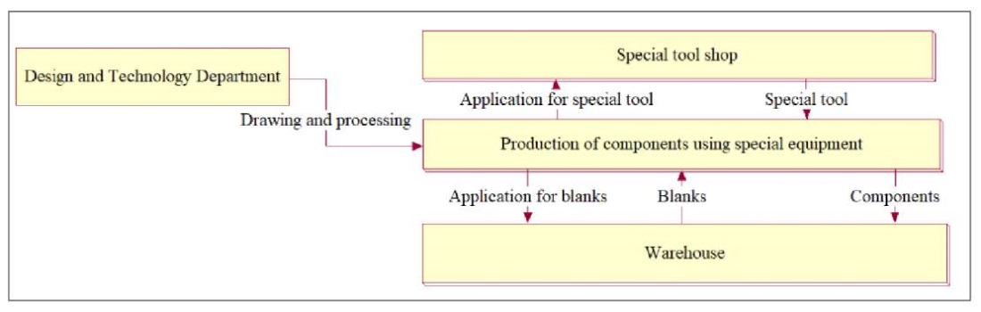
Fig. 1. Context NFO diagram
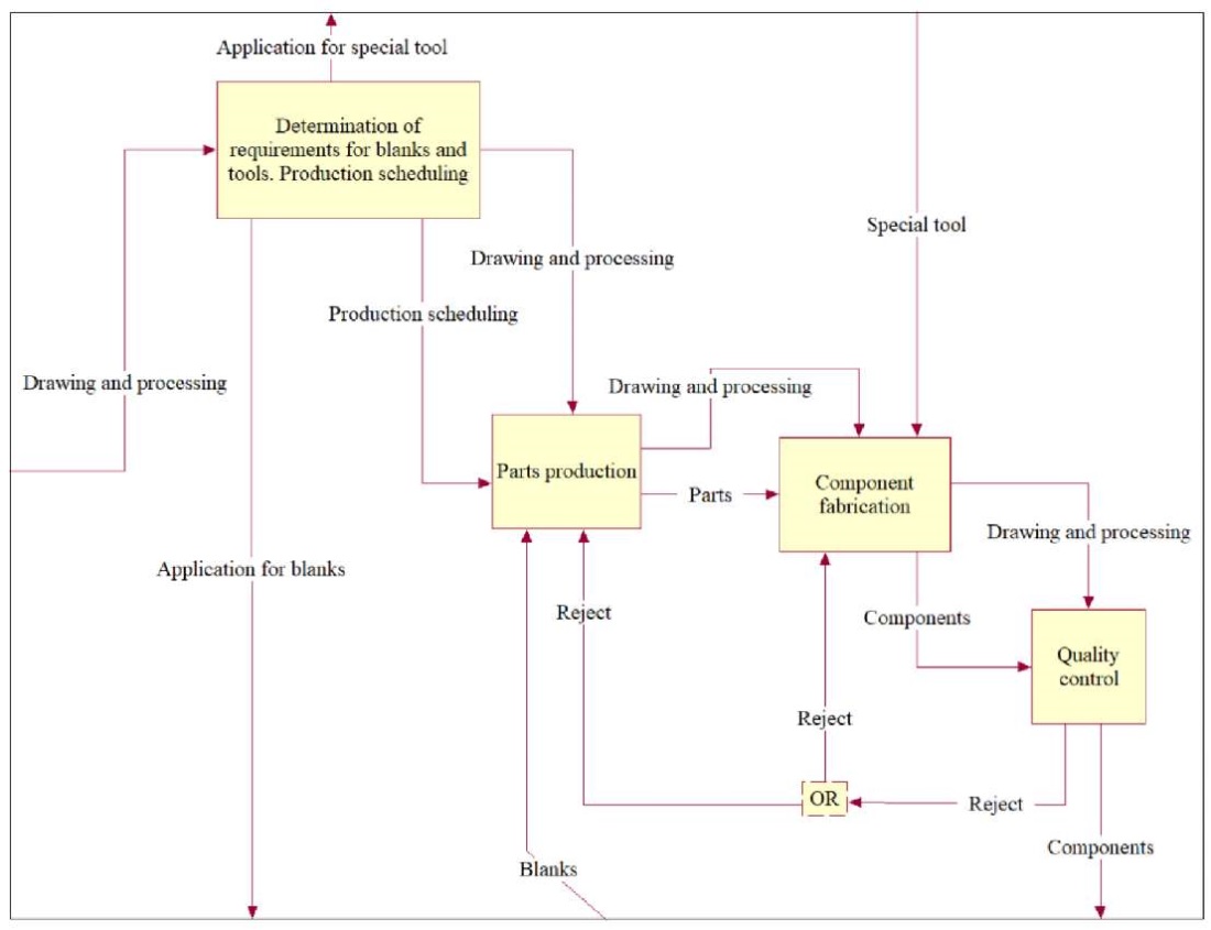
Fig. 2. Decomposition of context NFO diagram
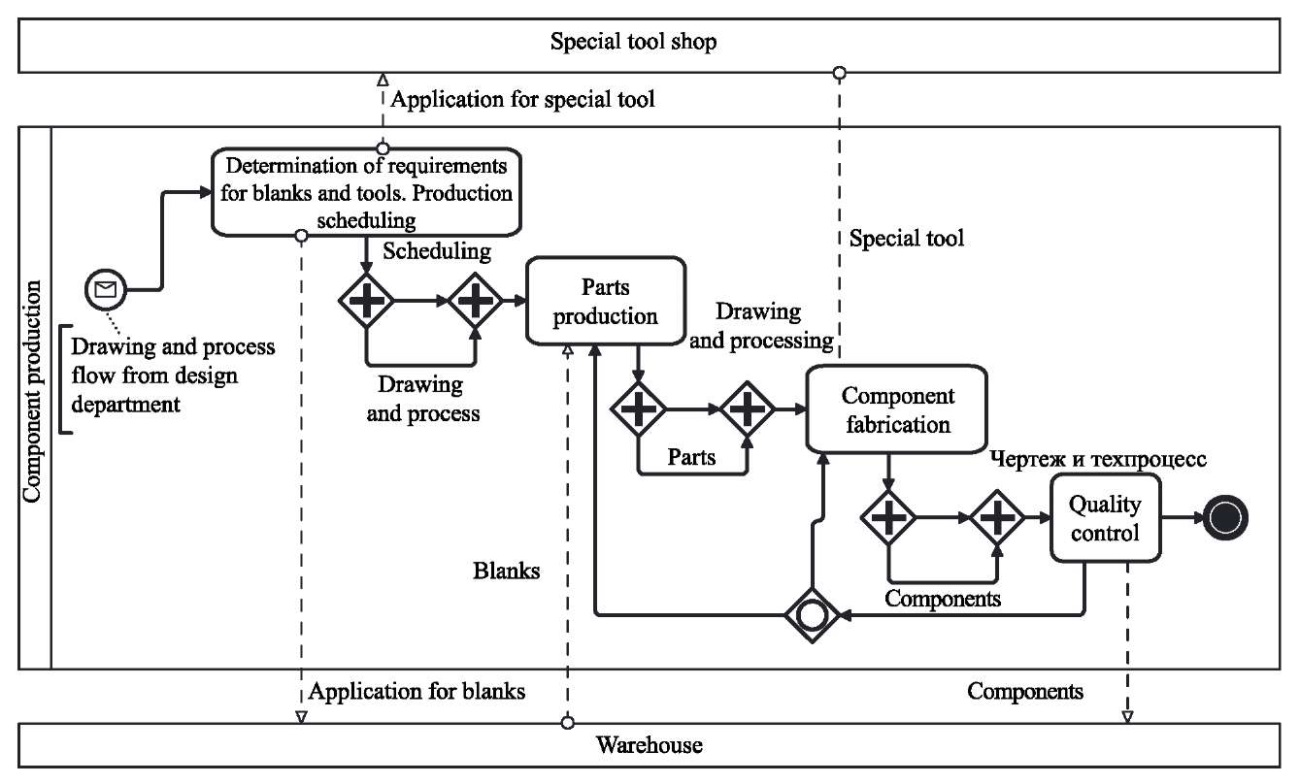
Fig. 3. BPMN diagram corresponding to NFO diagrams
Figure 3 shows clearly the problem of visibility and comprehensibility of the BPMN diagram. The reason is the requirement of the IDEF3 standard integrated into BPMN for the presence of only one input and one output. The fact is that each organizational-business and engineering-manufacturing process involves not only the transformation of the input product into an output one, but also document flow. Thus, any process must have at least two inputs and two outputs: product (material or informational) and documentary (informational). This is not taken into account by the programmers who created BPMN. In addition, Figure 3 allows us to state that event marker icons essentially do not add anything to the diagram content, since all connections are labeled. At the same time, graphic elements are more difficult to use. You need to remember both their meaning and the placement rules.
Converting BPMN diagram to NFO. The following four operations provide converting BPMN diagram to NFO. The correspondence between BPMN and NFO elements is presented in the Materials and Methods section. The logical operation sign “®” (implication) means replacing the object to the left of the sign with the object to the right of it.
1. BPMN pool with relationships is converted into context NFO diagram.
1.1. Pool ® context NFO element defined to the object level.
1.2. Pool start event and end event(s) ® functional relationships of the context NFO element corresponding to the NFO approach relationship classification.
1.3. If, in addition to the pool, there are tracks associated with it, then the pool relationships with tracks ® functional relationships of the context NFO element corresponding to the classification.
1.4. Tracks external to the pool ® NFO elements (defined to the object level) as external entities in relation to the context NFO element.
1.5. If there are BPMN elements on the external tracks, then these tracks ® NFO elements with subsequent decomposition.
2. BPMN pool tracks are transformed into a decomposition diagram of context NFO element corresponding to BPMN pool .
2.1. Pool track ® decomposition elements of context NFO element corresponding to BPMN pool.
2.2. Each BPMN track ® NFO element defined to the object level.
2.3. Start event(s) and end event(s) of a track, as well as relationships to other tracks (if any) ® functional relationships of NFO element corresponding to a track from the NFO approach relationship classification.
3. Subprocesses on BPMN track are transformed into NFO element decomposition diagram corresponding to the BPMN track.
3.1. Subprocesses on BPMN track ® elements of decomposition of NFO element corresponding to BPMN track.
3.2. Each BPMN subprocess ® NFO element defined to the function level.
3.3. Subprocess relationships ® relationships from the NFO approach relationship classification taking into account BPMN event triggers.
3.4. BPMN track gateways ® NFO elements with certain logical functions.
3.5. Gateway relationships ® relationships from the NFO approach relationship classification taking into account BPMN event triggers.
4. The tasks of BPMN subprocess are transformed into a decomposition diagram of the NFO element corresponding to the BPMN subprocess .
4.1. BPMN subprocess tasks ® decomposition elements of the NFO element corresponding to the BPMN subprocess.
4.2. Each BPMN task ® NFO element defined to the function level.
4.3. Task relationships ® relationships from the NFO approach relationship classification taking into account BPMN event triggers.
4.4. BPMN subprocess gateways ® NFO elements with defined logical functions.
Figures 4–9 show an example of converting BPMN diagram into NFO using the above procedure. Here, the BPMN diagram (Fig. 4) was also created using the Stormbpmn program in accordance with the BPMN rules. To build the NFO diagram (Fig. 5–9), the CASE tool NFO-toolkit was used.
The scheme of production of plastic components from the requirement for development of the process to the issuance of products is shown. In this case, the following are taken into account:
– development, analysis and fine-tuning of the process for manufacturing a part on an injection molding machine;
– parameters for setting up the injection molding machine;
– obtaining plastic;
– loading the machine;
– heating the plastic to a specified temperature;
– forming and releasing products.
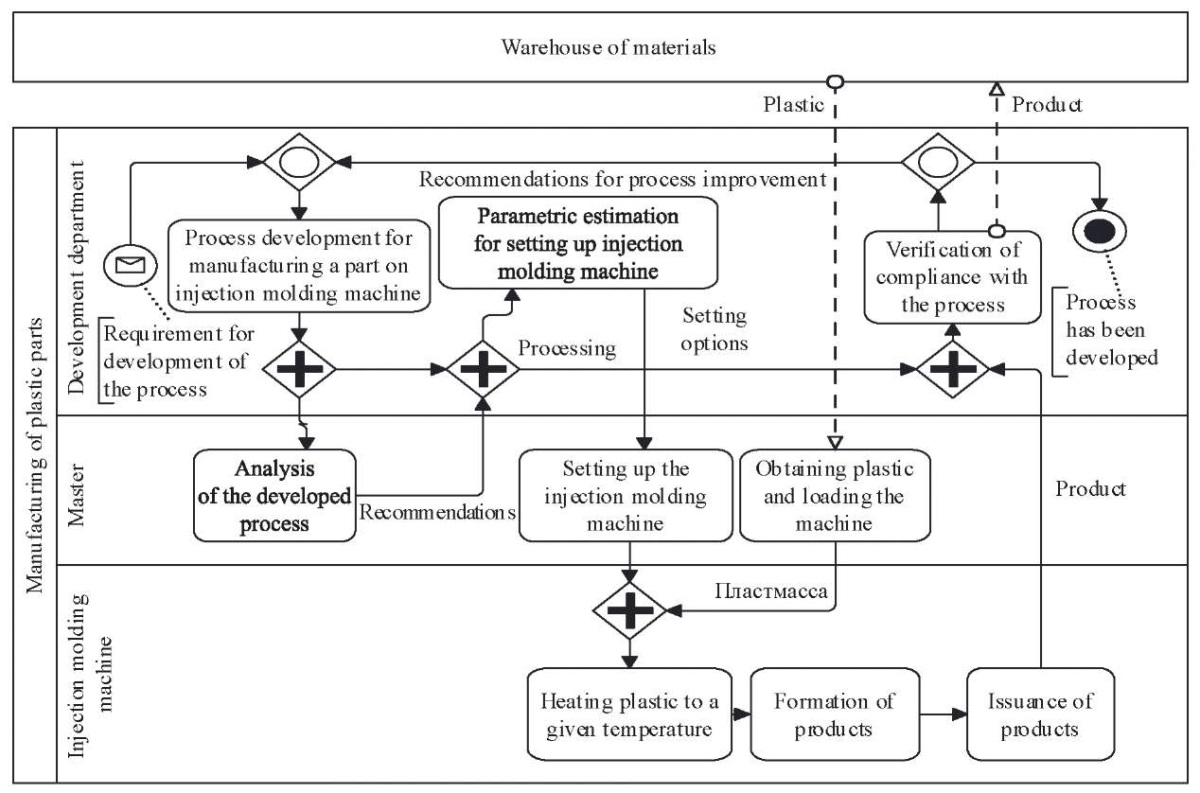
Fig. 4. BPMN diagram

Fig. 5. Context NFO diagram with functional relationships of BPMN diagram
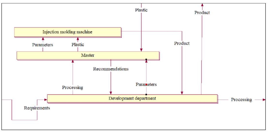
Fig. 6. Decomposition of context NFO diagram corresponding to the tracks of BPMN diagram pool
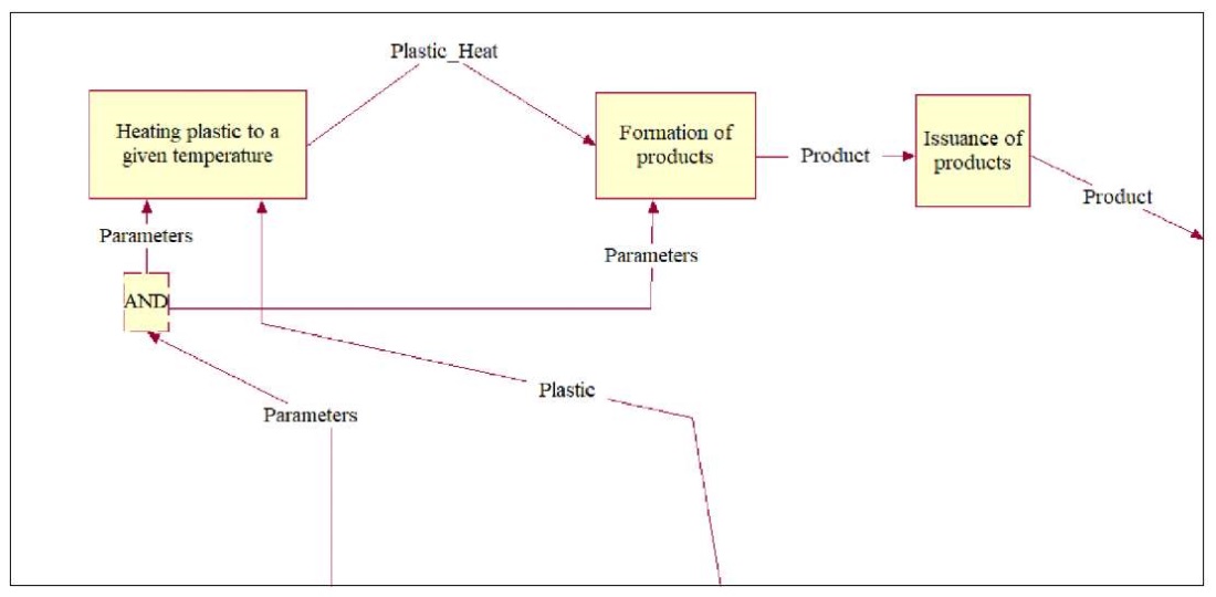
Fig. 7. Decomposition of NFO element “Injection Molding Machine”, corresponding to decomposition of the track of the pool “Injection Molding Machine” of BPMN diagram

Fig. 8. Decomposition of NFO element “Master”, corresponding to the decomposition of the pool track “Master” of BPMN diagram
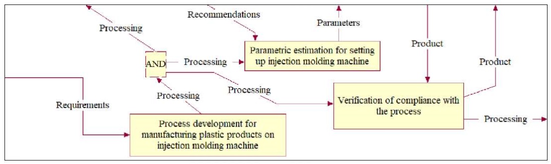
Fig. 9. Decomposition of NFO element “Development Department”, corresponding to decomposition of pool track “Development Department” of BPMN diagram
Analysis of Figures 4–9 allows us to state that the transformation of BPMN diagram into a diagram in NFO notation makes the description of the process more understandable, since it provides seeing it not only as a whole (in context), but also to any degree of detail. In this case, fewer icons are used, and this is a more convenient option, since it does not require remembering the meaning of graphic elements and the rules for their placement.
Description of NFO diagrams in XPDL language. In the Introduction section, the advantage of BPMN over other notations is noted: the means of translating BPMN diagrams into business process execution languages (e.g., XPDEL8) allow for the automation of organizational-business and engineering-manufacturing processes. However, this feature is easily transferred to the NFO notation. The main elements of the method for describing NFO diagrams in the XPDL language are presented in Table 1 by analogy with paper [15].
Table 1
Description of NFO Diagrams in XPDL Language
|
NFO diagram element |
XPDL Construction |
|
Process (context) |
<Activity id=«Имя»> <BlockActivity /> … </Activity> |
|
Process (on decomposition) |
<Activity id=«Имя»> <Implementation> <SubFlow /> … </Implementation> </Activity> |
|
Connector “AND” |
<Activity> <Route/> <TransitionRestriction> <Join Type=«AND»/> </TransitionRestriction> </Activities> |
|
Splitter “AND” |
<Activity> <Route/> <TransitionRestriction> <Split Type=«AND»/> </TransitionRestriction> </Activities> |
|
Connector “OR” |
<Activity> <Route/> <TransitionRestriction> <Join Type=«OR»/> </TransitionRestriction> </Activities> |
|
Splitter “OR” |
<Activity> <Route/> <TransitionRestriction> <Split Type=«AND»/> </TransitionRestriction> </Activities> |
|
Connector “Exclusive OR” |
<Activity> <Route/> <TransitionRestriction> <Join Type=«XOR»/> </TransitionRestriction> </Activities> |
|
Splitter “Exclusive OR” |
<Activity> <Route/> <TransitionRestriction> <Split Type=«XOR»/> </TransitionRestriction> </Activities> |
|
Functional relationship without a source (input) or without a consumer (output)) |
<Transition/> id=«Имя» /> |
|
Supportive connection between subprocesses |
<Transition id=«L» from=«Имя!» to=«Имя?» /> |
|
External entities |
<Activity> <Route type=«in» /> </Activity> или <Activity> <Route type=«out» /> </Activity> |
|
Process executor |
<Participant type=«_____»/> 1. Role 2. OrganisationUnit 3. Human 4. System 5. Resource 6. RecourceSet |
|
Interaction of two processes using two relashionships |
<Activities> <Activity id=«Имя!»> <Implementation> <SubFlow /> <TransitionRamification> <Split Type=«AND» /> <Transition id=«M» from=«Имя!» to=«Имя?» /> <Transition id=«I» from=«Имя!» to=«Имя?» /> </TransitionRamification> </Implementation> </Activity> <Activity id=«Имя?»> <Implementation> <SubFlow /> <TransitionMerger > < Join Type =«AND» /> <Transition id=«M» from=«Имя!» to=«Имя?» /> <Transition id=«I» from=«Имя!» to=«Имя?» /> </TransitionMerger> </Implementation> </Activity> </Activities> |
The table shows that when converting BPMN diagrams to NFO, it is possible to translate them into the process execution language.
Discussion. Thus, in BPM systems, not only BPMN notation can be used to build process models for the purpose of their automation, but also NFO notation, which provides a simpler procedure for creating models and their greater visibility.
The adequacy and practical value of this approach can be judged by the following data compiled by the authors:
– BPMN diagram;
– context NFO diagram with functional relationships of the BPMN diagram;
– decomposition of the context NFO diagram corresponding to the tracks of the BPMN diagram pool;
– decomposition of the NFO element “Injection molding machine” corresponding to the decomposition of the track of the “Injection molding machine” pool of the BPMN diagram;
– decomposition of the NFO element “Master” corresponding to the decomposition of the track.
The illustrative material proves the advantages of NFO notation. The transformation from BPMN diagram to NFO has revealed two advantages of this approach. First: the description in NFO notation opens up the possibility of analyzing the process as a whole (i.e., in context) and with any level of refinement (decomposition). Second: NFO notation uses fewer specific icons. This is a more convenient option, because:
– time required to remember the meaning of graphic elements and the rules for their placement is cut;
– risk of incorrect use of graphic elements in diagrams is reduced.
All this is clearly visible in Figures 4–9. In addition, to show the acquisition and dispatch of material resources to an external entity within BPMN, it is required to use a dotted arrow intended to indicate a message flow, not a material flow. This creates problems both at the stage of constructing the model by the analyst and at the stage of reading it by the designer or manager. Diagrams in NFO notation do not have this drawback.
Next. The NFO diagram shows better from which resources the desired result is obtained. This is explained by the fact that the NFO approach is initially focused on accounting for both material and information flows (connections). Hence another advantage. It is possible to conduct a functional cost analysis using a CASE tool that provides construction of NFO diagram. This is impossible for a diagram in BPMN notation, since this principle does not have a standard interpretation of connections as flow elements.
Discussing the data in Table 1, it is appropriate to note the prospects for Russification of the material. Here, the XPDL language constructs are naturally presented in English. However, it is planned to automate the execution of the models created by the authors of the article. And in the new solutions, the process names will be in Russian. As we can see, in this case, the attribute “Name” is written in Cyrillic.
Conclusion. Research of the normative systems of notation of the system-object approach “node – function – object” (NFO) and BPMN show that NFO notation is more universal and provides eliminating a number of shortcomings of BPMN diagrams through reproducing them by NFO notation. The results of the presented work will contribute to the development of the theory and practice of graph-analytic modeling of processes.
As a result of the conducted research, procedures for mutual transformation of BPMN and NFO diagrams were created. In addition, a description of the elements of the NFO approach notation in the XPDL business process execution language is shown, which equalizes the applied capabilities of the NFO notation with BPMN. In the future, XPDL structures will be Russified. It is assumed that the models created by the authors of this article will be executed by software methods, and the process names will be in Russian.
In general, the application of the results obtained will simplify the procedure for constructing graphical models of processes and their automation.
1. BPM Systems Market 2024: Analytical Review. URL: https://iaassaaspaas.ru/rating/bpm-sistemy (accessed: 12.06.2025).
2. Top-8 Methods of Business Process Analysis for 2025. (In Russ.) URL: https://listohod.ru/blog/top-8-metodov-analiza-biznes-processov (accessed: 12.06.2025).
3. BPMN Notation: Pros, Cons, and Scope. (In Russ.) URL: https://www.directum.ru/blog-post/notacija_bpmn__pljusy_minusy_i_oblast_primenenija (accessed: 12.06.2025).
4. Typical Mistakes in Modeling Business Processes in BPMN Notation. (In Russ.) URL: https://www.artofba.com/post/common_mistakes_bpmn_diagrams_part1_ru (accessed: 12.06.2025).
5. Top 25 Errors in BPMN. (In Russ.) URL: https://bpmn2.ru/blog/top-25-oshibok-bpmn (accessed: 12.06.2025).
6. Why You Should Abandon BPMN. (In Russ.) URL: https://habr.com/ru/articles/681262 / (accessed: 12.06.2025).
7. XPDL Support and Resources. URL: https://wfmc.org/xpdl/ (accessed: 08.06.2025).
8. XPDL Support and Resources. URL: https://wfmc.org/xpdl/ (дата обращения: 08.06.2025).
1. Panteleev AS, Shmatin AK. Problems of Digitalization and Robotization in Modern Russian Realities. Avtomatizirovannoe Proektirovanie v Mashinostroenii. 2022;(13):155–158. (In Russ.) https://doi.org/10.26160/2309-8864-2022-13-155-158
2. Bochkaryov PYu, Korolev RD, Bokova LG. Comprehensive Assessment of the Manufacturability of Products. Advanced Engineering Research (Rostov-on-Don). 2023;23(2):155–168. https://doi.org/10.23947/2687-1653-2023-23-2-155-168
3. Korotkii AA, Yakovleva DA, Maslennikov AA, Golovko IV. Modeling of Information Support to Optimize Logistics Tasks in Transport Sector Using a Programmable Container Transformer Simulator. Advanced Engineering Research (Rostov-on-Don). 2020;20(3):311–316. https://doi.org/10.23947/2687-1653-2020-20-3-311-316
4. Alenikov AS, Mamonova IV, Kololeeva KI. Variant Approaches to the Choice of Notation When Modeling Business Processes in the Enterprise. Bulletin of the Academy of Knowledge. 2020;39(4):33–41.
5. Aksenova OP, Aksenov KA, Antonova AS, Smoliy EF. The Analysis of Graphic Notations for Simulation Modeling of Enterprise Business Processes. Scientific Review. Technical Science. 2014;(1):45–54. URL: https://scienceengineering.ru/ru/article/view?id=17 (accessed: 17.06.2025).
6. Udaltsova NL. Modern Methods of Business Process Analysis and Modeling. Leadership and Management. 2021;8(2):185–200. https://doi.org/10.18334/lim.8.2.112126
7. Vakorin MP, Konstantinov DS, Mylnikova AP. Assessment of the Applicability of Business Process Description Notation for Modeling the Information Security Risk Management Process in an Organization. Young Scientist. 2022;445(50):6–8. (In Russ.) URL: https://moluch.ru/archive/445/97853/ (accessed: 15.06.2025).
8. Repin V. Modeling Business Processes in BPMN Notation in Business Studio 5: Field Guide. Moscow: Izdatel'skie resheniya; 2020. 106 p. (In Russ.)
9. Potryasaev SA. Integrated Modeling of Complex Processes Based on BPMN Notation. Journal of Instrument Engineering. 2016;59(11):913–920. https://doi.org/10.17586/0021-3454-2016-59-11-913-920
10. Zhikharev AG, Zimovets OA, Tuboltsev MF, Kondratenko AA. Systems Theory and Systems Analysis. SI. Matorin (ed). Moscow: Direktmedia Pablishing; 2021. 456 p. (In Russ). URL: https://biblioclub.ru/index.php?page=book&id=574641 (accessed: 05.06.2025).
11. Belaychuk AA, Bratchenko SA. Essential and Redundant Gateways in BPMN 2.0. Business Strategies. 2017;(4):3–7. https://doi.org/10.17747/2311-7184-2017-4-03-07
12. Ivanov S, Kalenkova A. Comparing Process Models in the BPMN 2.0 XML Format. Proceedings of ISP RAS. 2015;27(3):255–266. https://doi.org/10.15514/ISPRAS-2015-27(3)-17
13. Matveev AS, Rudenko AYu, Prochukhan VV. Development of Recommendations for Transition from IDEF0 Notation of Business Processes Modeling to BPMN Notation. Business. Education. Law. Bulletin of Volgograd Business Institute. 2016;36(3):176–182. URL: https://vestnik.volbi.ru/upload/numbers/336/article-336-1688.pdf (accessed: 17.06.2025).
14. Zimovets OA, Malkush EV, Matorin SI, Korsunov NI. Comparison of DFD, IDEF0, IDEF3, EPC and BPMN Notations with UFO-analysis Notation. Economics. Information Technologies. 2024;51(4):936–945. https://doi.org/10.52575/2687-0932-2024-51-4-936-945
15. Klimenko AV, Zhulin AB, Plaksin SM, Golovshchinsky KI, Sivasheva NM, Suvorova IK, et al. Development of Methodological Recommendations for the Description and Optimization of Processes in Executive Authorities in the Context of Preparation for the Implementation of the EAR: Research Report. Moscow: Higher School of Economics; 2010. 193 p. (In Russ). URL: https://textarchive.ru/c-1946975.html (accessed: 08.06.2025).
Alexander G. Zhikharev, Dr.Sci. (Eng.), Associate Professor, Director of the Institute of Engineering and Digital Technologies
85, Pobedy Str., Belgorod, 308015
Scopus ID: 56736375800
Elena V. Malkush, Postgraduate student of the Department of Information and Robotic Systems
85, Pobedy Str., Belgorod, 308015
Sergey I. Matorin, Dr.Sci. (Eng.), Professor of the Department of Information and Robotic Systems
85, Pobedy St, Belgorod, 308015
Scopus ID: 6602150407
ResearcherID: AAN-5244-2021
A universal method for converting diagrams between NFO and BPMN notations to improve clarity is presented. Six operations for converting NFO to BPMN and four operations for the reverse transformation are developed. It is shown that NFO notation reduces the number of graphic icons and simplifies diagram reading.
NFO elements are described in XPDL, a process execution language, for subsequent automation. The method provides the consideration of material and information flows and the functional-cost analysis. The results are applicable to the design, automation, and optimization of production processes.
Zhikharev A.G., Malkush E.V., Matorin S.I. Improving Business Process Model and Notation Diagrams with the Node-Function-Object Approach. Advanced Engineering Research (Rostov-on-Don). 2025;25(3):256-268. https://doi.org/10.23947/2687-1653-2025-25-3-256-268. EDN: PWKCXM


Advanced Engineering Research (Rostov-on-Don)
ISSN 2687-1653 (Online)
Contact with: Publisher / Editorial Office of the Journal
Publisher: Don State Technical University - DSTU, Rostov-on-Don, Russia - https://donstu.ru/en/
Editor-in-Chief: Alexey N. Beskopylny, Dr.Sci. (Eng.), Professor, Vice-Rector, Don State Technical University (Rostov-on-Don, Russia)
Don State Technical University
1, Gagarin Sq., Rostov-on-Don, 344003, Russia
tel.: +7 (863) 2738-372, e-mail: vestnik@donstu.ru
16+
Processing of personal data


