


Contents
Scroll to:
https://doi.org/10.23947/2687-1653-2023-23-3-231-240
Scroll to:
Introduction. When milling complex-profile surfaces of parts, the selection of tool trajectories and orientations affect the roughness parameters. However, in the studies devoted to the formation of trajectories, recommendations to provide the quality of microgeometry of surfaces were not taken into account. Moreover, when writing programs for CNC equipment in CAM systems, the limitations of cutting modes were determined exclusively using a geometric approach. It did not take into account the influence of the orientation angles of the sphero-cylindrical tool relative to the normal plane on the quality of surface treatment, namely on roughness. The work was aimed at the creation of the methodology for selecting the limiting values of the orientation angles of a sphero-cylindrical tool to optimize the process of machining spatially complex surfaces. The tasks included achieving the minimum values of the amplitude roughness parameter Rz and determining the effectiveness of various machining paths.
Materials and Methods. Methods of correlation and regression analysis were used, the results were compared and generalized. The least-squares method was applied to estimate the parameters of the regression equation. The DMU 50 ecoline processing center was used for the experimental studies. Roughness was measured on a Surfcam 1800 D profilometer. The material of the samples was steel 12X18N10T. The material of the tool was hard alloy 1620 Sandvik with PVD coating (physical vapor deposition, the closest domestic analogue is T15K6).
Results. It has been shown in detail how roughness parameters Rz depend on the angle of inclination and the diameter of the tool. Twenty examples were summarized in a table. Natural regression coefficients were calculated using linear and hyperbolic models. It was found that the diameter of the tool had a greater effect on the formation of roughness parameter Rz than the angle of inclination. For a detailed description of the influence features, the coefficients of multiple, partial, paired correlation and multiple determination were compared. The limitations associated with the angles of inclination of the tool when processing complex surfaces were determined. A scheme for calculating the angle of the normal was visualized, which included the selected step along the axis to determine the lengths of the segments of the broken curve. The profilograms of surfaces obtained with different shaping trajectories were given in the form of drawings. This allowed us to conclude that milling from top to bottom is unsuitable when the tool is tilted 5°– 35°. A map has been compiled by which it is possible to judge the roughness, knowing the type of milling and the inclination angle (from 5° to 80 °). The dependence of the roughness parameter on the processing speed and the use of coolant was represented graphically. The calculated parameters for determining the optimal angle of inclination of the tool were tabulated. Their analysis proved the adequacy of the proposed method of preparing control information.
Discussion and Conclusion. The presented technique made it possible to determine the optimal values of the orientation angles of the sphero-cylindrical tool, taking into account the cutting speed and the minimum possible amplitude roughness parameter Rz. The pattern of feeding fz = 0.4 mm/tooth for surface areas with a total angle of 5°– 50°was considered. In this case, processing along trajectories in the passing, opposite and bottom-top directions, provided roughness in the range of 3–6 µm according to parameter Rz. The top-down toolpath is not recommended for use in final operations due to the significant height of parameter Rz.
Gimadeev M.R., Nikitenko A.V., Berkun V.O. Influence of the Sphero-Cylindrical Tool Orientation Angles on Roughness under Processing Complex-Profile Surfaces. Advanced Engineering Research (Rostov-on-Don). 2023;23(3):231-240. https://doi.org/10.23947/2687-1653-2023-23-3-231-240
Introduction. The reliability of machine parts is determined by such performance properties (PP) of surfaces as wear resistance, tightness, strength, quality of coatings [1]. These PP depend on the physico-mechanical and geometric parameters of functional surfaces, including roughness [2–4].
The analysis of the scientific literature suggests a growing interest in the topic of providing the necessary roughness parameters due to the reasonable selection of trajectories of shaping movements and orientation of the sphero-cylindrical tool when milling spatially complex surfaces (SCS) [5–7]. Examples of such parts are forming elements of die tooling, master models for casting, executive surfaces of gearing [8–10].
A number of authors studied the influence of strategies under the milling of SCS and methods of optimizing machining [10–12]. However, knowledge about the formation of trajectories does not take into account the recommendations for providing the quality of microgeometry of the surfaces of the part. It should also be noted that when creating programs for CNC equipment in CAM systems, the limitations of cutting modes are determined exclusively using a geometric approach [13][14]. It does not take into account the influence of the orientation angles of the sphero-cylindrical tool relative to the normal plane on the quality of surface treatment, namely on roughness. The method of selecting the angles of tool orientation based on empirical models can overcome these disadvantages. Its advantages:
The study was aimed at the creation of a methodology for selecting the limiting values of the orientation angles of a sphero-cylindrical tool to optimize the process of machining spatially complex surfaces. The tasks included achieving the minimum values of the amplitude roughness parameter Rz and determining the effectiveness of various machining trajectories.
Materials and Methods. Thus, CAM systems provide forming multi-coordinate machining trajectories with tracking of additional parameters, such as collisions, the point of contact between the tool and the part, etc. The sphero-cylindrical tool touches the part at point Pi (xi. yi. zi) = Pd (xd. yd. zd). At the same time, it is required to avoid machining with the center of the cutter and orient the tool with an angle of inclination of at least 5°–15°.
In the final operations, the effective cutting speed is determined by the effective diameter. At an equal rotational speed, it grows with the increase in the angle of inclination of the tool to the workpiece. An increase in the cutting speed generally causes a decrease in the microhardness of the surface, and with an increase in V > 75 m/min, the microhardness parameters change slightly [12]. The dissipation rate strongly depends on the cutting speed and the volume of the material being removed; therefore, cutting-tool lubricant (CTL) is needed to intensify the cutting
process [15].
For the experiments, technological equipment with CNC was used, a five-axis machining center DMU 50 ecoline with a maximum spindle frequency of 8,000 rpm. The surface roughness was measured by a Surfcom 1800 D profilometer. Sandvik end mills of the R216 series were used for processing 12X18H10T steel. The material was hard alloy 1620 with PVD coating (the closest domestic analogue is T15K6). The diameter was 8 mm, the number of
teeth — 2. To provide a uniform allowance (ap = 0.2 mm), mechanical treatment with sphero-cylindrical cutters was carried out before the final milling operation.
Research Results. Before determining the angles of inclination, it was required to establish how variable factors affected the response function. In this case, we are talking about the surface roughness according to parameter Rz (µm). To find empirical mathematical models of milling with a sphero-cylindrical tool, we took the independent variables: X1 — diameter (D, mm) and X2 — the angle of the tool inclination (γ, °). The initial data for the analysis were considered in previous studies (when applied to tooth fz = 0.4 mm/tooth) [16–19] (Table 1).
Table 1
Roughness parameters Rz depending on the angle of inclination
and diameter of the tool
|
Angle, ° |
Tool diameter, mm |
|||
|
6 |
8 |
10 |
12 |
|
|
10 |
9.33 |
7.66 |
5.99 |
4.33 |
|
20 |
8.59 |
7.06 |
5.53 |
4.01 |
|
30 |
7.85 |
6.46 |
5.07 |
3.69 |
|
40 |
7.11 |
5.86 |
4.61 |
3.37 |
|
50 |
6.37 |
5.26 |
4.15 |
3.05 |
Based on theoretical data on significant factors affecting roughness, linear (1.1) and hyperbolic (1.2) models were adopted:
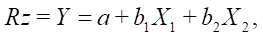 (1.1)
(1.1)
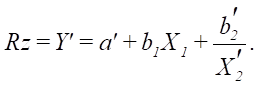 (1.2)
(1.2)
Here are the calculated natural regression coefficients:

The parameters of the two-factor regression equation were estimated using the standard least squares method; therefore, for simplicity of presentation, we omitted the formulas indicating the coefficients. Standardized
β-coefficients:

Comparison of the modules of the values of standardized regression coefficients β allowed us to conclude that factor X1 (tool diameter) had more effect on the formation of the roughness parameter Rz than X2 (inclination angle). Coefficients of multiple, partial, paired correlation and multiple determination:
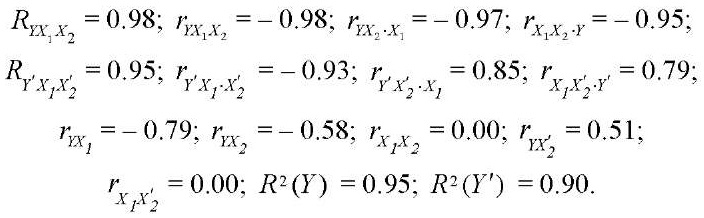
Comparing the coefficients, we drew the following conclusions.
When factor X2 was fixed at a constant level, factor X1 most strongly affected (|0.98| > |0.79|). When comparing the coefficients of the hyperbolic model, (|0.93| > |0.79|).
When factor X1 was fixed, the effect of factor X2 on Rz increased for both models: linear |0.97| > |0.58|, hyperbolic |0.93| > |0.51|.
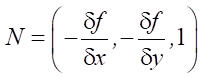
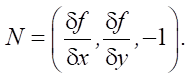
To ensure the uniformity of the microrelief of the surface, the dependence of the feed and the effective diameter of the tool (Dcap) was established, which varied depending on the angle of processing. We defined the limitations associated with the angles of the tool inclination when processing the SCS. To do this, the surface of the part was to be divided into sections and the normal angles calculated. If z = f (x. y), then, in general, the orientation of the tool to the surface was set by selecting the direction of the normal.
At cos γ = 1 / |N|:
 . (2.1)
At cos γ = –1 / |N|:
 (2.2)
(2.2)
To determine the inclination angle of the tangent plane, the following equation was used:
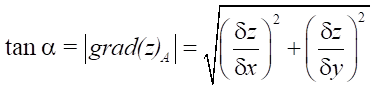 , (3)
, (3)
where α = |90° – γ|.
AV Nikitenko [20] presented a model for optimizing the orientation angle of a part with corrective angles of inclination А and B relative to X and Y axes:
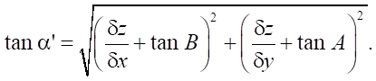 (4)
(4)
For a special case (Fig. 1), determination of angle λ to normal N:
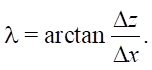 (5)
(5)
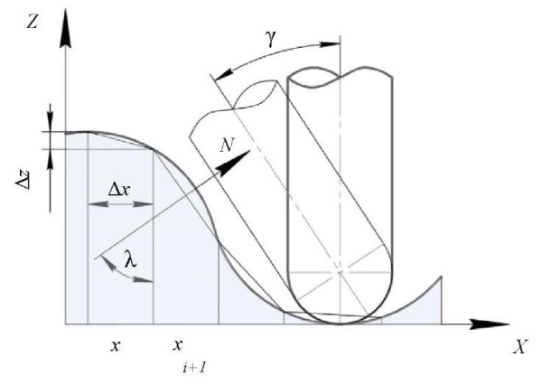
Fig. 1. Scheme for calculating the angle of the normal:
N — normal; λ — angle to the normal;
Δx — selected step along X axis to calculate the lengths
of the polyline curve segments, mm;
Δz — distance along Z axis, depending on the step along X axis, mm
With a discretely defined surface profile, the length of the curve describing the profile geometry:
 (6)
(6)
Here, the length of the polyline section 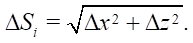
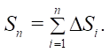
The roughness of Rz was considered as an output parameter (Fig. 2), taking into account the limitations associated with the trajectories of motion and the angles of inclination of the sphero-cylindrical tool.
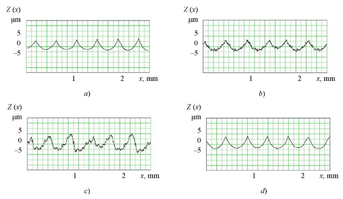
Fig. 2. Profilograms of surfaces obtained with different shaping trajectories
at Γ = 35°–45°:
a — passing milling;
b — counter milling;
c — top-bottom milling;
d — bottom-up milling
Top-bottom milling is characterized by the greatest amplitude, the unevenness of the resulting surface profile, and is not recommended for shaping with a tool tilted at an angle of 5°–35°.
The roughness selection map (Fig. 3) for Rz parameter is based on the results of the given and previous studies [16–19].
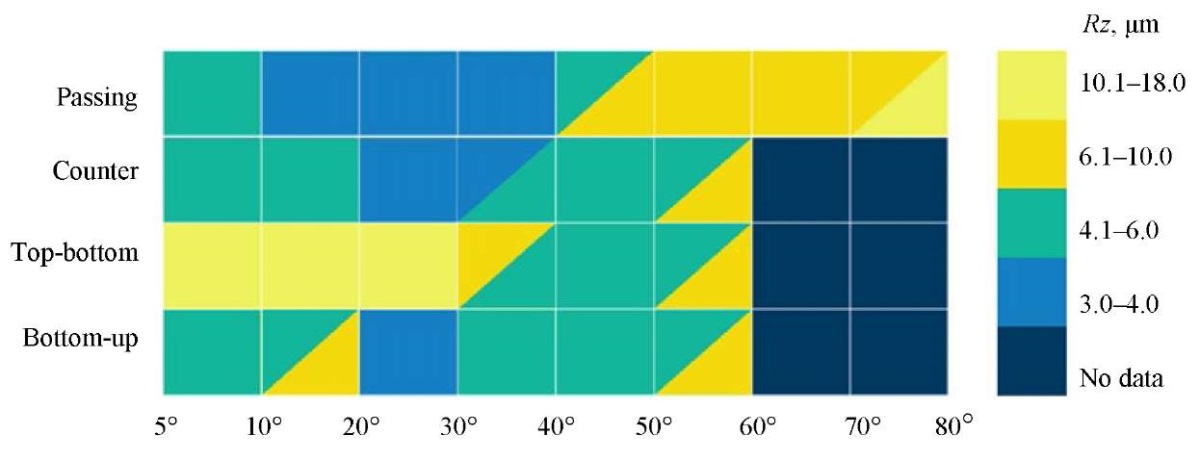
Fig. 3. Roughness selection map
When using CTL, a film was formed on the contact surfaces of the tool and the workpiece material, which helped to reduce adhesive wear. At the cutting speed V > 70 m/min, the effect of dynamic friction was reduced. At the same time, the duration of the physico-chemical effect of the medium on the contact surfaces went down, which limited the effect of the use of the CTL (Fig. 4).
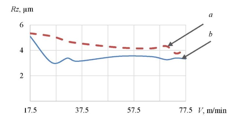
Fig. 4. Dependence of roughness parameter Rz on the machining speed:
a — without CTL;
b — with the use of CTL
The considered technique was aimed not at establishing critical values of possible orientation angles of a sphero-cylindrical tool for a specific object, but at achieving roughness parameters taking into account the effective cutting speed, feed, and inclination angles for a wide range of parts with concave-convex and linear sections. This approach could provide generalizing and clarifying the ways of optimizing machining. In addition to roughness, the limitations of the minimum effective cutting speed, depending on the effective diameter of the tool, were analyzed. At the same time, the minimum recommended effective cutting speed was (Vcap) — 75 m/min.
According to the feed and lateral pitch, the angle of orientation of the tool can correspond to positive and negative values. When calculating, it was considered modulo. Based on the calculated data (Table 2), the surface profile (Fig. 1) was divided into sections. The normal angles were determined, and the trajectories of the shaping movements were assigned to provide the required roughness, taking into account the angles of inclination of the tool.
Table 2
Design parameters for determining the optimal angle of inclination of the tool
|
n |
Δz, mm |
Δx, mm |
λ,° |
Γ = λ + γ,° |
Vсap at γ = 5 м/мин |
||
|
γ = 1 |
γ = 3 |
γ = 5 |
|||||
|
1 |
0.16 |
0.25 |
3.59 |
4.59 |
6.59 |
8.59 |
68.0 |
|
2 |
0.48 |
10.83 |
11.83 |
13.83 |
15.83 |
84.4 |
|
|
3 |
0.82 |
18.25 |
19.25 |
21.25 |
23.25 |
99.8 |
|
|
4 |
1.22 |
26.01 |
27.01 |
29.01 |
31.01 |
114.2 |
|
|
5 |
1.71 |
34.34 |
35.34 |
37.34 |
39.34 |
127.2 |
|
|
6 |
2.38 |
43.64 |
44.64 |
46.64 |
48.64 |
138.6 |
|
|
7 |
3.55 |
54.82 |
55.82 |
57.82 |
59.82 |
147.5 |
|
|
8 |
6.59 |
69.21 |
70.21 |
72.21 |
74.21 |
150.7 |
|
|
9 |
4.56 |
61.26 |
62.26 |
64.26 |
66.26 |
150.1 |
|
|
10 |
2.81 |
48.39 |
49.39 |
51.39 |
53.39 |
143.1 |
|
|
11 |
1.98 |
38.41 |
39.41 |
41.41 |
43.41 |
132.7 |
|
|
12 |
1.43 |
29.71 |
30.71 |
32.71 |
34.71 |
120.3 |
|
|
13 |
1.00 |
21.73 |
22.73 |
24.73 |
26.73 |
106.5 |
|
|
14 |
0.63 |
14.17 |
15.17 |
17.17 |
19.17 |
91.5 |
|
|
15 |
0.30 |
6.87 |
7.87 |
9.87 |
11.87 |
75.5 |
|
|
16 |
0.01 |
0.32 |
1.32 |
3.32 |
5.32 |
60.2 |
|
|
17 |
0.33 |
7.52 |
8.52 |
10.52 |
12.52 |
77.0 |
|
|
… |
… |
… |
… |
… |
… |
… |
|
|
ni |
1.03 |
22.43 |
23.43 |
25.43 |
27.43 |
107.8 |
|
|
ni+1 |
1.47 |
30.46 |
31.46 |
33.46 |
35.46 |
121.5 |
|
The measured roughness values, taking into account the recommended angles of inclination of the sphero-cylindrical tool and the movement trajectory, are minimal with respect to Rz parameter (from 3 to 6 µm). At the same time, these values correlate with data from other studies (Fig. 3). This allows us to conclude that the proposed method of preparing control information is adequate.
Discussion and Conclusion. The presented technique of selecting the limit values of the orientation angles of a sphero-cylindrical tool can be used to process the SCS with one tool without replacement, taking into account the accepted restrictions. The proposed approach makes it possible to determine the optimal values of the orientation angles of a sphero-cylindrical tool, allowing for the cutting speed and achieving the minimum possible amplitude parameter of roughness Rz.
We considered the situation for surface areas with a total angle of 5°–50° at feed fz = 0.4 mm/tooth. In this case, machining along trajectories in the passing direction, from bottom to top and in the opposite direction allowed for roughness in the range of 3–6 µm according to Rz parameter. This was less than the maximum values obtained by 15–30 %. At angles of 10°–40° and the passing processing direction, the minimum values of Rz — 3–4 µm were recorded. The trajectory of top-bottom movement was not recommended for use in final operations due to the significant height of the Rz profile. At the same time, the values of 4.1–6 µm for this trajectory were achieved in a narrow range of angles — 40°–50°.
1. Suslov AG, Federov VP, Nagorkin MN, Pyrikov IL. Complex Approach to Experimental Investigations of Metal Working Technological Systems to Ensure Parameters of Quality and Operation Properties of Machinery Surfaces. Science Intensive Technologies in Mechanical Engineering. 2018;(88(10)):3–13. https://doi.org/10.30987/article_5bb4b1f9abbc54.46761484
2. Ponomarev BB, Suong H Nguyen. Evaluation of Surface Roughness in Five-Axis Ball-End Milling. Proceedings of Higher Educational Institutions. Machine Building. 2020;(5(722)):21–31. https://doi.org/10.18698/0536-1044-2020-5-21-31
3. Pimenov D, Hassui A, Wojciechowski S, Mia M, Magri A, Suyama DI, et al. Effect of the Relative Position of the Face Milling Tool towards the Workpiece on Machined Surface Roughness and Milling Dynamics. Applied Sciences. 2019;9(5):842. https://doi.org/10.3390/app9050842
4. Averchenkov VI, Filippova LB, Pugach LI. Determination of Software Tool Compensation Values in the Preparation of Automated Production of the Use of Active Control Sensor Tool. Izvestiya Tula State University. 2013;(7−1):70–78. URL: https://tidings.tsu.tula.ru/tidings/pdf/web/file/tsu_izv_technical_sciences_2013_07_part_1.pdf (accessed: 05.04.2023).
5. Ižol P, Vrabel M, Maňková I. Comparison of Milling Strategies when Machining Freeform Surfaces. Materials Science Forum. 2016;862:18–25. https://doi.org/10.4028/www.scientific.net/MSF.862.18
6. Hassanpour H, Shajari S, Rasti A, Sadeghi MH. Investigation of Milling Strategies Effect on Microhardness of a Typical Curved Surface. Modares Mechanical Engineering. 2015;15(2):34–40. URL: https://www.researchgate.net/publication/270449928_Investigation_of_milling_strategies_effect_on_microhardness_of_a_typical_curved_surface (accessed: 05.04.2023).
7. Shajari S., Sadeghi M.H., Hassanpour H. The Influence of Tool Path Strategies on Cutting Force and Surface Texture during Ball End Milling of Low Curvature Convex Surfaces. The Scientific World Journal. 2014;2014:374526. https://doi.org/10.1155/2014/374526
8. Matras A, Kowalczyk R. Analysis of Machining Accuracy during Free form Surface Milling Simulation for Different Milling Strategies. Proceedings of the SPIE. 2014;9290:1–7. https://doi.org/10.1117/12.2075081
9. Ponomarev BB, Nguyen Sy Hien. The Influence of Tool Orientation on Cutting Forces during End Milling. Proceedings of Higher Educational Institutions. Machine Building. 2019;(3(708)):11–20. https://doi.org/10.18698/0536-1044-2019-3-11-20
10. Mali RA, Gupta TVK, Ramkumar J. A Comprehensive Review of Free-Form Surface Milling — Advances over a Decade. Journal of Manufacturing Processes. 2021;62:132–167. https://doi.org/10.1016/j.jmapro.2020.12.014
11. Xiurong Zhu, Yeu Wang. Process Analysis and Parameter Optimization of Five Axis NC Machine for Machining Complex Curved Surface Impellers. In: Proc. International Conference on Intelligent Transportation, Big Data & Smart City (ICITBS). New York: IEEE; 2019. P. 122−124. https://doi.org/10.1109/ICITBS.2019.00036
12. Zhidyaev AN, Masheryakov AV, Pronichev ND, Shulepov AP. Milling and Microballs Strengthening Conditions Influence on High-Temperature Alloys and Steels Parts’ Coating Surface Quality Experimental Investigation. VESTNIK of Samara University. Aerospace and Mechanical Engineering. 2012;(5–2(36)):245–251. URL: https://cyberleninka.ru/article/n/eksperimentalnoe-issledovanie-vliyaniya-rezhimov-frezerovaniya-i-uprochneniya-naparametry-kachestva-poverhnostnogo-sloya-detaley-iz/viewer (accessed: 05.04.2023).
13. Lapshin VP, Khristoforova VV, Nosachev SV. Relationship of Temperature and Cutting Force with Tool Wear and Vibration in Metal Turning. Obrabotka Metallov (Metal Working and Material Science). 2020;22(3):44–58. https://doi.org/10.17212/1994-6309-2020-22.3-44-58
14. Blau P, Busch K, Dix M, Hochmuth C, Stoll A, Wertheim R. Flushing Strategies for High Performance, Efficient and Environmentally Friendly Cutting. Procedia CIRP. 2015;26:361–366. https://doi.org/10.1016/j.procir.2014.07.058
15. Kuscheva ME, Klauch DN, Kobelev OA. Principles of Selection of Cutting Technological Mediums for Metal Cutting. Izvestiya MGTU “MAMI”. 2014;8(1-2):73–76. https://doi.org/10.17816/2074-0530-67737
16. Gimadeev MR, Li AA. Analysis of Systems for Automated Provision of Surface Roughness Parameters Based on Dynamic Monitoring. Advanced Engineering Research (Rostov-on-Don). 2022;22(2):116–129. https://doi.org/10.23947/2687-1653-2022-22-2-116-129
17. Davydov VM, Gimadeev MR, Nikitenko AV, Sarygin AV. Formation of Roughness Parameters Based on Correlation Relations during Finishing Milling of Spatially Complex Surfaces. Strengthening Technologies and Coatings. 2019;15(6(174)):243–249. URL: https://www.mashin.ru/files/2019/up619_web.pdf (accessed: 05.04.2023).
18. Gimadeev MR, Davydov VM. Correlation of the Roughness in Milling of Spherical Tool. Assembling in Mechanical Engineering and Instrument-Making. 2019;(5):219–224.
19. Gimadeev MR, Li AA, Berkun VO, Stelmakov VA. Experimental Study of the Dynamics of the Machining Process by Ball-End Mills. Obrabotka Metallov (Metal Working and Material Science). 2023;25(1):44–56. https://doi.org/10.17212/1994-6309-2023-25.1-44-56
20. Nikitenko AV. Development of a Model of Optimization of Angle of Orientation of a Workpiece when Processing Difficult Surfaces. Uchenye zametki TOGU. 2021;12(2):66–69. URL: https://pnu.edu.ru/media/ejournal/articles-2021/TGU_12_71.pdf (accessed: 05.04.2023).
Mihkail R. Gimadeev, Cand.Sci. (Eng.), Associate Professor of the Technological Informatics and Information Systems Department
136, Tihookeanskaya St., Khabarovsk, 680035
Aleksandr V. Nikitenko, Cand.Sci. (Eng.), Associate Professor of the Technological Informatics and Information Systems Department
136, Tihookeanskaya St., Khabarovsk, 680035
Vera O. Berkun, Design engineer, “PromMash” LLC: Postgraduate of the Technological Informatics and Information Systems Department, Pacific National University
l 1, 42 a, R. Matveevskoe, Khabarovsk, 680031
136, Tihookeanskaya St., Khabarovsk, 680035
Gimadeev M.R., Nikitenko A.V., Berkun V.O. Influence of the Sphero-Cylindrical Tool Orientation Angles on Roughness under Processing Complex-Profile Surfaces. Advanced Engineering Research (Rostov-on-Don). 2023;23(3):231-240. https://doi.org/10.23947/2687-1653-2023-23-3-231-240


Advanced Engineering Research (Rostov-on-Don)
ISSN 2687-1653 (Online)
Contact with: Publisher / Editorial Office of the Journal
Publisher: Don State Technical University - DSTU, Rostov-on-Don, Russia - https://donstu.ru/en/
Editor-in-Chief: Alexey N. Beskopylny, Dr.Sci. (Eng.), Professor, Vice-Rector, Don State Technical University (Rostov-on-Don, Russia)
Don State Technical University
1, Gagarin Sq., Rostov-on-Don, 344003, Russia
tel.: +7 (863) 2738-372, e-mail: vestnik@donstu.ru
16+
Processing of personal data


