


Contents
Scroll to:
https://doi.org/10.23947/2687-1653-2023-23-4-376-386
EDN: LFCYNM
Scroll to:
Introduction. As numerous production tests show, the use of manual arc welding (MAW) of thick-walled fittings of small diameter (up to 80 mm) does not provide a high-quality weld joint that meets the requirements of regulatory and technical documents of nuclear power plants (NPP). The solution to this problem is possible on the basis of research and development of welding technology with optimal heat input instead of MAW. Existing fusion welding technologies do not allow for optimal regulated heat input. However, this can be realized during the development and further use of the friction welding (FW) method. Therefore, this work aimed at developing a technology based on an automated technique of friction welding, which could provide the enhancing of the quality of weld joints of small diameter fittings of power equipment to the level of regulatory requirements.
Materials and Methods. Small diameter fittings with a conical contact surface made of low-alloy steel 10GN2MFA were used. The experimental study was performed on a friction welding machine MST–41. Methods of non-destructive and destructive quality control were used in accordance with the regulatory and technical documentation of nuclear power engineering.
Results. A methodology was developed, and the optimal dimensions of the conical contacting surface under welding were determined. It was shown that optimal heat input during friction welding was achieved by preparing a conical contacting surface in the angle range α = 30º–40º. The methodology and parameters of the friction welding mode for models of small diameter fittings were experimentally tested. In the course of the research, a cyclogram of the friction welding process was obtained and described, which confirmed the stage-by-stage formation of the weld joint due to the sequential inclusion of annular sections of the conical surface of the connected parts in the heating stage. The results of non-destructive and destructive testing were obtained, confirming the presence of a high-quality weld joint at the level of the requirements of the regulatory and technical documents of the NPP.
Discussion and Conclusion. The obtained research results can be used to develop the technology of friction welding of pipes, as well as products made of carbon and low-alloy steels.
Poletaev Yu.V., Shchepkin V.V. Advantages of Friction Welding of Fittings with Small Diameter Conical Contact Form. Advanced Engineering Research (Rostov-on-Don). 2023;23(4):376-386. https://doi.org/10.23947/2687-1653-2023-23-4-376-386. EDN: LFCYNM
Introduction. The key problem of welding small diameter fittings is short weld length, which does not allow for full control of the quality of the manual arc welding process. Supplying welding equipment to the welding site is also not always technologically possible.
Weld-in and weld-on fittings are connected to the basic part by a fillet seam through manual arc welding with a coated electrode. Weld-in fittings are welded from the outside or from the inside with a constructive faulty fusion. In any case, the presence of non-welded gaps in the joints, which are stress concentrators, reduces the operability of the structure, as it can cause cracks. A more perfect connection is one that has no unwelded gap. Sometimes, to obtain a guaranteed penetration of the entire wall of the fitting and to exclude the possibility of cracking from faulty fusion, a moulding back ring removable after welding is used, or a thick-walled pipe blank is soldered in. After welding, it is drilled out to the internal diameter specified in the drawing (Fig. 1). This is quite time-consuming, but justified in critical structures, e.g., in the manufacture of equipment for nuclear power plants [1]. This method is shown in Figure 1, where the fitting assembly is shown before (a) and after welding (b). Here: D — inner diameter of fitting; h, b — welded joint legs; S — fitting wall thickness. According to the normative document1, from which the drawing is borrowed, the permissible size for the wall thickness of the fitting should be ≥2 mm; bluntness of the welded joint — 4±1 mm; included angle — 50°±5°.
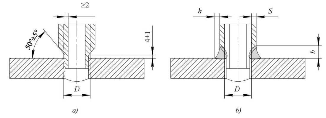
Fig. 1. Fitting unit:
a — before welding; b — after welding and removing the weld root
To weld the fitting, the following process operations are performed: turning the hole in the housing, grooving on the fitting, assembly of the unit maintaining perpendicularity, tacking the fitting, multilayer welding, removal of the weld root through boring the inner diameter to the standard dimensions.
The known disadvantages of the MAW do not allow for stable quality of the welded joint and are characterized by a large volume of cast weld metal in a limited space. This causes overheating and high residual stresses, which requires additional operations of heat treatment. The cost of repairing equipment in the event of a breakdown is high. This results in time and economic expenditures [2–6].
The analysis of the results of the literature review and production experience indicate the technical and economic feasibility of abandoning the use of the MAW method for obtaining welded thick-walled connections of fittings and pipes of small diameter (up to 80 mm) [7][8].
In this regard, it was decided to investigate the effect of the grooving shape and the method of friction welding instead of MAW to provide optimal minimum heat input and stable quality of welds. Friction welding is characterized by optimal heat input (compared to fusion welding methods), in which a fine-grain structure is formed with a low level of residual welding stresses and a high level of mechanical properties [9][10].
The objective of the work is to raise the quality of welds of small diameter fittings of power equipment to the level of regulatory requirements based on the development of an automated friction welding method.
Materials and Methods. Theoretical and experimental studies were carried out on welds made of low-alloy steel 10GN2MFA, used as the basic structural material for the manufacture of a steam generator, pressure compensator, and other critical NPP equipment2.
In the work, a computational and experimental method was used to select the optimal shape of the joined surfaces under welding.
The developed friction welding technology was implemented when performing welded joints of fittings on the MST-41 installation.
Methods and volumes of non-destructive (radiographic, ultrasonic, visual-measuring, hardness determination) and destructive (static strength and impact bending tests, metallographic studies of the welded joint) control used in the manufacture of welded structures of NPP were applied to assess the quality of welds.
Research Results. Taking into account the process capabilities of the FW, at the first stage, the assembly technique was tested without grooving preparation in the form of a “classic” T-joint (Fig. 2 a) [11]. Parameters of the welding mode were selected according to the recommendations given in [11].
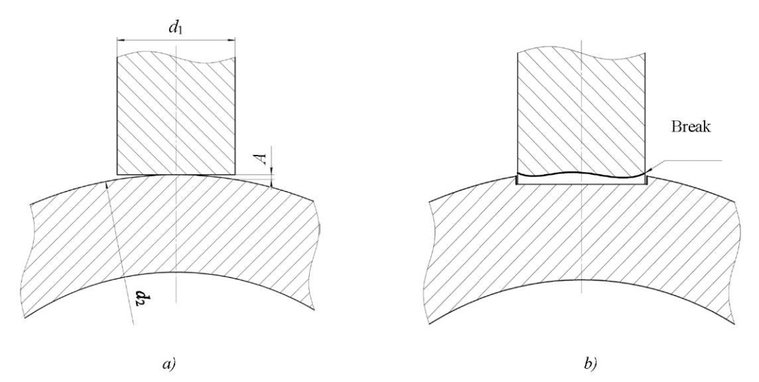
Fig. 2. Fitting unit simulators:
a — T-joint simulator;
b — connection with pre-grooving:
d1 — fitting simulator diameter;
d2 — housing simulator diameter;
А — gap
Quality control showed that the assembly of the fitting and the cylindrical housing of the equipment provided that gap A, whose value varied depending on the diameter of housing d2 and fitting d1. This form of joint did not provide uniform heating of the contacting surface, which caused the formation of sections of plastic material and their slippage with violation of the weld.
Taking into account the negative results of FW at the first stage, at the second stage, a friction welding procedure with preliminary grooving on the body (Fig. 2 b) was proposed and worked out. As the experimental results showed, at the initial stage of welding, the annular part was heated, the alignment was disturbed, and the subsequent separation of the lower part of the fitting simulator occurred, which ultimately caused the formation of a shapeless welded joint.
In the course of the experimental studies, it has been established that to obtain a high-quality weld of a large thickness base with a certain radius of curvature and a thick-walled fitting of small diameter obtained through friction welding, it is required:
The analysis of the experimental data obtained indicates the need to develop a design of the connected surfaces to provide more uniform heating and the formation of a high-quality connection under FW. The conical shape of the surfaces was chosen as one of the options for obtaining such a compound [12–15].
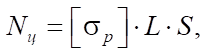
In the process of selecting the optimal contact surface, a verification calculation of the strength of welds of cylindrical and conical shapes was performed (Fig. 3). Calculations for the cylindrical surface were performed according to formula [16]:
 (1)
(1)
Where  — tensile strength, MPa; L — weld length, mm; S — weld thickness, mm.
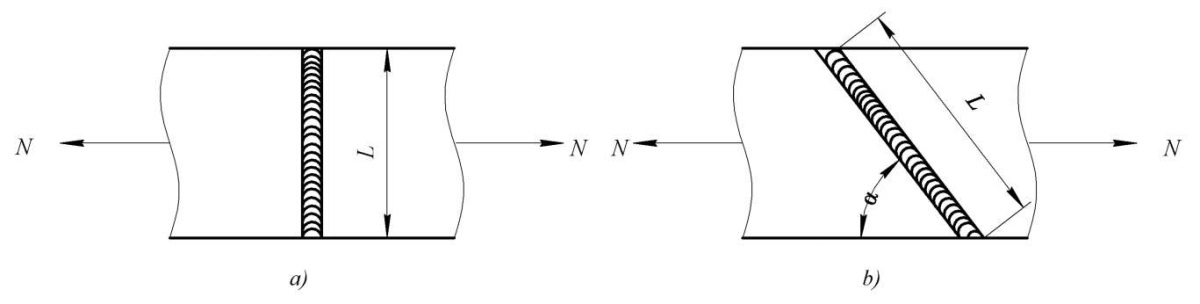
Fig. 3. Types of weld joints:
a — cylindrical connectable surface;
b — conical connectable surface:
N — load; L — weld length; α — angle of connectable surfaces
Calculations for the conical surface were performed according to formula:
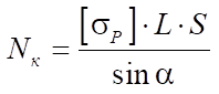 (2)
(2)
It can be seen that the shortest weld joint and the destructive load rate is characteristic of a model with a cylindrical contact surface. When moving to the conical contact surface, the length of the weld joint and the destructive load rate N naturally increase. These characteristics depend directly on angle α, whose optimal range, according to the calculation results, is presented in Table 1.
Table 1
Influence of angle of inclination α on strength indicators
|
Connection type |
Angle of inclination, α,º |
Load N, N |
|
Cylindrical |
– |
59,283 |
|
Conical |
30 |
118,566 |
|
32.5 |
110,396 |
|
|
35 |
101,609 |
|
|
37.5 |
97,396 |
|
|
40 |
94,959 |
Note that an unreasonable change in value α both up and down causes a decrease in strength (with a decrease in the weld length), or an increase in overheating and the amount of welding deformations (with an increase in the weld length).
In this regard, it is proposed to use a conical contacting surface on the one hand — on the fitting, on the other — a reciprocal conical surface on the housing (Fig. 4 a)
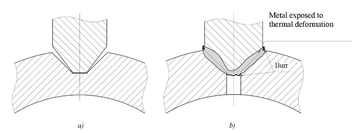
Fig. 4. Fitting unit:
a — shape of the contact surface; b— ompleted weld
This design provides performing welds regardless of the diameter of the housing, since ductile metal fills the connected surface evenly under welding (Fig. 4 b).
Since the developed design provides uniform filling of the weld preparation regardless of the shape of the housing, it was proposed to use a flat surface of the housing for further experimental studies. The design and manufacture of models of fittings with different angles of the conical surface was carried out (Fig. 5).
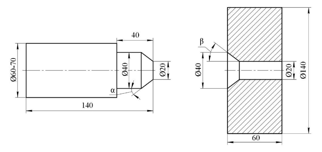
Fig. 5. Fitting unit model:
α — fitting cone angle; β — housing cone angle
The dimensions of the angles of the mating surfaces of the joint were selected taking into account the calculation results, as well as the energy capacity of the MST-41 welding machine and the expected dimensions of the weld [18].
When preparing the surfaces of model elements for welding with cone angles α = 30.0°; 32.5°; 35.0°; 37.5° and 40.0°, welds were formed qualitatively with reasonably selected parameters of the FW mode. At the same time, the highest quality connection was obtained with a surface angle of 37.5°.
In the course of experimental studies, a pattern was established in the formation of a weld, namely, a gradual process of friction, heating, and plastic deformation took place on the surface of the welded joint. These differences from the known methods of forming joints in FW did not allow using the classical cyclogram of the welding process [11]. This required a more detailed study of the sequence of formation of the compound and the description of the cyclogram of the process in accordance with the specifics (Fig. 6).
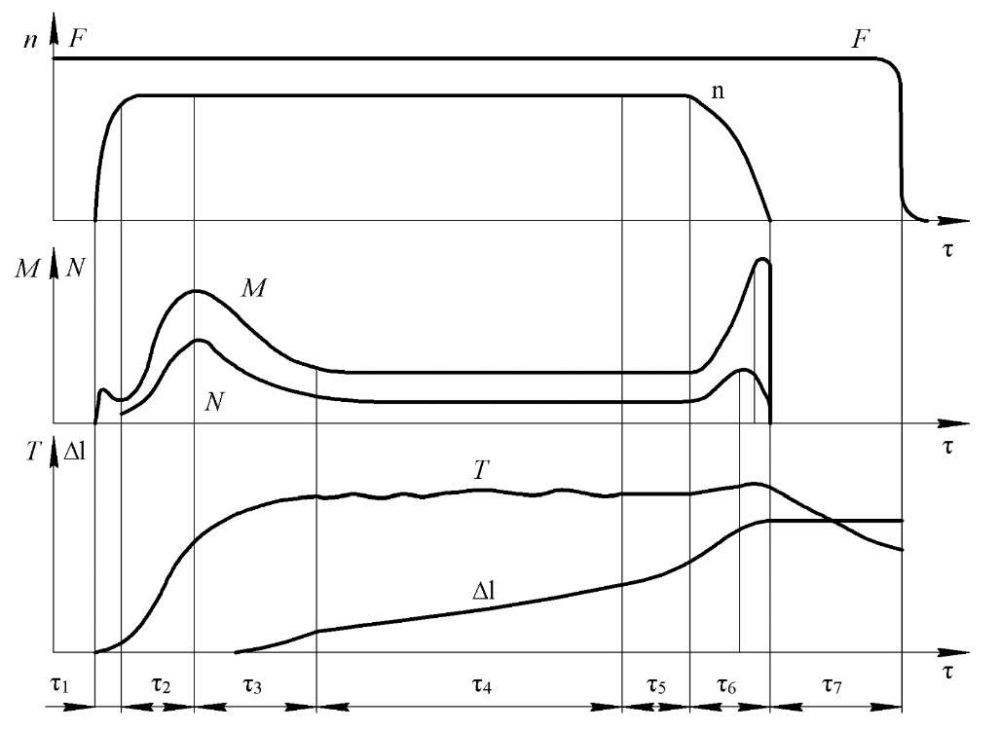
Fig. 6. FW process cyclogram:
n — angular velocity;
F — heating pressure;
M — friction moment;
N — heat generation power;
T — temperature in the connection zone;
∆l — upsetting;
τ1–τ7 — cycle phases
In the welding process, phases τ1, τ2, τ3 are similar to the initial phases of the FW cylindrical surfaces. In the first phase, the surface is lapped with separate microirregularities, but, unlike the classical methods, lapping does not go over the entire surface, but only on the area in contact with the cone. In the second phase, there is an increase in the area of the contacting surfaces and, as a result, temperature rise. The third phase is characterized by a rise in temperature and the release of plasticized metal (burr). The fourth phase τ4 — phase of sequential heating of the entire cone surface. In this phase, there is a partial repetition of the processes occurring in the second and third phases. The difference is that the areas entering the heating process are already partially warmed up. In the fifth phase τ5, a process of uniform heating of the entire welded surface occurs, close to a quasi-stationary state. The sixth τ6 and seventh τ7 — the braking and forging phases, in which the process of complete stop of rotation and compression occurs.
The implementation of this cyclogram is possible using the developed technique for calculating the parameters of the friction welding mode [17]. The basic parameters include: welding time tc, heating pressure Рн, rotation speed V, and forging pressure Рп. The calculation results are shown in Table 2.
Table 2
Parameters of FW process of fitting model
|
Material |
Sample number |
Heating pressure, MPa |
Forging pressure, MPa |
Rotation speed, rpm |
Welding time, sec. |
|
10GN2MFA Steel |
10–1 |
0.323 |
0.539 |
1,200 |
27 |
|
10–2 |
0.367 |
0.539 |
1,200 |
32 |
|
|
10–3 |
0.340 |
0.539 |
1,200 |
30 |
It is possible to significantly reduce the heating pressure and increase the welding time due to the sequential inclusion of annular sections of the conical surface of the connected parts in the heating stage.
The proposed process solutions make it possible to obtain high-quality connections with lower operating parameters, which reduces heat input in the weld, providing a reliable connection and minimal grain growth. In addition, with this method of welding, the annular sections entering into heating at the point of friction have a layer of ductile metal from the previous layer, which acts as a lubricant. This reduces the friction coefficient, and thereby reduces the required power of the welding machine.
The authors carried out the control of welds by non-destructive and destructive methods. The quality control results and mechanical properties of welds are shown in Table 3. The results of hardness measurement (Fig. 7) and microstructure (Fig. 8) of the welds meet the requirements of regulatory and technical documents.3
The hardness values in all samples indicate a fairly uniform structure over the entire weld section. Hardness values corresponding to the hardness of quenching structures were not revealed. Figure 7 shows a slight increase in hardness along the fusion line. To align the values along the cross-section of the weld, it is recommended to carry out heat treatment — thermofixation.
Table 3
Results of mechanical tests, radiographic and ultrasonic inspection of the fitting welds
|
Steel grade |
Sample number |
Stress limit σв, MPa |
Yield strength σ0.2, MPa |
Relative elongation δ, % |
Relative narrowing ψ, % |
Bend angle |
Impact strength KCV, J/m² |
Control |
|
|
MAW |
UT |
||||||||
|
10GN2MFA |
10–1 |
635 |
595 |
14–17 |
70–78 |
123 |
251 |
sat |
sat |
|
10–2 |
510 |
425 |
12–16 |
67–71 |
127 |
195 |
sat |
sat |
|
|
10–3 |
770 |
650 |
15 |
68–70 |
125 |
273 |
sat |
sat |
|
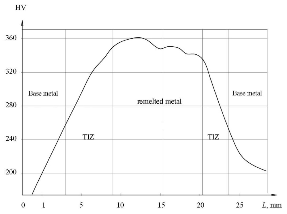
Fig. 7. Hardness distribution over the width of the weld joint made of 10GN2MFA steel
(TIZ — thermal impact zone)
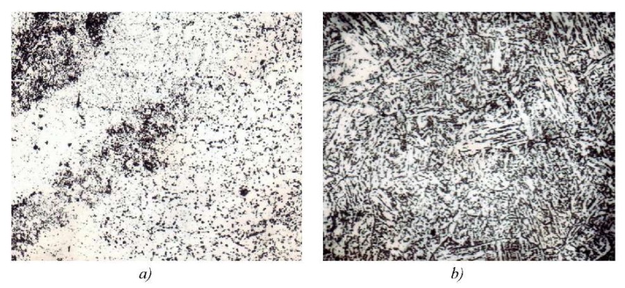
Fig. 8. Microstructure of various zones of a weld from 10GN2MFA steel
made by friction welding (×500):
a — thermal impact zone; b — fusion line
Discussion and Conclusion. High and stable quality of the weld is obtained due to optimal heat input under friction welding of the contacting surfaces through the sequential including of the annular sections of the conical welds in the heating and friction process. This contributes to the metal structure refinement of the weld and the thermal impact zone, and obtaining high mechanical properties of the metal of the weld.
As a result of the experimental study, the positive effect of the basic structural and processing factors and, above all, the conical shape of the connected surfaces, on the quality of thick-walled welds of small diameter fittings (up to 80 mm) was established. The obtained positive results of destructive and non-destructive testing confirm the required quality and prospects for the use of friction welding of fitting welds with a conical surface in the manufacture of NPP equipment.
1. Basic Provisions on Welding and Surfacing of Components and Structures of Nuclear Power Plants, Experimental and Research Nuclear Reactors and Installations 1513-72. URL: https://docs.cntd.ru/document/564412851 (accessed: 02.08.2023). (In Russ.)
2. Federal norms and rules in the field of the use of atomic energy. Welding and surfacing of equipment and pipelines of nuclear power plants NP-104-18. Order of the Federal Service for Environmental, Technological and Nuclear Supervision No. 554, dated 14.11.2018. URL: https://sudact.ru/law/prikaz-rostekhnadzora-ot-14112018-n-554-ob/np-104-18/ (accessed: 02.08.2023). (In Russ.)
3. Testing rules of metal for equipment and pipelines of nuclear power plants during manufacture and installation. NP-105-18. Order of the Federal Service for Environmental, Technological and Nuclear Supervision No. 553, dated 14.11.2018. (In Russ.)
1. Sabitov MKh, Ponikarov SI, Valeev SI. Assessment of the Resource of Safe Operation of Gas Separators with Defects in Fillet Weld Fitting Welding. Herald of Kazan Technological University. 2013;16(15):118–120. https://cyberleninka.ru/article/n/otsenka-resursa-bezopasnoy-ekspluatatsii-g-azoseparatorov-s-defektami-uglovyh-svarnyh-shvov-privarki-shtutserov/viewer (accessed: 20.08.2023). (In Russ.)
2. Ermolaev VV, Zhuchenko LA, Lyubimov AA, Gladshtein VI, Kremet VL. Experience in Reconstructing the PT-60-90 Turbine Reconstruction of the Turbine PT-60-90 by Reconditioning Heat Treatment of the High-Pressure Cylinder Shell. Thermal Engineering. 2018;(6):5–14. https://doi.org/10.1134/S004036361806005X
3. Mironova LI, Fedik II. Local Thermal Loading of Two Intersecting Cylindrical Rotational Shells with a Variable Wall Thickness. Engineering and Automation Problems. 2015;(1):83–87.
4. Elchaninov AA, Korchagin IB. Design of a Device for Welding Fittings to a Heat Exchanger. In: Collection of Works of the Winners of the Competition of Research Works of Students and Graduate Students of VSTU in Priority Areas for the Development of Science and Technology. Voronezh: Voronezh State Technical University; 2020. P. 224–226. https://studfile.net/preview/16729056/page:23/ (accessed: 28.08.2023). (In Russ.)
5. Dolgachev YuV, Pustovoit VN. Interaction of Ferromagnetically Ordered Clusters with Dislocations in Austenite and Twinning. Materials Science Forum. 2022;1052:134–139. https://doi.org/10.4028/p-a8jty9
6. Assaulenko SS, Lyudmirsky YG, Kharchenko VY, Chernogorov AL. Computer-Digital Technique for Evaluating the Geometry of the Interface of the Weld with the Base Metal. IOP Conference Series: Materials Science and Engineering. 2020;1001:012038. https://doi.org/10.1088/1757-899X/1001/1/012038
7. Cleiton Carvalho Silva, Arlindo Braga de Souza Neto, Francisco Diego Araruna da Silva, Francisco Edval Sampaio de Freitas Júnior, Jesualdo Pereira Farias. Welding of ASTM A106 Gr. B Steel Pipes for High-Temperature Service — Part 1 — Residual Stress Analysis. Welding International. 2009;23(4):270–281. https://doi.org/10.1080/09507110802543476
8. Maodong Kang, Ming Jiang, Soumya Sridar, Wei Xiong, Zhixiong Xie, Jun Wang. Effect of Multiple Repair Welding on Crack Susceptibility and Mechanical Properties of Inconel 718 Alloy Casting. Journal of Materials Engineering and Performance. 2022;31(1):254–261. https://doi.org/10.1007/s11665-021-06173-6
9. Kaimeng Wang, Hongyang Jing, Lianyong Xu, Lei Zhao, Yongdian Han, Kai Song, et al. Fracture Mechanism of a Ni-Base Alloy under High-Temperature Cyclic Deformation: Experiments and Microstructure Characterization. Materials Characterization. 2022;189:111944. https://doi.org/10.1016/j.matchar.2022.111944
10. Lyudmirskii YuG, Assaulenko SS, Ageev SO. Constructive and Technological Method of Increasing Durability of “Choke Connections”. Journal of Physics: Conference Series. 2021;2131:042061. https://doi.org/10.1088/1742-6596/2131/4/042061
11. Gnyusov SF, Khazanov IO, Sovetchenko BF, Degtyarenko EA, Kiselev AS, Trushchenko EA, et al. Application of the Effect of Superplasticity of Steels in Tool Production. Monograph. Tomsk: NTL Publishing House; 2008. 240 p. (In Russ.)
12. Poletaev YuV, Poletaev VYu, Shchepkin VV. Friction Welding of Fittings and Nozzles from Low-Alloy Steel 15Х2НМFА. Welding International. 2020;34(1–3):29–33. https://doi.org/10.1080/09507116.2021.1919446
13. Shchepkin V, Poletaev Yu. Friction Welding of Fasteners from Austenite Steels. E3S Web of Conferences. 2020;210:08012. https://doi.org/10.1051/e3sconf/202021008012
14. Schepkin V, Poletaev Yu. Friction Welding of Carbon Quality Steel. Journal of Physics: Conference Series. 2021;2131:042062. https://doi/org/10.1088/1742-6596/2131/4/042062
15. Poletaev YuV, Poletaev VYu, Shchepkin VV. Friction Welding of Fittings and Branch Pipes from Low-Alloy Steel 15Kh2NMFA. Welding Production. 2018;(7):13–18. (In Russ.)
16. Konovalov AV, Kurkin AS, Makarov EL, Nerovnyi VM, Yakushkin BF. Theory of Welding Processes. VM Nerovnyi (ed). Moscow: Bauman University Publ. House; 2007. 752 p. (In Russ.)
17. Shchepkin VV, Poletaev YuV, Rogozin DV. Method for Calculating the Parameters of the Friction Welding Mode of Conical Connections. In: Proc. XXIV Int. Sci.-Pract. Conf. within the Framework of the Agro-Industrial Forum of the South of Russia, Exhibitions “Interagromash”, “Agrotechnologies”. Rostov-on-Don: DSTU-PRINT; 2021. P. 490–493. https://doi.org/10.23947/interagro.2021.490-493 (In Russ.)
Yuri V. Poletaev, Dr.Sci. (Eng.), Senior Research Fellow, Professor of the Welding Fabrication Machines and Automation, ScopusID
1, Gagarin sq., Rostov-on-Don, 344003
Viktor V. Shchepkin, Teaching assistant of the Welding Fabrication Machines and Automation, ScopusID
1, Gagarin sq., Rostov-on-Don, 344003
Poletaev Yu.V., Shchepkin V.V. Advantages of Friction Welding of Fittings with Small Diameter Conical Contact Form. Advanced Engineering Research (Rostov-on-Don). 2023;23(4):376-386. https://doi.org/10.23947/2687-1653-2023-23-4-376-386. EDN: LFCYNM


Advanced Engineering Research (Rostov-on-Don)
ISSN 2687-1653 (Online)
Contact with: Publisher / Editorial Office of the Journal
Publisher: Don State Technical University - DSTU, Rostov-on-Don, Russia - https://donstu.ru/en/
Editor-in-Chief: Alexey N. Beskopylny, Dr.Sci. (Eng.), Professor, Vice-Rector, Don State Technical University (Rostov-on-Don, Russia)
Don State Technical University
1, Gagarin Sq., Rostov-on-Don, 344003, Russia
tel.: +7 (863) 2738-372, e-mail: vestnik@donstu.ru
16+
Processing of personal data


