


Contents
Scroll to:
https://doi.org/10.23947/2687-1653-2024-24-1-48-57
EDN: IJMIOY
Scroll to:
Introduction. Improving the calculation methods of mechanical engineering facilities is an urgent and in-demand task. This fully applies to the techniques of calculating the strength of all-welded gastight boiler structures. Normative calculation techniques are based on simplified models that give limited possibilities for optimizing these structures. The low calculation accuracy inherent in such techniques is unacceptable under real design conditions, when an engineer is faced with the task of developing competitive structures in a short time, i.e., reducing metal consumption while providing the strength of these structures with limited development time. The use of simplified models was justified in the past, under conditions of insufficient development of computer technology. Application of the most advanced techniques based on computer modeling makes it possible to increase the accuracy of calculations, provide the optimization of such structures, and improve the quality of design. The objective of this study was to develop a new special procedure for calculating the strength of all-welded gastight structures based on computer modeling, using the most advanced methods of modeling the membrane wall and factors affecting it. The accompanying task was to verify the developed procedure based on comparing the results of calculations using the developed technique and the normative method.
Materials and Methods. The developed technique is based on the replacement of the membrane wall with an orthotropic plate or shell. Computer modeling was used applying the finite element method of all-welded gastight structures, and the impacts to which they were subjected during operation, as well as an effective method for assessing the technical condition of these structures.
Results. A new two-stage technique for calculating the strength of increased accuracy of all-welded gastight boiler structures was developed and patented. The calculation results were compared according to the proposed procedure and the normative method. It was shown that the proposed technique made it possible to increase the accuracy of modeling and calculation. The error in calculating all-welded gastight structures of a high-power boiler was reduced by more than 30% for the recommended steps between stiffeners. For specially reinforced membrane walls with steps exceeding the permissible values, the error reduction reached 70% or higher.
Discussion and Conclusion. The developed technique is used in the modeling and calculation of all-welded gastight structures. Its application makes it possible to optimize the step between the stiffeners of the structure of the support and connecting nodes of gastight membrane walls. Based on the results of the application of the two-stage calculation procedure, new designs were developed and patented. The developed technique has been used in the real design of boilers since 2014.
Kurepin M.P., Serbinovskiy M.Yu. Application of Special Calculation Techniques in the Design of All-Welded Gastight Structures of Boiler Units. Advanced Engineering Research (Rostov-on-Don). 2024;24(1):48-57. https://doi.org/10.23947/2687-1653-2024-24-1-48-57. EDN: IJMIOY
Introduction. The normative technique of the strength calculation of all-welded gastight structures1 is based on replacing the screen with a structurally orthotropic Kirchhoff-Love plate with considerable simplifications. In this model, the orthotropy of the plate properties is taken into account only when calculating bending forces. The major objective of the introduced simplifications is to reduce the complexity of calculation formulas and, ultimately, the overall complexity of calculations. The models underlying the technique include a gastight screen in the form of an orthotropic plate, stiffener rings in the form of constant-section beams, and fasteners in the form of connections between the wall and the stiffener rings.
The following assumptions are made in the model2:
A significant disadvantage of this scheme is the use of simplified models that do not fully take into account the reinforcing, attached and other structural elements, their cross impact, as well as the effect of all influencing factors causing a complex stress-strain state of the membrane wall. This technique has limited modeling capabilities, specifically for membrane walls of complex shape, for which it is not applicable.
There are limits to the application of normative calculation formulas, constraining them due to design or loading features3. For membrane walls, standard calculation formulas are not applicable for any cross-sections, except for a pipe with a flat spacer. They are not applicable for membrane walls of complex shape. The maximum step size between stiffener rings is limited. It is noted in the normative technique that it is allowed to use other methods of calculating the strength of all-welded membrane structures, subject to providing the normative strength reserves. The technical regulations of the Customs Union enable using a number of calculation methods in addition to regulatory formulas, including computer modeling4. In regulatory documents, the strength calculation techniques that go beyond the application of regulatory formulas are called alternative, or special. In connection with the above, the objective set by the authors of this article — to develop a new special method for calculating all-welded gastight structures using computer modeling, which allows for high accuracy and reliability of modeling and calculation results — seems highly relevant.
In the papers of Russian authors, models have already been proposed in which the membrane wall is replaced by a statically indeterminate frame. Special calculation methods are successfully used to assess the strength and resource of elements of boilers and power plants [1]. In the studies devoted to the calculation of gastight membrane walls, it is noted that the methods based on the use of modern achievements in the area of numerical methods using computer modeling are promising [2].
Recent studies on boiler membrane walls include the works of Milošević-Mitić [3], Nagiar [4], Sertić [5], who proposed a method for calculating boiler strength and determining temperature displacements and loads of supports based on the Kirchhoff-Love theory and computer modeling using the finite element method (FEM) [6]. However, this technique is characterized by an increased error due to the application of significant simplifications in the membrane wall model (e.g., pipes are replaced with absolutely rigid bodies) [7]. The method of reverse transition from the plate to the wall and assessment of its technical condition has not been proposed [8].
High calculation accuracy was obtained through modeling membrane walls based on the general mechanics of a deformed solid and measurements in numerical experiments with accurate solid-state models of the screen [9]. Effective methods for modeling loads [10] acting on all-welded gastight structures have been proposed, which make it possible to increase the accuracy and reliability of modeling these structures [11].
In general, modeling membrane walls using orthotropic plates is relevant if we take into account the complexity of modeling and calculating membrane walls with many pipes and spacers using traditional solid-state computer simulation techniques, for which there are strict limitations. These restrictions deal with the relative dimensions of the height of the solid-state element to its length and width, which cannot exceed ⅛ (aspect ratio metric [12]), with a ratio of membrane wall thickness to its width of 1/400 or more.
When developing the new technique, the following objectives were set: increasing accuracy, reducing the complexity of modeling and calculation, reducing the time of computational operations during optimization and evaluation of strength, rigidity, stability, and durability of structures. It is known that membrane walls operate under conditions of complex resistance and are simultaneously exposed to external forces, moments, pressure or rarefaction from the inside of the boiler, pressure in pipes, an uneven temperature field, taking into account the cyclic effect of these parameters and creep of materials at high temperatures. An additional, but rather important task of this development was to create a convenient tool for cyclic optimization of the structure, which includes visualization of the results of making changes to the structure in the form of stress, strain, and displacement fields.
Materials and Methods. The technique proposed by the authors involves replacing the membrane wall with an orthotropic plate or shell. The membrane wall has a regular structure and a section that periodically changes in the direction perpendicular to the pipes. Such a membrane wall can be considered as a structurally orthotropic plate, i.e., a plate in a flat stressed state with elastic characteristics that differ in mutually perpendicular directions. The membrane wall is a plate, and the bent screen is a shell since the diameter of the pipes, which determines the thickness of the screen, is small compared to its other dimensions. The structural elements of a gastight boiler, which can be represented as structurally orthotropic plates, are, first of all, membrane walls of the furnace, the transition flue, the convective shaft of the boiler, and membrane superheaters.
The authors previously developed a two-stage modeling and calculation technique for all-welded gastight structures, which received a patent for the invention [13]. It is based on the replacement of the membrane wall with an orthotropic plate or shell, reliable modeling of all-welded gastight structures and the impacts to which they are exposed during operation, and on an effective method for assessing the technical condition of these structures. Through the developed technique, there are opportunities to optimize structures and reduce their metal consumption [14], which have not existed before. New designs are worked out, the complexity of design is significantly reduced [15]. The problem of assessing the technical condition of boiler structures containing membrane walls is solved by applying the most advanced modern practices based on achievements in numerical modeling.
The method of calculating the strength of all-welded gastight structures consists of two stages. At the first stage, a model of a box structure with screens in the form of orthotropic plates and/or shells is formed with a preliminary calculation of their dimensional and physico-mechanical characteristics. The attached elements, including pipe connectors with headers, festoons, stiffener rings, various fasteners, supports, reinforcement elements are modeled in the form of rods, shells, connections, and boundary conditions. Then, local zones of orthotropic plates and/or shells with increased displacements and deformations are determined, and the technical condition of the attached elements is assessed. At the second stage, models are formed for places with exceeding the specified parameters, in which local zones of screens with attached elements with increased displacements, stresses, and deformations are modeled by solid-state elements (submodeling of local zones [12]). Conditionally elastic analysis is carried out. Health assessment in critical sections is provided according to static strength conditions and optimization of the structure.
Research Results. The calculation of all-welded gastight boiler structures with a steam capacity of 810 tons of steam per hour (TPE-360/T model) with dimensions of 14.48×14.24 m was performed. In the course of the work, the authors compared the calculation results using the proposed procedure and the normative method.
Initial data for the calculation: the boiler membrane walls were welded from a 60×6 mm pipe of steel 20 with flat spacers 80 mm wide, made of sheets of steel 20 with a thickness of 6 mm. The membrane wall was exposed to heating from a furnace with a cooling medium in pipes with the following parameters: 16.3 MPa, 349°C (Fig. 1). The calculation was carried out for buckling 3,000 Pa and emergency rarefaction 5,000 Pa.
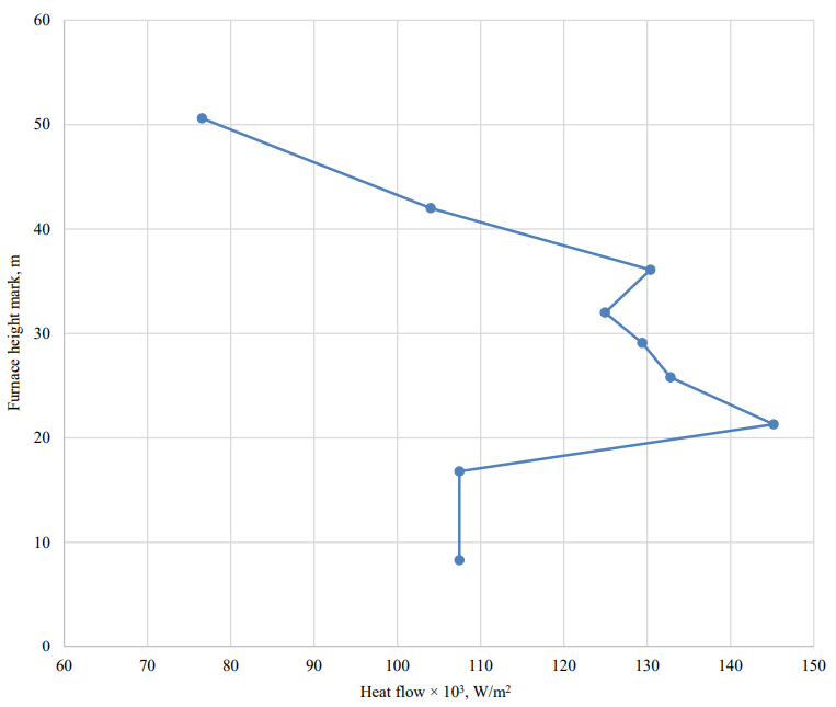
Fig. 1. Initial data for the calculation: heat flow perceived by the screen surface
The calculation was carried out in accordance with the requirements and formulas of normative documents (“Calculation standards for the strength of stationary boilers and steam and hot water pipelines”, “Calculation and design of fastening elements of the screen system of boiler units with all-welded panels”, “Technical Regulations of the Customs Union”).
The permissible step between the stiffener rings, according to the calculation results, is 4,012 mm at the furnace level and 4,050 mm in the upper part of the furnace at marks 16.8 and 50.6, respectively.
The calculation of the boiler box using the technique presented in this paper was performed in two stages. The model of the first stage included gastight screens of a furnace, a convective shaft, a gas reversing chamber, an aerodynamic nose, and a ceiling superheater, made in the form of shells with elasticity parameters calculated using numerical methods [9]. The stiffener rings, festoons No. 1 and No. 2 with suspensions, suspensions of boiler screens, wall superheater were modeled with beam-rod elements (Fig. 2). When comparing the results of the two calculations, it was reported that the problem areas of the structures, determined by the first stage of modeling, converged with the design points of the standard calculation: in the middle of the screen under the stiffener rings (point No. 1, Fig. 2 C), in the corner of the furnace between stiffener rings (point no. 2, Fig. 2 B). At the same time, the new technique based on a more advanced model of the boiler box made it possible to take into account the following technical solutions applied in the design of the boiler box and aimed at optimizing and strengthening it: design of corner bracing in the form of lever mechanisms that allow the force to be transmitted strictly along the axis of the adjacent screen; intermediate fasteners reinforced with combs-ribs, providing free thermal expansion of the screen; longitudinal ribs under the stiffener rings in places where the standard values of the steps between the stiffener rings are exceeded [15]; special designs of stiffener rings [16]; angle brackets; seal boxes]. In addition, the model made it possible to take into account the effect of a wall-mounted radiant superheater (attached to the screens through welding), festoons, stiffen boxes, and other structural elements.
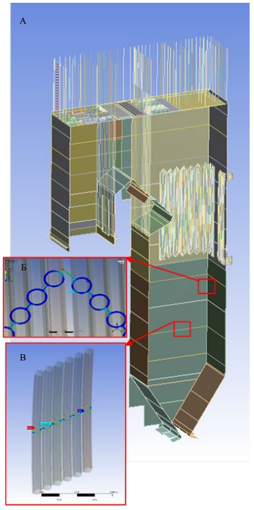
Fig. 2. Calculation of the boiler box of TPE-360/T model according to the developed technique:
A — shell-rod model (first stage of modeling); B — solid molel of the box corner (second stage of modeling); C — solid molel of the midpart of the screen under the stiffener (second stage of modeling)
The model includes structures of a ceiling superheater, an aerodynamic nose, a convective shaft, a gas reversing chamber, and other elements, whose technical condition is difficult to assess using the normative technique due to its limitations. The permissible step between the stiffener rings, according to the calculation, is 4,500 mm at the furnace level, and 6,000 mm at the top of the furnace, which is higher than the values obtained through the normative technique.
Thus, it can be concluded that the impact of design solutions aimed at optimizing and strengthening the boiler box (without increasing the number of stiffener rings) is significant. The results of the calculation according to the normative technique, which does not allow taking into account these decisions, are excessively conservative. The calculation results using the proposed method are more reliable, as they enable us to fully take these decisions into account.
A comparison of the calculation results obtained through different methods was carried out at two characteristic points of the structure specified in the normative technique: point 1, for which the influence of attached and reinforcing elements is minimal, at the calculated point 2, for which the influence of reinforcing elements is most significant (Table 1).
Table 1
Calculated stresses in screen sections according to the normative and new technique, MPa
|
Design section, mark, m |
16.8 |
50.6 |
||
|
Permissible stresses in the cross section of 1–2 screen, MPa |
149.8 |
152.6 |
||
|
Permissible stresses in the cross section of 5–6 screen, MPa |
158.4 |
161.8 |
||
|
Calculated combination of loads: weight, overpressure in pipes, buckling in the furnace space |
||||
|
Setting-out point according to the requirements of the normative technique |
1* |
2** |
1* |
2** |
|
Equivalent stresses in the cross section of 1–2 screen according |
119.3 |
121.7 |
141.4 |
145.9 |
|
Equivalent stresses in the cross section of 5–6 screen according |
10.4 |
97.0 |
21.9 |
175.9 |
|
Equivalent stresses in the cross section of 1–2 screen according |
135.6 |
109.2 |
149.0 |
114.4 |
|
Equivalent stresses in the cross section of 5–6 screen according |
18.1 |
55.4 |
27.4 |
92.8 |
|
Calculated combination of loads: weight, overpressure in pipes, emergency rarefaction in the furnace space |
||||
|
Permissible stresses in the cross section of 1–2 screen, MPa |
199.8 |
203.5 |
||
|
Permissible stresses in the cross section of 5–6 screen, MPa |
217.8 |
222.5 |
||
|
Equivalent stresses in the cross section of 1–2 screen according to the normative technique, MPa |
138.6 |
142.7 |
175.8 |
183.4 |
|
Equivalent stresses in the cross section of 5–6 screen according to the normative technique, MPa |
15.6 |
160.5 |
31.1 |
289.3 |
|
Equivalent stresses in the cross section of 1–2 screen according to the developed technique, MPa |
147.6 |
109.6 |
182.8 |
109.0 |
|
Equivalent stresses in the cross section of 5–6 screen according to the developed technique, MPa |
19.1 |
87.8 |
30.9 |
125.8 |
|
* in the middle of the wall, between the stiffener rings |
||||
|
** in the corner of the box |
||||
At point 1, a good coincidence of the results was obtained — with respect to the permissible stresses, the voltage difference was no more than 11%. At point 2, the stress difference ranged from 33% for small and medium steps between the stiffener rings to 73% for large steps between the stiffener rings. High stress values in all cases were given by the normative technique.
The proposed method and model increase the reliability of simulating the behavior of the structure and the accuracy of the calculation. One of the results of the calculations and optimization of the design is the distribution of stiffener rings according to the height of the boiler furnace of TPE-360/T model. Table 2 shows the results of calculating the step of stiffener rings: 1 — according to the normative technique, without taking into account the design features; 2 — according to the calculation results using the developed techniques that provide more reliable simulation of the behavior of the structure, taking into account the influence of all its elements, including additional reinforcing elements in the form of stiffener rings, etc.
Table 2
Calculated and accepted steps between the stiffener rings
|
Design section - 1, m |
8.3 |
16.8 |
21.3 |
25.8 |
29.1 |
32 |
36.1 |
42 |
50.6 |
|
Maximum permissible step between stiffener rings - 2, mm |
4,012 |
4,012 |
3,961 |
3,974 |
3,979 |
3,971 |
3,962 |
4,000 |
4,050 |
|
The adopted step between the stiffener rings following the results of design optimization, mm |
2,660 |
4,500 |
4,400 |
4,250 |
2,700 |
3,520 |
3,300 |
3,500 |
6,000 |
|
Fulfillment of the strength conditions for the accepted step (yes/no) |
yes |
yes |
yes |
yes |
yes |
yes |
yes |
yes |
yes |
|
1 — mark for the height of the furnace, where 0 — the floor level |
|||||||||
|
2 — as per calculation according to the normative technique |
|||||||||
It can be observed that the use of special calculation methods makes it possible to avoid the installation of additional stiffener rings for at least two characteristic places of the boiler furnace: at the place of installation of the burners (marks from 16.8 to 25.8 m) and at the place of the reversing flue (50.6 m mark). This avoids overspending of metal and complication of the structure due to the difficulties of simultaneous placement of burner devices and stiffener rings, and elements of the reversing flue.
An assessment of the metal consumption was carried out. In this case, the weight of one stiffener ring with fasteners is on average 3,500 kg. To meet the requirements of the regulatory calculation for the step between the stiffener rings, it is required to install at least three additional stiffener rings at the furnace height from 16.8 to 25.8 m and 50.6 m. The total metal consumption of such a constructive solution is 10,500 kg. Thus, the use of new special calculation techniques provides ample opportunities for optimization and reduction of metal consumption while maintaining sufficient strength of all-welded gastight boiler structures.
Discussion and Conclusion. A new technique for calculating and analyzing the technical condition and optimization of membrane wall structures of boiler units has been developed on the basis of modern, most effective methods of mathematical modeling of membrane walls with equivalent orthotropic plates, calculation of their geometric and physico-mechanical parameters, special loads and impacts inherent in all-welded gastight structures. The use of new special calculation techniques provides ample opportunities for optimization and reduction of metal consumption while maintaining sufficient strength of all-welded gastight boiler structures.
The results of verification of the replacement of membrane walls with orthotropic plates were compared to the results of field experiments on determining the angles of rotation of the vertices of the ribs under the action of a unit moment. They showed that the displacement error did not exceed 14% for shell models implemented through the proposed technique. At the same time, solid-state models give an error of up to 10%, i.e., slightly less when the number of finite elements of the models is an order of magnitude larger (and the dimension of the model is up to 100 times higher, depending on the type of element — linear or quadratic). This modeling error fully meets the requirements of modern design, since the errors associated with manufacturing tolerances are in the range of 10–15% of the wall thicknesses of pipes, sheets, and the weld leg [9].
The significant disadvantages of the normative technique are the scant possibilities for optimizing the design and strength requirements in other ways, except for increasing the number of stiffener rings, which significantly increases the metal consumption and causes growth of cost. This means that simplified models adopted in the normative calculation at the time when computer engineering was insufficiently developed, limit the possibilities of optimizing structures in modern design. This necessitates using special calculation techniques based on numerical computer modeling.
The technique proposed by the authors during the actual design of boiler units has shown its high accuracy and efficiency, wide possibilities for optimizing the design, reducing metal consumption under maintaining sufficient strength, the ability to significantly reduce the complexity of model formation and machine calculation time. In addition, the reliability of behavioral modeling and calculation accuracy of all-welded gastight structures have been increased through the use of modern numerical simulation techniques. They provide most accurate accounting of the features of structures and their cross impact, and the effect of all influencing factors, as well as calculating screens of complex shape. Through the developed techniques, the calculation error has been reduced by more than 30% for the recommended steps between the stiffener rings. For specially reinforced membrane walls with steps exceeding the permissible values, the error reduction reaches 70% or higher.
The application of the proposed technique makes it possible to decrease the number of finite elements of models of structures with screens by several orders of magnitude compared to similar solid-state models of the screen, reduce the complexity of forming models of structures with screens. The time of computational operations in calculating the stress-strain state of all-welded gastight structures is significantly improved. And finally, the complexity of modeling and calculation is significantly reduced while maintaining sufficient accuracy [13].
The authors note that the technique they developed for calculating the strength of all-welded gastight structures is generally intended for the use in the design and optimization of thin-walled structures with periodically changing cross-section and internal channels in the walls, which can be simultaneously exposed to external forces, moments. In this particular case, these are thin-walled structures made of tubular membrane walls of steam and hot water boilers, i.e., all-welded gastight structures with all structural elements attached to them, e.g., elements of the support and suspension system, fasteners, burners, blast nozzles, etc.
This technique is implemented on medium-powered personal computers and can be put into practice of real design of boiler-building enterprises and design organizations of other branches of mechanical engineering, which use plates and/or shells with regularly changing cross-sections.
The proposed technique has been used in the real design of boiler units since 2014, including power boilers Pp-1030-25.0-570/570GM, E-220-9.8-540GM, E-500-13.8-560G (model TGE-440), PP-1900-25.8-568/568 KT, E-540-13.8-560GN (model TGE-225, E-540-13.8-560GN (model TGE-224/S7), E-810-13.8-560BT (model TPE-360/T).
1. RD 10-249-98. Calculation Standards for the Strength of Stationary Boilers and Steam and Hot Water Pipelines. URL: https://docs.cntd.ru/document/1200021653 (accessed: 15.12.2023) (In Russ.).
2. RTM 24.031.06-73. Calculation and Design of Fastening Elements of the Wall System of Boiler Units with All-welded Panels: Technical Guides. Leningrad: RIO NPO TsKTI; 1974. 39 p. (In Russ.).
3. GOST 34233.1-2017. Vessels and Devices. Norms and Methods of Strength Calculations. Moscow: Standartinform; 2019. 30 p. (In Russ.).
4. CUTR 032/2013. Technical Regulations of the Customs Union. On the Safety of Equipment Operating under Excessive Pressure. URL: http://docs.cntd.ru/document/499031170 (accessed: 15.12.2023) (In Russ.).
1. Kurepin MP, Serbinovskiy MYu, Kolesnikov AA, Dotsenko VE. Using 3D Modeling in an Automated System for Diagnosing the Technical Condition, Assessing the Strength and Resource of Components of Boilers and Power Plants. In: Proc. II Int. Sci.-Tech. Conf. “Diagnostics and Forecasting of the Technical Condition of Power Plant Equipment”. Moscow: “VTI” OJSC; 2021. P. 48–54. (In Russ.).
2. Kurepin MP, Serbinovskiy MYu. Efficient Methods of Finite-Element Analysis of Energetic Machinery Complex Structures. Modern High Technologies. 2017;(10):19–25. URL: https://top-technologies.ru/ru/article/view?id=36822 (accessed: 15.12.2023). (In Russ.).
3. Gaćeša B, Milošević-Mitić V, Maneski T, Kozak D, Sertić J. Numerical and Experimental Strength Analysis of Fire-Tube Boiler Construction. Tehnicki vjesnik — Technical Gasette. 2011;18(2):237–242. URL: https://www.researchgate.net/publication/265201672_Numerical_and_experimental_strength_analysis_of_fire-tube_boiler_ construction (accessed: 15.12.2023).
4. Nagiar HM, Maneski T, Milošević-Mitić V, Gaćeša B, Andelić N. Modeling of the Buckstay System of Membrane-Walls in Watertube Boiler Construction. Thermal Science. 2014;18(1):59–72. URL: http://doi.org/10.2298/TSCI120204174N (accessed: 15.12.2023).
5. Konjatić P, Dautović S, Ostojić Z, Sertić J. Seismic Action Influence on the Pressure Parts of the Watertube Steam Boiler Construction. Machines. Technologies. Materials. 2019;13(5):210–213. URL: https://stumejournals.com/journals/mtm/2019/5/210.full.pdf (accessed: 15.12.2023).
6. Sertić J, Kozak D, Samardžić I. Calculation of Reaction Forces in the Boiler Supports Using the Method of Equivalent Stiffness of Membrane Wall. The Scientific World Journal. 2014;2014(3):392048. http://doi.org/10.1155/2014/392048
7. Sertic J, Kozak D, Damjanovic D, Konjatic P. Homogenization of Steam Boiler Membrane Wall. In: Proc. 7th Int. Congress of Croatian Society of Mechanics. Zagreb: Hrvatsko Društvo za Mehaniku; 2012. P. 207–208.
8. Sertić J, Gelo I, Kozak D, Damjanović D, Konjatić P. Theoretical Determination of Elasticity Constants for Steam Boiler Membrane Wall as the Structurally Orthotropic Plate. Tehnicki vjesnik — Technical Gazette. 2013;20(4):697–703.
9. Kurepin MP, Serbinovskiy MYu. Simulation and Optimization of Water-Wall Tube Panels Design for Power Boilers. MATEC Web Conferences. 2019;298:0011210. URL: http://doi.org/10.1051/matecconf/201929800112 (accessed: 15.12.2023).
10. Kurepin MP, Serbinovskiy MYu. Boiler Dry-Bottom Ash Hopper Load Calculation Methods. Modern High Technologies. 2016;(7):32–39. URL: https://toptechnologies.ru/ru/article/view?id=36059&ysclid=liolq7zv6e178655419 (accessed: 15.12.2023). (In Russ.).
11. Kurepin MP, Serbinovskiy MYu. Simulation of One-Sided Heating of Boiler Unit Membrane-Type Water Walls. Thermal Engineering. 2017;(3):60–68. https://doi.org/10.1134/S0040363617030055 (In Russ.).
12. Basov KA. ANSYS: User Reference. Moscow: DMK Press; 2014. 640 p. (In Russ.).
13. Kurepin MP, Serbinovskij MYu, Ivanenko VV. Analysis and Optimisation of Designs and Boilers with Tube-in-Sheet Shields. RF Patent No. 2 568 783 C1. 2015. URL: https://patents.s3.yandex.net/RU2568783C1_20151120.pdf (accessed: 15.12.2023). (In Russ.).
14. Serbinovskij MYu, Kurepin MP. Convective Shaft of Boiler with Node for Sealing of Passage of Vertical Pipes. RF Patent No. 2 702 3142019 C1. 2019. URL: https://patents.s3.yandex.net/RU2702314C1_20191007.pdf (accessed: 15.12.2023). (In Russ.).
15. Serbinovskij MYu, Kurepin MP. Membrane Screen of Steam Boiler. RF Patent No. 2 668 048 C1. 2018. URL: https://patents.s3.yandex.net/RU2668048C1_20180925.pdf (accessed: 15.12.2023). (In Russ.).
16. Kumar PR, Thiruselvan MG, Babu JM, Rajagopal M. Weight Optimization of Buck Stays using Castellated Beams. International Journal of Engineering and Advanced Technology (IJEAT). 2014;3(5):200–203.
Maxim P. Kurepin, lead technician designer
50A/8, bld. 4, Zemlyanoy Val St., Moscow, 109028
Mikhail Yu. Serbinovskiy, Dr.Sci. (Eng.), Professor of the Fundamentals of Machine Design Department
2, Rostovskogo Strelkovogo Polka Narodnogo Opolcheniya Sq., Rostov-on-Don, 344038
Kurepin M.P., Serbinovskiy M.Yu. Application of Special Calculation Techniques in the Design of All-Welded Gastight Structures of Boiler Units. Advanced Engineering Research (Rostov-on-Don). 2024;24(1):48-57. https://doi.org/10.23947/2687-1653-2024-24-1-48-57. EDN: IJMIOY


Advanced Engineering Research (Rostov-on-Don)
ISSN 2687-1653 (Online)
Contact with: Publisher / Editorial Office of the Journal
Publisher: Don State Technical University - DSTU, Rostov-on-Don, Russia - https://donstu.ru/en/
Editor-in-Chief: Alexey N. Beskopylny, Dr.Sci. (Eng.), Professor, Vice-Rector, Don State Technical University (Rostov-on-Don, Russia)
Don State Technical University
1, Gagarin Sq., Rostov-on-Don, 344003, Russia
tel.: +7 (863) 2738-372, e-mail: vestnik@donstu.ru
16+
Processing of personal data


