


Contents
Scroll to:
https://doi.org/10.23947/2687-1653-2024-24-1-78-87
EDN: QOELMG
Scroll to:
Introduction. Increasing the durability of gas turbine engine (GTE) blades is achieved through the use of special protective coatings on their surface. For the development of such coatings, the basic source information is the geometric profile of the blade section. To transfer a given blade cross-section profile to the appropriate CAD/CAM system or engineering analysis package, parametric modeling methods are used to automate this operation. However, the known approaches to creating a parametric model of a blade profile are not without a number of disadvantages, and a generally accepted method for creating it does not currently exist. The research was aimed at creating a technique for approximating the profile of gas turbine engine blades, convenient for use in the subsequent analysis of the operating conditions of special coatings on the surface of the blades.
Materials and Methods. When constructing parametric models of the profile of gas turbine engine blades, a method based on the orthogonal Legendre polynomials was used. This made it possible to provide high accuracy of approximation and construction of a continuous mapping for the parameters of the blade profile approximation. A Python application was created for automated processing of source profiles. It provided the calculation of the coefficients of approximating polynomials for the contour lines of the blade, visualization of the calculation results, and creation of a dxf file based on the points of approximating functions to transfer it to the CAD system. Next, geometric models of blades were used to solve the problem of a stationary aerodynamic flow around a blade. The results of solving this problem were used to study the effect of the blade profile on its cooling in an aerodynamic flow.
Results. As an example, three options of blade profiles belonging to different types of GTE were considered. It was shown that for all three studied profiles, the proposed technique provided obtaining parametric models that maintained high accuracy in constructing approximating lines, which was confirmed by the values of the determination coefficients close to unity. To illustrate the possibility of using the obtained models, examples of solving the gas dynamic problem with a potential flow around a blade in a stationary aerodynamic flow were given. The distributions of pressure and temperature on the surface of the blade were calculated using the finite element method.
Discussion and Conclusion. The calculation results show that the proposed technique of approximating the profile of the GTE blade, based on the use of orthogonal polynomials, is a convenient tool to automate the creation of a geometric model of the blade and compare different types and profiles of blades, solving the corresponding gas dynamic problems. At the same time, for a given blade profile and GTE operating conditions, it is possible to obtain the distribution of temperatures and forces acting on the surface of the blade, which is required for predicting the durability of special coatings.
Soloviev M.E., Shuleva Yu.N., Baldaev S.L., Baldaev L.Kh. Approximation of the Profile of Gas Turbine Engine Blades. Advanced Engineering Research (Rostov-on-Don). 2024;24(1):78-87. https://doi.org/10.23947/2687-1653-2024-24-1-78-87. EDN: QOELMG
Introduction. Turbine blades are the most highly loaded parts of a gas turbine engine (GTE), the durability of which mainly determines the engine overhaul time [1]. One of the ways to increase the durability of turbine blades is to apply special protective coatings on their surfaces [2]. The coating is a complex composite structure. To select materials for it and determine its optimal geometric characteristics, it is necessary to know the operating conditions of the part: the distribution of temperatures, pressures, and shear stresses on the surface of the blade.
The highest requirements are posed on the shape of the blades, as well as on the selection of materials, their manufacturing technique, and special coatings [3]. When designing special coatings, the basic initial information is the geometric profile of the surface of the part, since the parameters of the coating manufacturing process are set on its basis.
Among the characteristic elements of the profile, the following can be distinguished: chord — distance between the most distant points with a horizontal arrangement of the blade, like an airplane wing; suction side — upper part of the profile; pressure side — lower part of the profile; leading and trailing edges [4].
The shape of the blade cross-section profile is selected both on the basis of experimental studies of pilot units and actual engines [5], as well as on the results of numerical experiments on models [6]. In the course of numerical simulation, we study the task of creating a geometric model of the blade based on a given cross-section profile and transferring it to the appropriate CAD/CAM system [7], or an engineering analysis package [8], in which the parameters of the physical properties of the materials of the parts are set, the boundary conditions of the problem are determined, and calculations are performed.
Traditionally, when creating a blade drawing, its profile is described by a set of circular arcs, which is then transferred point-by-point to the module for developing a geometric model and generating a grid of finite elements. The disadvantage of this approach is that when building each new model, you have to manually create its profile in the graphical editor. In this regard, methods of parametric modeling of the blade cross-section profile are proposed to automate this operation. One of the most well-known models is the nine-parameter RATD (Rapid Axial Turbine Design) model described in [9]. At the same time, the practice of using RATD has revealed certain disadvantages inherent in this model, specifically, the inconvenience of using it when optimizing the geometry of the profile, as well as insufficient accuracy. On this basis, the authors [10] proposed a modified version of this model, which included a larger number of parameters. Methods of parametric modeling of blade cross-section profiles are also actively used in domestic practice. Thus, in [11, 12], algorithms for the automated construction of the blade profile using approximation by curves from a set of parabolas and Bezier curves of the second order were proposed. In [13], a method for designing a grid of GTE profiles based on these algorithms was described. The use of parametric models of blade profiles in solving optimization problems was considered by the authors in [14, 15].
At the same time, it should be noted that the existing methods of parameterization of the blade profile are not without a number of disadvantages. The main disadvantage of traditional blade profile parameterization schemes based on the use of second-order curves is that different functions have to be used for different parts of the workpiece to maintain the accuracy of the description. At the same time, these functions do not form an orthogonal system, and the values of the parameters determined by the approximation of the existing profile by the least squares method turn out to be correlated. This leads to the fact that it is not possible to construct a continuous mapping for a set of parameters when the system approximates the cross sections of the three-dimensional surface of the blade of double curvature.
It should also be noted that there is currently no universal technique for parametric modeling of GTE blade profiles, and the selection of a specific technique depends both on the goals of modeling and on the characteristics of the specific type of engine being designed. However, the forms of input information can vary significantly. It can be a geometric model in the form of a file in the format of one of the CAD systems, or just a set of points from a database of profiles of the type [16].
Thus, an additional requirement for the parametric modeling technique of the blade profile, due to the purpose of the model, is versatility with respect to the format of the source data.
This research was aimed at the creation of the technique for approximating the profile of the GTE blades, free from the above disadvantages and convenient for use in the subsequent analysis of the working conditions of special coatings on the surface of the blades. This was demonstrated by the example of solving the problem of gas dynamics for three different blade models, whose profile was parameterized through the proposed technique.
Materials and Methods. The authors used an option of parametric models of the blade profile based on the orthogonal Legendre polynomials [17]. A Python application was created for automated processing of source profiles. This made it possible to calculate the coefficients of approximating polynomials for the contour lines of the blade, visualize the calculation results in the form of graphs of initial points and approximation curves for the suction and pressure sides of the blade, save the initial points of the profile, an array of coefficients of approximating polynomials and the coefficient of determination of the model in the database, and create a dxf file based on the points of approximating functions to transfer it to the CAD system and an engineering analysis package.
The constructed two-dimensional geometric models of the blades were used to solve the problem of a stationary aerodynamic flow around the blade in the approximation of potential flow. The velocity distributions calculated as a result of solving this problem in the flow were used to study the effect of the blade profile on its cooling in the aerodynamic flow.
Calculation method. The orthogonal polynomial systems used as the basis of the proposed method provide linear independence of the approximation coefficients and are devoid of a disadvantage that causes difficulties in constructing models that are continuous in parameters. The degree of polynomials is selected to be high enough — of the ninth order, so that the set of two polynomials for two parts of the profile (suction and pressure sides) is twenty parameters, which is sufficient for approximating very complex profiles. The type of the approximating function and the method of calculating estimates of its coefficients are described below.
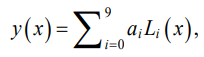
We denote the approximating line of the blade profile using function y(x). The expression of this line in the case of a number of Legendre polynomials of the ninth degree is represented as:
 (1)
(1)
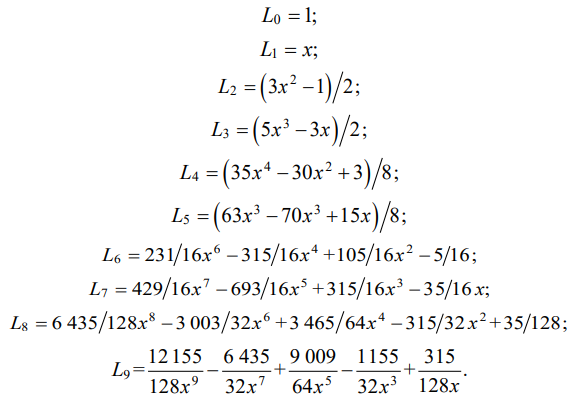
where ai — coefficients that are parameters of the model; Li(x) — Legendre polynomials calculated by formulas:
 (2)
(2)
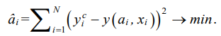
Let the coordinates of the initial blade profile be given by a set of points 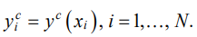 Substituting values xi in functions (2), we obtain matrix X of size N × 10. The coefficients of the approximating polynomial for the given blade profiles were found by the least squares method from the minimum condition of the sum of squared deviations of the given values
  and calculated through the regression equation (1):
 (3)
(3)
The estimates of coefficients  were calculated using the well-known regression analysis formula:
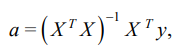 (4)
(4)
where a — notation for the vector of coefficient estimates; y — for the vector of points of given profile
The approximation accuracy was estimated by the determinacy coefficient of the model (the coefficient of determination R2), which, with a good approximation, should be close to unity:
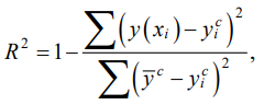 (5)
(5)
where  — average value of
In design practice, it is customary to describe the leading and trailing edges of the contour of the blades with the radii of circles. In this regard, the coordinates of the points of the approximated profiles between the arcs of the circles of the leading and trailing edges were considered in this paper. For the purposes of approximation, the contour of the blade in question was assumed to be horizontal, so that the blade chord line coincided with the abscissa axis of the Cartesian coordinate system. To preserve the orthogonality condition of the models, size normalization is mandatory. In this regard, all dimensions were normalized by the length of the blade chord, so that the abscissas of the profile points lay in the range of 0.1. This provided the orthogonality of functions (2) with coefficients calculated by formulas (4).
Research Results. Table 1 shows the coefficients of approximating polynomials for blade profiles belonging to different types of GTE to study the heat fatigue of a thermal-protective coating consisting of two metal and ceramic layers: profile of the compressor blade C8626 [13], profile of the NASA blade of a highly efficient high-pressure GTE [18], and profile of the simulator blade used in [19].
Table 1
Coefficients of approximating polynomials for blade profiles from different sources
Coefficients | [13] | [18] | [19] | |||
suction side | pressure side | suction side | pressure side | suction side | pressure side | |
142.4250 | –123.0993 | –1275.6471 | 717.8336 | –1043.6707 | 527.0915 | |
–374.3446 | 324.9875 | 3328.6126 | –1868.9670 | 2719.5055 | –1369.9895 | |
477.9332 | –417.7186 | –4181.1239 | 2338.1048 | –3406.1466 | 1707.9198 | |
–444.4554 | 392.7204 | 3794.0526 | –2108.4202 | 3077.0694 | –1531.8025 | |
324.6819 | –292.0489 | –2684.7257 | 1479.0172 | –2164.2992 | 1066.1471 | |
–189.2284 | 174.3673 | 1502.4170 | –818.4219 | 1201.7203 | –583.7501 | |
86.8260 | –82.4103 | –654.4877 | 351.5869 | –518.2516 | 247.3087 | |
–30.0775 | 29.5457 | 211.8930 | –111.9355 | 165.6344 | –77.2958 | |
7.1533 | –7.3024 | –46.0284 | 23.8450 | –35.3931 | 16.0493 | |
–0.9024 | 0.9652 | 5.1021 | –2.5861 | 3.8411 | –1.6752 | |
0.9999 | 0.9993 | 0.9896 | 0.9990 | 0.9982 | 0.9994 | |
Figure 1 shows the starting points of these profiles and the corresponding approximating lines.
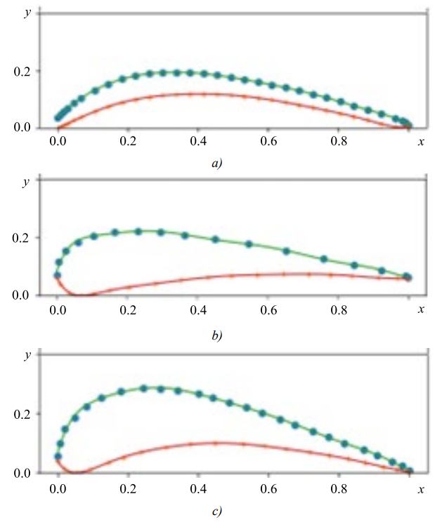
Fig. 1. Initial points and approximating lines of blade profiles presented in Table 1, sources of blade profiles: a — [13]; b — [18]; c — [19]
As mentioned above, the aim of parameterization in this paper is to approximate the profile by a continuous function followed by modeling the distribution of external parameters over the surface of the blade. To illustrate the possibility of solving this problem, we consider a simple two-dimensional model of a blade in a stationary aerodynamic flow, in the approximation of potential flow. In this case, the distribution of the velocities of flow v(x, y) is described by the equation:
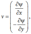 (6)
(6)
where function ψ is found from the solution to the Laplace equation:
 (7)
(7)
which in this case corresponds to the incompressibility condition (∇ ∙ v = 0) and vortex-free flow (∇ × v = 0).
The boundary condition for function ψ will be equal-zero velocity in the normal direction of the blade surface, which means that ψ is constant on this surface.
We denote the profile line of the blade surface by S and search for a solution to equation (7) in region Ω, bounded by the outer part with respect to S and the inner part with respect to circle C of a sufficiently large diameter, compared to the length of the blade chord, so that the flow is homogeneous on surface C. That is, the conditions are set at the boundary of the domain 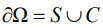 :
:
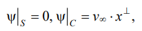 (8)
(8)
where  — uniform flow velocity vector.
After calculating the velocities, the pressure distribution can be found using the Bernoulli equation:
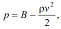 (9)
(9)
where ρ — gas density; B — Bernoulli's constant, which can be set equal to  where
where  — pressure at an infinite distance from the blade.
The variational formulation of problem (7) looks like this:
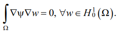 (10)
(10)
The solution to this problem was carried out by the finite element method. For comparison, the calculation was performed for three variants of blade profiles, shown in Table 1, with the same chord length .
The obtained results were further used in solving the problem of cooling the blade in an aerodynamic flow. Such a task makes sense for thermocyclic testing of coatings on simulator blades. In this case, the problem statement looked as follows:
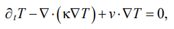 (11)
(11)
where T — temperature; t — time; κ — thermal diffusivity coefficient.
Initial temperature distribution:
 (12)
(12)
was assumed to be as follows: inside the blade, a constant temperature was 400°С, ambient temperature was 0°С. The boundary conditions corresponded to the absence of heat flow on the outer contour C:
 (13)
(13)
The distribution of flow velocities in problem (11) was calculated when solving problem (10), while the velocity on contour C was assumed to be (length dimension in units of chord length). The thermal conductivity coefficients of the blade and gas were assumed to be 0.1 and 0.01 respectively.
The program code for solving problems (10), (11) was written in the input language of the universal finite element package FreeFem++ [20].
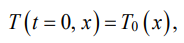
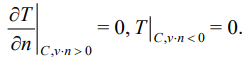
Figure 2 shows the pressure and temperature distributions calculated as a result of solving problems (11), (12), when the blade cools down for 25 seconds in the aerodynamic flow for the three studied blade profiles shown in Figure 1. Table 2 shows the calculated values of the minimum relative pressures near the blade surfaces and the maximum temperatures of the blades.
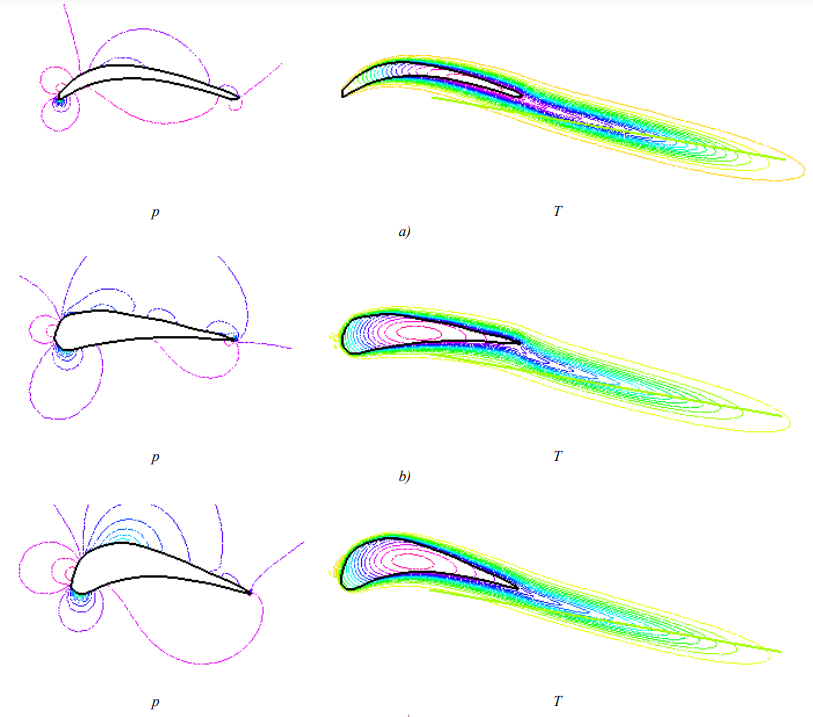
Fig. 2. Calculated distributions of pressure (p, left) and temperature (T, right) when modeling the flow and cooling in the flow of the blades of the studied profiles (profile designations — as in Fig. 1). Flow vector direction angle with blade chord direction was 10о
Table 2
Minimum relative pressure near the surface of the blade and maximum temperature of the blade after 25 s cooling in the aerodynamic flow
Parameters | Blade profile | ||
[13] | [18] | [19] | |
 | 0.599 | 0.699 | 0.720 |
 | 156.9 | 245.2 | 263.4 |
Discussion and Conclusion. Judging by the data presented in Table 1, the coefficients of determination for all studied blade profiles were close to unity, despite the fact that the shapes of the profiles differed significantly. This confirms the good quality of the approximation and is also illustrated by the data in Figure 1. Thus, the proposed method makes it possible to construct approximating blade profile lines for various types of GTE with high accuracy.
The paper also illustrates the possibility of using approximating functions under calculating the distribution of pressures and temperatures on the surface of the blade on the basis of solution to the problem of gas dynamics. Further, this distribution can be used to optimize the structure of special blade coatings, such as heat-protective coatings. The data shown in Figure 2 and in Table 2, confirm that this task can also be successfully solved. The patterns of pressure and temperature distributions for different blade profiles have common features, but the detailed picture differs. It can be seen, specifically, that the blade of the profile [19], which has a larger cross-sectional area compared to the others, is characterized by a higher value of relative pressure in the area of the outlet edge and a lower cooling rate. This is also illustrated by the data given in Table 2. Since, from the point of view of the strength of the adhesive bond of the coating with the substrate, the most dangerous forces are directed normally away from the surface of the blade, the relative minimum pressure near the surface is relevant. Its values are presented in Table 2. With account to the calculation obtained, it is possible to reasonably approach the design of a special coating for the surface of a blade of a specific profile: adjust the materials and thickness of the coating depending on the degree of loading of individual surface areas.
Note that these calculation results are presented only as an illustration of the possibilities of the proposed profile approximation technique. Therefore, the model of gas dynamics used in the work is quite simplified. In a specific task, it is necessary to use a more rigorous model with parameters corresponding to the specified type and mode of the GTE operation.
Thus, the proposed technique for approximating the blade profile of the GTE, based on the use of orthogonal polynomials, is a convenient tool that provides automating the development of a geometric model of the blade and comparing different types and profiles of blades, solving the corresponding problems of gas dynamics. At the same time, for a given blade profile and working conditions of a GTE, it is possible to obtain a distribution of temperatures and forces acting on the blade surface, which is required to predict the durability of special coatings [21]. Based on this calculation, it is possible to optimize the coating technology by varying its thickness and/or composition, increasing the coefficient of durability in the most dangerous areas.
1. Krymov VV, Eliseev YuS, Zudin KI. Production of Gas Turbine Engine Blades. Moscow: Mashinostroenie; 2002. 376 p. (In Russ.).
2. Pankov VP, Babayan AL, Kulikov MV, Kossoy VA, Varlamov BS. Heat-Protective Coatings for Turbine Blades of Aircraft Gas Turbine Engines. Polzunovskiy Vestnik. 2021;1:161–172.
3. Nirmith Kumar Mishra, Shyam Raja Puppala, Laxmi Teja Kolanu, Jyoshnavi Amudapuram, Ratan Makthal. Design and Analysis of a Gas Turbine Blade. AIP Conference. Proceedings. 2023;2492(1):020040. https://doi.org/10.1063/5.0113346
4. Cohen H, Rogers GFC, Straznicky P, Saravanamuttoo HIH, Nix A. Gas Turbine Theory, 7th Ed. London: Pearson; 2017. 606 p.
5. Jabbar A, Rai AK, Reddy PR, Dakhil MH. Design and Analysis of Gas Turbine Rotor Blade Using Finite Element Method. International Journal of Mechanical and Production Engineering Research and Development. 2014;4(1): 91–112.
6. Win Lai Htwe, Htay Htay Win, Nyein Aye San. Design and Thermal Analysis of Gas Turbine Blade. International Journal of Mechanical and Production Engineering. 2015;3(7):62–66. URL: https://www.iraj.in/journal/journal_file/journal_pdf/2-165-143653913462-66.pdf (accessed: 14.12.2023).
7. Leloudas SN, Eskantar AI, Lygidakis GN, Nikolos LK. Low Reynolds Airfoil Family for Small Horizontal Axis Wind Turbines Based on RG15 Airfoil. SN Applied Sciences. 2020;2:371. https://doi.org/10.1007/s42452-020-2161-1
8. Eftekhari S, Al-Obaidi ASM. Investigation of a NACA0012 Finite Wing Aerodynamics at Low Reynold’s Numbers and 0° to 90° Angle of Attack. Journal of Aerospace Technology and Management. 2019;11(1):e1519. URL: https://www.scielo.br/j/jatm/a/JdnMCtH6R3PhTBZ69YNqNfd/?format=pdf&lang=en (accessed: 14.12.2023).
9. Pritchard LJ. An Eleven Parameter Axial Turbine Airfoil Geometry Model. In: Proc. ASME International Gas Turbine Conference and Exhibition. Vol. 1: Aircraft Engine; Marine; Turbomachinery; Microturbines and Small Turbomachinery. New York: ASME; 1985. https://doi.org/10.1115/85-GT-219
10. Mengistu T, Ghaly W, Mansour T. Aerodynamic Shape Optimization of Turbine Blades Using a Design-Parameter-Based Shape Representation. In: Proc. ASME Turbo Expo 2007: Power for Land, Sea, and Air. Vol. 6: Turbo Expo 2007, Parts A and B. New York: ASME; 2007. https://doi.org/10.1115/GT2007-28041
11. Vinogradov LV, Alekseev AP, Kostjukov AV. Turbine Blade Profile of Curves Bezier. RUDN Journal of Engineering Research. 2013;(3):10–15.
12. Vinogradov LV, Mamaev VK, Oschepkov PP. CAD of Turbine Profile Type A3K7 NACA by the Method of Nonlinear Transformation. RUDN Journal of Engineering Research. 2017;18(3):299–307.
13. Mamaev VK, Vinogradov LV, Oschepkov PP. Modeling the Set of Blade Profiles of a Gas Turbine Engine. RUDN Journal of Engineering Research. 2019;20(2):140–146. https://doi.org/10.22363/2312-8143-2019-20-2-140-146
14. Shabliy L, Kolmakova D, Krivtsov A. Parametric Modeling of Blade Machines during Optimization. Izvestia RAS SamSC. 2013;15(6–4):1013–1018.
15. Blinov VL, Brodov YuM, Sedunin VA, Komarov OV. Parametric Profiling of 2D Compressor Rows for Multicriteria Optimization Task. Power Engineering: Research, Equipment, Technology. 2015;(3–4):86–95.
16. Schnoes M, Nicke E. Exploring a Database of Optimal Airfoils for Axial Compressor Design. ISABE. 2017;21493:1–17.
17. Beals R, Wong R. Special Functions and Orthogonal Polynomials. Cambridge: Cambridge University Press; 2016. 473p. https://doi.org/10.1017/CBO9781316227381
18. Timko LP. Energy Efficient Engine High Pressure Turbine Component Test Performance Report. Washington, DC: NASA; 1984. 173 p.
19. Tikhomirova EA, Budinovskiy SA, Zhivushkin AA, Sidokhin EF. Features of Thermal Fatigue Development in Detail, Produced from Heat-Resistant Alloys with Coatings. Aviation Materials and Technologies. 2017;48(3):20–25.
20. Hecht F. FreeFEM Documentation. Release 4.6. Paris: Sorbonne University; 2021. 673 p.
21. Soloviev ME, Raukhvarger AB, Baldaev SL, Baldaev LKh. Kinetic Model of Destruction of Adhesive Bounding of Power Coating and Metal Host Material. Science Intensive Technologies in Mechanical Engineering. 2023;139(1):9–19. https://doi.org/10.30987/2223-4608-2023-1-9-19
Mikhail E. Soloviev, Dr.Sci. (Phys.-Math.), Professor of the Department of Information Systems and Technologies
88, Moskovsky Ave., Yaroslavl, 150023
Yulia N. Shuleva, Teaching Assistant of the Department of Information Systems and Technologies
88, Moskovsky Ave., Yaroslavl, 150023
Sergey L. Baldaev, Сand.Sci. (Eng.), Deputy General Director for Technology
9A, Yuzhnaya St., Scherbinka, Moscow
Lev Kh. Baldaev, Dr.Sci. (Eng.), General Director
9A, Yuzhnaya St., Scherbinka, Moscow
Soloviev M.E., Shuleva Yu.N., Baldaev S.L., Baldaev L.Kh. Approximation of the Profile of Gas Turbine Engine Blades. Advanced Engineering Research (Rostov-on-Don). 2024;24(1):78-87. https://doi.org/10.23947/2687-1653-2024-24-1-78-87. EDN: QOELMG


Advanced Engineering Research (Rostov-on-Don)
ISSN 2687-1653 (Online)
Contact with: Publisher / Editorial Office of the Journal
Publisher: Don State Technical University - DSTU, Rostov-on-Don, Russia - https://donstu.ru/en/
Editor-in-Chief: Alexey N. Beskopylny, Dr.Sci. (Eng.), Professor, Vice-Rector, Don State Technical University (Rostov-on-Don, Russia)
Don State Technical University
1, Gagarin Sq., Rostov-on-Don, 344003, Russia
tel.: +7 (863) 2738-372, e-mail: vestnik@donstu.ru
16+
Processing of personal data


