


Contents
Scroll to:
https://doi.org/10.23947/2687-1653-2024-24-2-198-206
EDN: FPQRSJ
Scroll to:
Introduction. Safety of navigation and development of underwater mineral deposits require the accurate detection of various underwater objects. The literature discusses the issues of tracking their motion and trajectory. Sonar methods are proposed to maintain high accuracy of underwater object positioning. High accuracy of the bearing of stereo sensors with an ultrashort base is noted. However, this equipment is sensitive to the sampling rate of the signals, which causes “sampling noise”. There are no publicly available publications dedicated to the solution to this problem. The presented study is designed to fill this gap. This work is aimed to study the possibility of obtaining data clarifying information about the bearing of underwater objects through using the phase information about echoed probing signals and an additional procedure for resampling the source data.
Materials and Methods. The location of the object was determined using the experimental complex for studying hydroacoustic sensors created by V.A. Shirokov and V.N. Milich at the Udmurt Federal Research Center, the Ural Branch of the Russian Academy of Sciences. A stereo sensor with a small base (30 mm) was used compared to the distance to the object (≈800–900 mm). Digital filtering methods and mathematical apparatus of correlation analysis of return hydroacoustic signals obtained by the phase method were used for data processing.
Results. The results of comparing two methods for determining the bearing on an object are presented: by the difference in the time of arrival of the pulse-leading edges and by the maximum of the cross-correlation function (CCF). The change in bearing as the object moves, is graphically shown. The use of the leading edge of the signal caused small outliers of values along the entire bearing curve (less than 0.12 rad). At the maximum CCF, emissions were recorded only in some areas, but they were quite significant (about 0.17 rad). It showed how to select points corresponding to a smoother and more valid object trajectory, and how to work with erroneous points. The presented method of error correction can be implemented programmatically. With a quasi-harmonious signal, rare measurements of the original signal are interpolated by frequent calculated values. Thanks to this virtual increase in the sampling rate (oversampling), intermediate indicators can be recorded in the digitized source data. Interpolation of the signal values by a cubic spline allowed us to obtain 20 points for 1 period of the signal instead of 5 points in the original version. In this case, the trajectory formed with the maximum CCF is more correct.
Discussion and Conclusion. The direction-finding problem can be solved with the accuracy required for practical application. Taking into account the factor of smoothness and continuity of the object's trajectory makes it possible to qualitatively correct the selection of the maximum of the cross-correlation function of the stereo sensor signals. The proposed methods have great potential for the development of underwater vision systems.
Shirokov V.A., Bazhenova A.I., Milich V.N. Features of Bearing on Underwater Object Using Phase Information of a Differential Stereo Sensor. Advanced Engineering Research (Rostov-on-Don). 2024;24(2):198-206. https://doi.org/10.23947/2687-1653-2024-24-2-198-206. EDN: FPQRSJ
Introduction. Safety of navigation and work in underwater mineral deposits require high-quality detection of underwater objects and tracking their movements [1]. Hydroacoustic sensors are used in underwater surveillance systems. They capture the signal reflected from the object and provide for the calculation of its location using the trilateration method [2]. In this process, each sensor provides information about the time interval of the probing signal reflected from the object. In the case of using several sensors [3], it becomes possible to solve the problem of spatial resection and determine the coordinates of the observed object [4]. To increase the accuracy of measurements, it seems promising to use stereo sensors with an ultrashort base as a receiver [5], which allow obtaining phase information [6] and determining the bearing on an object [7]. The possibilities of using sonar data on remote underwater targets, as well as on the bearing of underwater objects [8] through the use of phase [9] or frequency [10] information of reflected probing signals have been studied.
At the same time, it is known that the signal sampling procedure causes errors in determining the parameters of the trajectory of underwater objects [11]. This applies to both distance measurements and bearing determination procedures. Digitization of the analog sensor signal, which is required for further digital processing, introduces the so-called “sampling error”. The error caused by the signal amplitude quantization is estimated by the number of quantization levels of the analog-to-digital converter. The error caused by time sampling is proportional to the range of the quantization time interval and the stress rate. Therefore, the sampling frequency of the signal is sought to be as high as possible above the upper frequency of the signal itself. However, increasing the sampling rate in a number of cases is limited by the capabilities of recording equipment: processor, analog-to-digital converter, data transmission channels, data storage devices. The limited possibilities of sampling in time when performing trajectory measurements do not allow for accurate recording of the extreme values of the trajectory (range and bearing). As a result, the accuracy of measurement results decreases, and outliers appear on the fixed trajectories. To eliminate this disadvantage, it is necessary to study the potential of oversampling the digitized sonar signal. There are no publicly available publications dedicated to solving this problem. The materials of this article fill in the existing gap.
The objective of the presented study is to evaluate the possibilities of determining the bearing on an object using phase information, and to develop a phase method of bearing using the resampling of a digitized sonar signal.
Materials and Methods. An algorithm for determining coordinates using the direction-finding phase method is considered. The results of its testing for an object moving along a circular trajectory in an experimental pool are presented.
Setting up an experiment. During the experiments, an experimental assembly created by V.A. Shirokov and V.N. Milich at the Udmurt Federal Research Center of the Ural Branch of the RAS was used to determine the location of an object in the hydroenvironment with the direction finding by the phase method [12]. This is a laboratory measuring complex with a linear aqua medium in the form of an extended cylindrical tank (hydro waveguide) and a basin equipped with a system for generating test sonar signals. The installation elements used in the experiments are described in detail below.
1. Hydroacoustic signal emitter with known coordinates S (Fig. 1). An amplitude-modulated signal is used in the work [13].
2. Reflecting object. In the experiment, an extended cylindrical object is used as a test object — a copper wire whose diameter (0.15 mm) is significantly less than the acoustic wave length (1.5 mm). In the presented work, the problem is solved on a plane; therefore, for the compilation of computational procedures for calculating coordinates, this object can be considered a point.
3. Stereo sensor that converts a sonar signal into an electrical one. The coordinates of each of the two receivers of the stereo sensor are known (see st1, st2 in Fig. 1).
4. Hardware-softwarecomplex that performsamplification,digitizationandprocessing of sensorsignals.
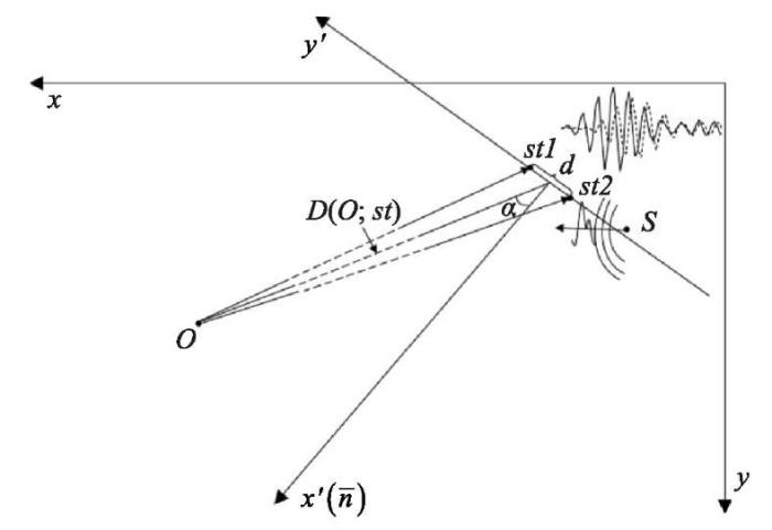
Fig. 1. Location of the receiving sensors (stereo sensor with two receivers st1 and st2) and emitter (S) in the plane of experimental tank (xy). Here, d — stereo sensor base; D(O; st) — distance between the stereo sensor and the object; α — bearing on the object; plate (x’y’) is formed by the plane of the stereo sensor and normal n to it
The measurement result is a recording file of the received two-channel signal.
Algorithm for processing measurement results. Using a stereo sensor with a small base (30 mm) compared to the distance to the object (≈ 800–900 mm) allows us to apply simplified formulas.
Now then, we calculate the coordinates of the object under study in the system x'y', formed by the plane of the stereo sensor and the normal to it. To do this, we use the algorithm that includes five stages.
1. Preprocessing:
High-frequency filtering is used in the work.
2. Selecting informative fragments imp1, imp2 (in two channels) containing pulses reflected from the object under study. To do this, thresholding is performed according to amplitude A of the signal. The threshold is assumed to be equal to p×max(A) (p = 0.5).
This processing allows for determining the leading edge of the pulse (BeginIndex), reflected from the object. Sections [BeginIndex–0.5×LenSignal; BeginIndex+LenSignal] are cut from two signal channels. Here, LenSignal — length of the input signal. As a result, we get two signals imp1 and imp2 with a length of 1.5×LenSignal. Each of them contains the pulse reflected from the object.
3. Calculation of distanceD(O; st) between the object and the stereo sensor.
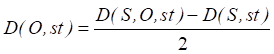 . (1)
. (1)
4. Determination of bearing α on object [14]:
 (2)
(2)
where λ — wavelength; F — signal frequency; dt — sampling interval; m — difference in the arrival of the reflected pulse to two stereo sensors (in counts); d — base of the stereo sensor (in the presented study λ = 1.5 mm, F = 1 MHz, dt = 0.2 µs, d = 30 mm).
5. Calculation of the coordinates of the analyzedobjectin the systemformed by the plane of the stereosensoranditsnormal(Fig.1),according to the formulas: x’= D(O, st) ×cos(α); y’= D(O, st) ×sin(α).
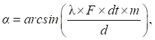
Determining the bearing on an object. Assume the condition of the smallness of the stereo base compared to the distance from the sensor to the object. In this case, the stereo sensor allows us to determine the bearing on the object using information about the phase difference of the received pulses previously reflected from the object, as well as the difference in the time of arrival of the leading edges of the pulses received by the stereo sensor (Fig. 2).
Fig. 2. Determination of difference in the moments of arrival of stereo signals ds, which are indicated by solid imp1(t) and dotted imp2(t) lines. Th1, Th2 — thresholds for the first and second stereo pair signals, respectively; dt — sampling interval; А — signal value in volts; t — time
To implement this approach, the following procedures are performed.
1. Identification of the moments of arrival of the leading edges of stereo signals using thresholding [15] with threshold p×max(A). In this paper, coefficient p is assumed to be 0.5 [16].
2. Calculation of difference ds (number of intervals dt) between the leading edges of the pulses registered in two receivers of the stereo sensor.
3. Calculation of bearing α by formula (1). We take value d for
With this method of calculating the phase shift, the leading edge of the signal is the main indicator of the pulse reflected from the object. The internal structure of the signal is not taken into account, which may be crucial for the correct determination of the bearing on the object. We take into account the similarity of the received signals and consider another approach to calculating the bearing — based on the cross-correlation function (CCF) of stereo signals. It is logical to determine the phase shift by the CCF maximum. The elements of the bearing calculation algorithm using CCF are described below.
1. Calculation of the CCF pulses arrived at two receivers of one stereo sensor: r= xcorr(imp1, imp2). The value of function xcorr at the shift of m of the second signal relative to the first is calculated as follows:
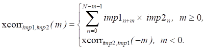
Here, N — length imp1 and imp2, –N<m<N.
2. Determination of the maximum CCF and the corresponding shift dc (in counts).
3. Calculation of bearing α from formula (1) taking into account that value dc is taken as m.
Research Results
Testing the bearing determination methods. The presented methods for determining the bearing on an object (by the difference in the time of arrival of the pulse-leading edges and by the CCF maximum) were tested for an object moving along a circular trajectory in the experimental pool. A harmonic signal with a duration of 7 periods and a frequency of 1 MHz was used. Digitized stereo signals were recorded at 256 points of the object's trajectory. The digitization frequency was 5 MHz.
Figure 3 shows the change in bearing values as the object moves around the circle for the two proposed approaches (difference of the leading edges, CCF maximum).
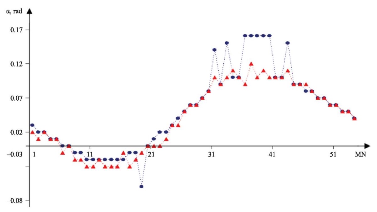
Fig. 3. Deviation of bearing α on the object making a circular motion. Indicators were obtained using two approaches (red marker — difference in the time of arrival of the leading edges of stereo signals, blue marker — CCF maximum). MN — measurement number, α — bearing on the object
When using the signal-leading edge (Fig. 3, red marker), small outliers of values are observed almost along the entire curve of the bearing on the object. When using the CCF maximum (Fig. 3, blue marker), only in some areas there are outliers of bearing values, but they are quite large. Perhaps this is due to the peculiarities of the object's movement in the area where the probing and reflected signals cross the zone of turbulence caused by the object's movement. When finding the phase shift of stereo signals using the CCF maximum, additional errors occur, which is then reflected in the calculated trajectory of the object. Also, outliers in the calculated bearing values may be due to an insufficiently high sampling rate. The values of these errors are significantly higher than the emission values observed for the method using the pulse-leading edge.
Figure 4 a presents the trajectories of the object, calculated using the global CCF maximum and its neighboring local maxima.
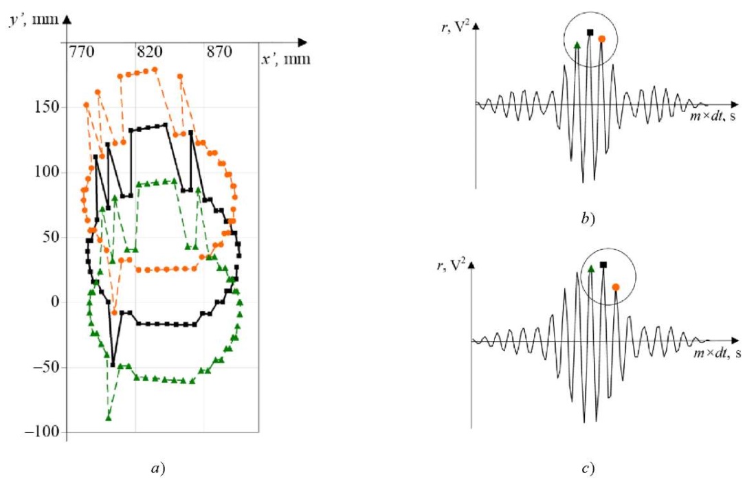
Fig. 4. Analysis of the trajectories of the circular motion of the object: a — trajectories calculated using the global CCF maximum (black marker), local nearest right CCF maximum (orange marker), local nearest left CCF maximum (green marker); b — example of CCF, whose global maximum corresponds to the correct value of the coordinates of the object; c — example of CCF, in which the left local CCF maximum corresponds to the correct value of the coordinates of the object
Using aprior information about the smoothness of the movement of the experimental object, it is possible to select points that correspond to a smoother and more valid trajectory. This approach is used in other works [17]. In Figure 4 a, at x’ϵ[ 800;870], y’>0, the correct values are on the curve for the trajectory calculated from the left local CCF maximum. There are also erroneous points. If they are replaced by the points of the trajectory obtained as a result of using the right local CCF maximum, the correct value of the trajectory point can be calculated (x’≈800, y’<0 in Fig. 4 а). This graphical method of error correction can be implemented programmatically.
Thus, at some points of the trajectory, the correct phase shift of the stereo signals required for calculating the bearing may correspond not to the global CCF maximum, but to one of the neighboring local extremes (Fig. 4 b, c). This shift of the CCF maxima may be due to an insufficiently high sampling rate of the signals. This also explains the stepwise nature of the resulting trajectory.
Taking into account the quasi-harmonicity of the signal, it is proposed to use interpolation of rare measurements of the original signal with frequent calculated values. This virtual increase in the sampling rate (oversampling) makes it possible to fix intermediate values in the digitized source data. Interpolation of the signal values by a cubic spline allowed us to obtain 20 points for 1 period of the signal instead of 5 points in the original version. Figure 5 shows the calculated trajectories of the object, formed with preliminary resampling of the signals.
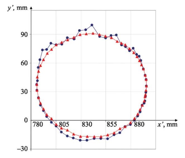
Fig. 5. Calculated object motion trajectories obtained for stereo signals with a virtually increased sampling rate: blue marker — difference in the time of arrival of the signal-leading edges is used; red marker — CCF maximum is used
The red line is the object’s trajectory, obtained using the CCF maximum to calculate the bearing from pre-interpolated data. It seems to be more correct compared to a similar trajectory obtained using the difference in the leading edges of reflected pulses (blue line).
Discussion and Conclusion. Analysis of the features of determining the bearing on an underwater object using the mutual phase information of the differential stereo sensor signals makes it possible to draw the following conclusions.
Thus, the investigated possibilities of refining the phase direction finding method (resampling of digitized signals and using the CCF maximum) make it possible to effectively assess the trajectory of an underwater object.
The conditions for obtaining a smooth correct trajectory of the tracked object are described. The oversampling of interpolated quasi-harmonic stereo signals digitized with insufficient sampling rate serves this goal. At the same time, the bearing calculation method is used with the maximum of the cross-correlation function of the stereo sensor signals.
The data in Figure 5 confirm that the direction-finding problem can be solved with the accuracy required for practical application. Taking into account the factor of smoothness and continuity of the object's trajectory allows for the unique adjustment of the selection of the maximum of the cross-correlation function of the stereo sensor signals (Fig. 4).
The proposed methods are of great importance for the development of underwater vision systems.
1. Meng Joo Er, Jie Chen, Yani Zhang, Wenxiao Gao. Research Challenges, Recent Advances, and Popular Datasets in Deep Learning-Based Underwater Marine Object Detection: A Review. Sensors. 2023;23(4):1990. https://doi.org/10.3390/s23041990
2. Andreev MYa, Ochrimenko SN, Parshukov VN, Rubanov IL, Kozlovsky SV, Illarionov AA. Bistatic System for Searching Underwater Objects (Bistatic Hydrolocator). Sensors & Systems. 2019;233(2):50–56.
3. Matveeva IV, Shejnman EL. Determination of Current Target Coordinates in Bistatic Echo Ranging Mode at Uncertainty of Bearing Estimation. Hydroacoustics. 2017;31(3):9–12.
4. Matveeva IV, Sheinman EL, Shkol’nikov IS. Efficiency of Determination of Coordinates and Motion of Sea Objects at Bistatic Location of Moving Observing Systems. Hydroacoustics. 2016;26(2):28–32.
5. Arsent’ev V, Krivolapov G. Positioning of Objects in Hydroacoustic Navigation System with Ultrashort Base. The Herald of the Siberian State University of Telecommunications and Information Science. 2018;(4):66–75.
6. Matvienko YuV, Khvorostov YuA, Kuleshov VP. Peculiarities of Application of Scalar-Vector Sound Receivers in Systems for Control of Underwear Situation in Local Areas. Underwater Investigations and Robotics. 2022;42(4):4–15. https://doi.org/10.37102/1992-4429_2022_42_04_01
7. Terrachiano DS, Costanzi R, Manzari V, Stifani M, Caiti A. Passive Bearing Estimation Using a 2-D Acoustic Vector Sensor Mounted on a Hybrid Autonomous Underwater Vehicle. IEEE Journal of Oceanic Engineering. 2022;47(3):799–814. https://doi.org/10.1109/JOE.2021.3132647
8. Yanhou Zhang, Chao Wang, Qi Zhang, Lianglong Da, Zhaozhen Jiang. Bearing-only Motion Analysis of Target Based on Low-Quality Bearing-Time Recordings Map. IET Radar, Sonar & Navigation. 2024;18(5):765–781. https://doi.org/10.1049/rsn2.12519
9. Profatilova GA, Soloviev GN. Low Elevation Measurements Using Phase Method in the Presence of Interference. Herald of the Bauman Moscow State Technical University. Series Instrument Engineering. 2013;90(1):3–12.
10. Kaevitser VI, Krivtsov AP, Smolyaninov IV, Elbakidze AV. Frequency Method for Measuring the Angular Coordinates of an Underwater Vehicle by a Hydroacoustic System of Local Positioning. Journal of Radio Electronics. 2021;3:11. https://doi.org/10.30898/1684-1719.2021.3.1
11. Arsent’ev V, Krivolapov G. On the Characteristics of Phase Direction Finder of the Hydroacoustic System Drive for Delivering Autonomous Uninhabited Underwater Vehicle. The Herald of the Siberian State University of Telecommunications and Information Science. 2021;53(1):23–35. https://doi.org/10.55648/1998-6920-2021-15-1-23-35
12. Shirokov VA, Milich VN. Experimental Complex for Studying the Possibilities of Using Hydroacoustic Sensors in Underwater Vision Systems. Vestnik IzhGTU named after M.T. Kalashnikov. 2021;24(4):54–64. https://doi.org/10.22213/2413-1172-2021-4-54-64
13. Arsent’ev V, Krivolapov G. Hydroacoustic Phase Direction Finder with Amplitude-Modulated Navigation Signal. The Herald of the Siberian State University of Telecommunications and Information Science. 2021;54(2):14–26. https://doi.org/10.55648/1998-6920-2021-15-2-14-26
14. Matvienko YuV. Estimation of the Practically Attainable Accuracy of Modern Ultrashort Baseline Hydroacoustic Navigation Systems for Underwater Robots. Gyroscopy and Navigation. 2023;14(2):166.
15. Egorov SB, Gorbachev RI. Determination of Level and Time Thresholds for Detectors with Normalized Indicator Process. Marine Intellectual Technologies. 2020;2(2):144–147. https://doi.org/10.37220/MIT.2020.48.2.056
16. Abraham DA. Underwater Acoustic Signal Processing. Modeling, Detection, and Estimation. Cham: Springer; 2019. P. 457–619. https://doi.org/10.1007/978-3-319-92983-5
17. Denisov VP, Dubinin DV, Krutikov MV, Mescheryakov AA. Algorithm of Abnormal Direction Errors Rejecting for Phase Finder. Proceedings of TUSUR University. 2012;26(2):36–42.
Vladimir A. Shirokov, Cand.Sci. (Eng.), Senior Researcher
34, T. Baramzina Str., Izhevsk, 426067
Aigul I. Bazhenova, Cand.Sci. (Eng.), Researcher
34, T. Baramzina Str., Izhevsk, 426067
Vladimir N. Milich, Cand.Sci. (Eng.), Leading Researcher
34, T. Baramzina Str., Izhevsk, 426067
Shirokov V.A., Bazhenova A.I., Milich V.N. Features of Bearing on Underwater Object Using Phase Information of a Differential Stereo Sensor. Advanced Engineering Research (Rostov-on-Don). 2024;24(2):198-206. https://doi.org/10.23947/2687-1653-2024-24-2-198-206. EDN: FPQRSJ

Advanced Engineering Research (Rostov-on-Don)
ISSN 2687-1653 (Online)
Contact with: Publisher / Editorial Office of the Journal
Publisher: Don State Technical University - DSTU, Rostov-on-Don, Russia - https://donstu.ru/en/
Editor-in-Chief: Alexey N. Beskopylny, Dr.Sci. (Eng.), Professor, Vice-Rector, Don State Technical University (Rostov-on-Don, Russia)
Don State Technical University
1, Gagarin Sq., Rostov-on-Don, 344003, Russia
tel.: +7 (863) 2738-372, e-mail: vestnik@donstu.ru
16+
Processing of personal data


