


Contents
Scroll to:
https://doi.org/10.23947/2687-1653-2024-24-3-238-245
EDN: EWVFBZ
Scroll to:
Introduction Violation of mutual positioning and fixation of parts worsens the operation of the equipment. Traditional approaches to solving the problem under consideration have been sufficiently studied: interchangeability of parts and the use of special equipment. Both methods involve a significant number of additional elements and assembly operations. Fixation is often provided by means of force fitting and welding. Disadvantages of these methods include assembly, residual and other stresses, engineering constraints, etc. To solve these problems, alloys with thermoelastic phase transformations are used, which provide shape memory effects (SME) to manifest themselves. This article describes, for the first time, self-positioning and self-fixation using the example of parts specially made from an alloy with SME. Materials and Methods. The pin element under pressing mandrels the blind hole of the cup and enters the seat. The alloy with SME was Ti-55.7wt%Ni. The temperature of the onset of its austenitic transformation was As = 95°C ± 5°C. The elemental composition was determined by a Shimadzu EDX-8000 X-ray fluorescence spectrometer, the phase composition — by a Shimadzu XRD-7000 diffractometer. The temperature was specified through differential scanning calorimetry. The range was 20–300°C, the heating rate was 5 deg/min. A Guide T120 thermal imager and a RangeVision DIY 3D scanner with structured illumination were used. After pressing the pin into the cup at different angles, the alignment and deviations between the axes of the cup and the pin were examined. Then, the cup was heated to 110–120°C, cooled, and control measurements were taken.
Results. Values of the deflection angle after pressing were 0.2–11°. With a rigid structure and an installation angle of 0°, the pin deflected in the mounting hole by 0.2–0.5°. The axes shifted and did not intersect. The pin was not always completely pressed in. This indicated uneven deformation of the metal and different stress values around the hole. Such a unit would soon fail. The pin took the required position after heating the cup to 110–120°C (this temperature was higher than at the end of the reverse martensitic transformation). The angular deviation of the axes was noted to be 0.03–0.1°. The maximum misalignment (0.04 mm) corresponded to high positioning accuracy. Heating during the reverse martensitic transformation created internal stresses that returned the initial geometry of the cup. They also formed the forces that positioned and fixed the pin in the hole. That is, it is the parts that provide positioning and fixation (this is selfpositioning and self-fixation).
Discussion and Conclusion. For self-positioning and self-fixation of parts due to the shape memory effect, it is necessary to avoid sharp transition lines between the surfaces of parts during design, select rounded corners or fillets, and get a clean surface without burrs. Self-fixation and self-positioning reduce defects and inaccuracies during assembly. The use of certain alloys increases the profitability of equipment production.
Balaev E.Yu. On Self-Positioning and Self-Fixation of Parts Made of Alloys with Shape Memory Effect under Component Assembling. Advanced Engineering Research (Rostov-on-Don). 2024;24(3):238-245. https://doi.org/10.23947/2687-1653-2024-24-3-238-245. EDN: EWVFBZ
Introduction. Self-positioning should be understood as spatial orientation, installation and positioning of a part and elements mating with it in units and mechanisms. Self-fixation is the interface along the surfaces of structural elements with such geometric features that provide fixation of the mating parts and a given fixation force due to the shape memory effect.
The accuracy of the mutual positioning of parts determines the correctness and reliability of the mechanisms. Valid positioning can reduce the inertia of the mechanical unit, it prevents the occurrence of system backlashes not provided by the design. Failure to comply with the requirements for the mutual positioning of parts can change the operation of the products, which is unacceptable in most cases [1].
The requirements for the accuracy of assembly of units are high in all industries, specifically, in machine-tool manufacture, aircraft, and shipbuilding. For correct, tight mating of parts, the method of group interchangeability is used. Custom tooling is often used when assembling units. As a rule, it is unique for this type of assembly operation. It provides positioning accuracy during installation and meets tolerance requirements [2].
In industrial practice (notably, in construction [3] and the oil and gas industry [4]), alloys with thermoelastic phase transformations, which provide for the shape memory effect (SME), are increasingly used. The uniqueness of such alloys is in the features of phase transformations, due to which shape memory effects are manifested, as well as superelasticity (pseudoelasticity) [5].
Shape memory in alloys with thermoelastic phase transformations is used, in particular, for power drives [6]. The effect is based on return stresses that restore the shape of the part. The phenomenon corresponds to the austenitic phase state of the elements of the power drive [7]. In the oil and gas industry, coupling joints of parts are used for pipe junction [8]. The method involves restoring the shape of elements that provide the envelopment and compression of mating parts [9]. Due to the shape memory effect during assembly, it is possible to provide such processes as spatial orientation, installation, and positioning. To do this, it is advisable to use two principles mentioned above at once:
This approach allows reducing the number of assembly stages and avoiding the use of dedicated equipment (tooling) when positioning and fixing a part made of an alloy with a thermoelastic phase transformation and for the elements of the unit mating with it.
The proposed solution opens up the possibility of replacing such fixation methods as force fitting and welding. Consequently, it is possible to avoid the disadvantages of these methods: assembly, residual and other stresses. We also note the operating restrictions associated with the strength and reliability of the fixation. In addition, it is not always technically possible to perform force fitting and welding.
It is necessary to point out another advantage of parts made of alloys with thermoelastic phase transformations. Their positioning and fixation in the assembly unit allows refusing group interchangeability of parts, from fitting parts and from additional use of control units and mechanisms in the design. This simplifies the installation and manufacture of parts with high positioning accuracy and reliable fixation of parts in the assembly unit.
The presented research article, for the first time, proposes to use thermoelastic phase transformation for positioning and subsequent fixation of parts in an assembly unit. In this case, the shape memory effect of parts ensures their self-positioning and self-fixation.
The author of this article observed the phenomenon under thermoelastic transformations, when it was required to provide fixation due to the shape memory effect of teeth. In this context, the following were considered:
The research is aimed at studying the possibilities of self-positioning (spatial orientation, installation, and positioning) and self-fixation during the manifestation of the shape memory effect of alloys with thermoelastic phase transformations. It is expected to find out what accuracy is provided in this case during the design and installation of assembly units, and what conditions need to be maintained during assembly (design features, techniques, requirements for the implementation of self-positioning and self-fixation).
Materials and Methods. For the experiments, two samples were made from an alloy with a thermoelastic phase transformation. In shape, these were cups with a special blind hole and a pin element made of heat-treated (hardened) 40X steel. The cup had an opening — two conical steps with a right (lead-in) and inverted (fixing) cone. Transitions — by radius and by the line of intersection of cones. The pin element had a mandrel shape, so when pressed into the cup, a blind hole was mandrelized, and the pin element got into the seat in the cup. All surfaces were clean, without corners and burrs. This provided:
Figure 1 shows the stages of pressing a pin element into a cup made of an alloy with SME.
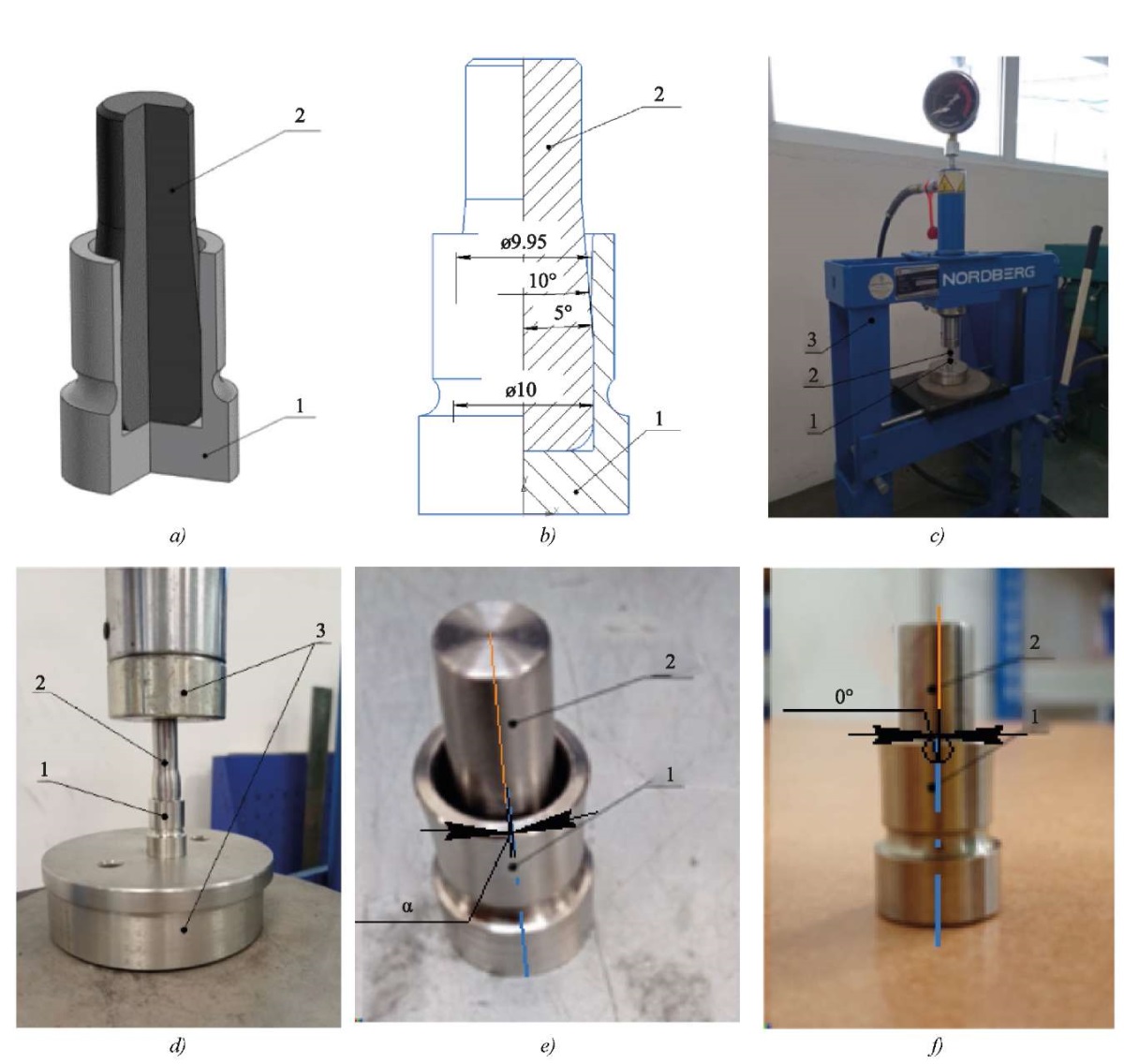
Fig. 1. Installation of pin element into seat of cup made of alloy with SME:
a — 3D model of elements assembling after installing pin element 2 into cup 1;
b — assembly drawing;
c, d — installation of pin element 2 and cup 1 in hand press 3
before pressing the pin element into cup;
e — angle between axes of symmetry α after pressing pin element 2 into cup 1
before heating (room temperature — martensitic phase of alloy);
f — pin element and cup at room temperature after heating to 110°C
(angle between axes of symmetry 0°, austenitic phase of the alloy)
Titanium nickelide Ti-55.7wt%Ni was selected as the alloy with SME. The temperature of the onset of its austenitic transformation was As = 95°C ± 5°C. Three properties listed below were determined.
This alloy allows for demonstration of the general principles of self-fixation and self-positioning of a pin element in the seat of the cup during the phase transition from martensite to austenite. At room temperature, the alloy is in the martensite phase.
A Nordberg manual press was used for pressing. The cup made of an alloy with SME was heated with a GHG 23–66 Bosch technical hot air gun. Temperature control provided uneven heating of the cup and maximum imitation of the assembling process at enterprises. Specifically, the worst installation conditions and operation with violations of the process were recreated.
The temperature and hot zones, as well as heating over the entire surface to the specified temperature, were monitored using a Guide T120 thermal imager. The positioning accuracy was determined by a stationary 3D scanner with structured illumination RangeVision DIY. Daheng cameras provided a measurement accuracy of 0.02 mm.
The sequence of operations for installing the pin element into the cup is described below.
The pin element was pressed into the cup at different angles between the axes of symmetry of the cup and the pin element. The angle sizes were from 0 to 12 degrees. The step was 3 degrees. The alignment and the angle of deviation between the axes were determined. Then the cup was heated to 110–120°C and cooled in various ways — from free cooling in air to forced cooling (by lowering into water). Then, a control measurement of the alignment and the angle of deviation between the axes was made.
Research Results. After pressing, the angle of deviation between the axes of the cup and the pin element had values in the range from 0.2° to 11° (angle α in Fig. 2 a). This indicates that with the rigidity of the structure and the installation angle of 0°, some displacement of the pin element in the mounting hole still occurs (from 0.2° to 0.5°).
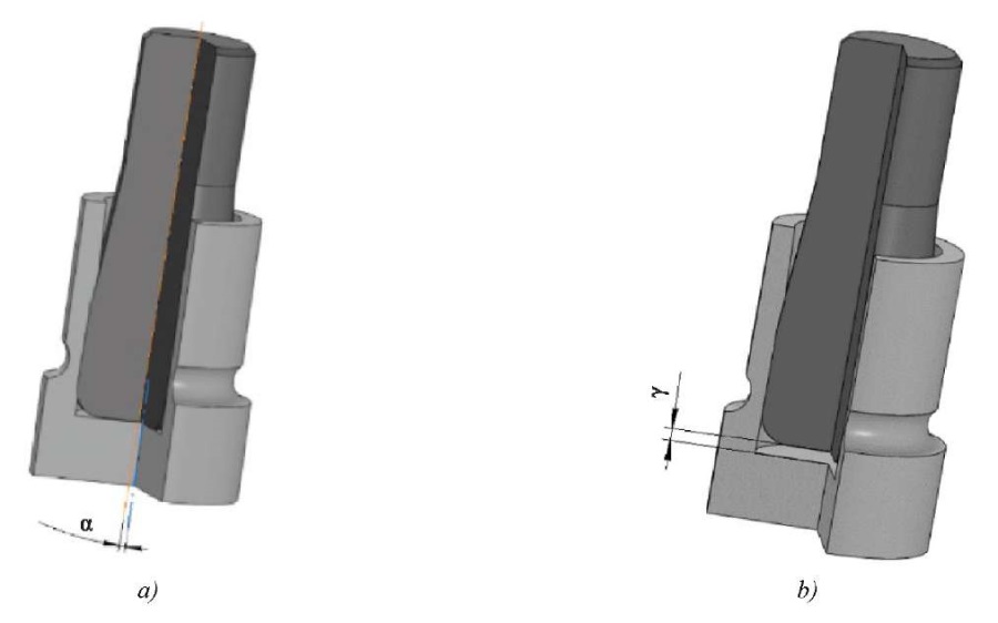
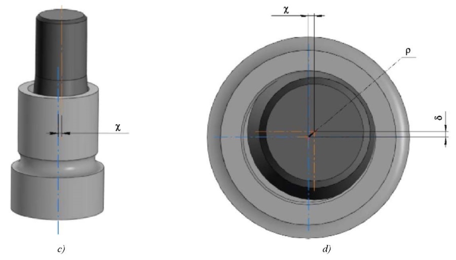
Fig. 2. Deviations arising during installation of pin element in cup mounting hole:
a — angle between the axes of symmetry;
b — displacement as a result of underpressing;
c, d — displacement of the axes of symmetry in the section plane
perpendicular to the axes of symmetry of the pin element and the cup
The axes were offset and did not have an intersection point, as shown in Figure 2 c and 2 d. If we take the axis of the cup (reference point) as the center, the offset of the axis of the pin element will be ρ = 0.2–0.8 mm (Fig. 2 d), i.e., the pin element in the cup will have an offset mounting position. In a number of cases, the pin element was not completely pressed into the cup (Fig. 2 b). Firstly, this caused uneven deformation of the metal around the hole. Secondly, it indicated that as a result of pressing, different stress values arose along the circumference of the hole. Such a unit will quickly fail when used.
The pin element occupies the required position in the cup hole and relative to the hole seat after heating the cup to 110–120°C, i.e., at a temperature higher than at the end of the reverse martensitic transformation.
The positioning accuracy of the pin element in the cup was studied using a stationary 3D scanner with structured illumination RangeVision DIY and Daheng cameras. The angular deviation of the axes was recorded in the range
of 0.03–0.1°. The maximum value of the misalignment was 0.04 mm, which corresponded to high positioning accuracy for assembly units.
It should be noted that there is a similarity between the two mechanisms that provide:
The specified shape of the part made of an alloy with shape memory effect of the cup in the austenitic state corresponds to the shape in which the pin element exactly occupies the position required by the design of the unit. At a temperature corresponding to the martensitic phase state, the mechanical characteristics of the alloy are lower than at a temperature corresponding to austenite. In this case, it is possible to specify a shape into which the pin element can be easily mounted. With such installation, the positioning of the pin element does not correspond to the required.
Subsequent heating of the glass as a result of the reverse martensitic transformation creates internal stresses that allow the original shape to be restored. They can be conventionally called return stresses. In this case:
Evidently, it is the parts that provide self-positioning and self-fixation. No special equipment or special assembly techniques are needed.
There is a process similar to the one described above. To operate the satellite antenna deployment mechanism, the power drive uses the force developed by the return stresses during the reverse martensitic transformation of the working element made of an alloy with SME.
Discussion and Conclusion. The displacement of the pin element inside the cup mounting hole is provided by design features that can be applied to all mating parts under self-positioning and self-fixation due to the shape memory effect of alloys with thermoelastic phase transformations. Techniques that allow maintaining the required design features are listed below:
These requirements should be taken into account when designing. This will provide the desired mutual displacements of parts with significantly less force. In this case, the force is compared to that given by the return stresses during the reverse martensitic transformation of the alloy with thermoelastic phase transformations (the cup is made of such material).
Self-fixation and self-positioning can maintain assembly accuracy, eliminate mounting and engineering inaccuracies during installation work, and reduce defects. The use of some alloys has economic substance, i.e., it works for the profitability of the final product [11]. These and other advantages of the approach described in the article can be implemented in machine tool manufacturing. The method seems useful for developing oil and gas, precision and other equipment with high requirements for the geometric accuracy of parts.
1. Nazaryev AV, Bochkarev PYu. Improving the Principles of Identifying Critical Requirements for the Assembly of High-Precision Products. Advanced Engineering Research (Rostov-on-Don). 2024;24(1):66–77. https://doi.org/10.23947/2687-1653-2024-24-1-66-77
2. Anur'ev VI. Handbook of a Mechanical Designer. In 3 vol. Vol. 1. 8th ed. Moscow: Mashinostroenie; 2001. 920 p. (In Russ.) URL: https://www.prugini-spb.ru/anuriev/Anuriev_T1.pdf (accessed: 06.06.2024).
3. Malinin V, Moussaoui Yu, Burdin Yu. The Application of Shape Memory Alloys for Civil Structures Reinforcement. Building and Reconstruction. 2017;70(2):23–31.
4. Aghiney RV, Nekuchaev VO, Semitkina EV, Terentyeva MV. Opportunities for Using Innovative Shape Memory Effect Materials in Oil Industry. Petroleum Engineering. 2020;18(1):39–47. http://doi.org/10.17122/ngdelo-2020-1-39-47
5. Duerig TW, Pelton AR, Bhattacharya K. The Measurement and Interpretation of Transformation Temperatures in Nitinol. Shape Memory and Superplasticity. 2017;3:485–498. http://doi.org/10.1007/s40830-017-0133-0
6. Shishkin SV, Makhutov NA. Calculation and Design of Power Structures on Alloys with Shape Memory Effect. Izhevsk: RDE “Regulyarnaya i khaoticheskaya dinamika”, Institute of Computer Research; 2019. 411 p. (In Russ.)
7. Barvinok VA, Bogdanovich VI, Groshev AA, Plotnikov AN, Lomovsky OV. Design Method of Power Drives from Material Shape Memory Effect for Rocket and Space Technology. Proceedings of the Samara Scientific Center of the Russian Academy of Science. 2013;15(6):272–277.
8. Andronov IN, Semitkina EV. Use of a Variable-Diameter Coupling Manufactured from Some Material with Memory as a Connecting Element on Fields Flowlines. Onshore and Offshore Oil and Gas Well Construction. 2017;(11):20–27.
9. Lomovskoy OV, Vashukov YuA, Belashevskiy GE, Bogdanovich VI, Barvinok VA. Assembly of Pipeline Elements Using Technological Equipment with a Power Drive Made of Alloy with Shape Memory Effect. Assembling in Mechanical Engineering and Instrument-Making. 2003;(3):4. (In Russ.)
10. Ruban DA, Cherkesov TA, Balaev EYuO, Gerasimov DV. Use of Materials with Shape Memory Effect to Improve the Performance Properties of Parts of Drill String. IOP Conference Series: Materials Science and Engineering. International Conference on Civil, Architectural and Environmental Sciences and Technologies. 2019;775:102–112. https://doi.org/10.1088/1757-899X/775/1/012122
11. Terekhin AG. About Materials with a Memory Effect and Features of Their Application. Innovations and Investments. 2020;(6):222–223.
Etibar Yusif Ogly Balaev, Senior Research Fellow of the Department of Oil and Gas Engineering named after Prof. GT Vartumyan; Invention and Patent Engineer
2, Moskovskaya Str., Krasnodar, 350072
144, Uralskaya Str., Krasnodar, 350080
Balaev E.Yu. On Self-Positioning and Self-Fixation of Parts Made of Alloys with Shape Memory Effect under Component Assembling. Advanced Engineering Research (Rostov-on-Don). 2024;24(3):238-245. https://doi.org/10.23947/2687-1653-2024-24-3-238-245. EDN: EWVFBZ


Advanced Engineering Research (Rostov-on-Don)
ISSN 2687-1653 (Online)
Contact with: Publisher / Editorial Office of the Journal
Publisher: Don State Technical University - DSTU, Rostov-on-Don, Russia - https://donstu.ru/en/
Editor-in-Chief: Alexey N. Beskopylny, Dr.Sci. (Eng.), Professor, Vice-Rector, Don State Technical University (Rostov-on-Don, Russia)
Don State Technical University
1, Gagarin Sq., Rostov-on-Don, 344003, Russia
tel.: +7 (863) 2738-372, e-mail: vestnik@donstu.ru
16+
Processing of personal data


