


Contents
Scroll to:
https://doi.org/10.23947/2687-1653-2024-24-4-369-391
EDN: JQMJHZ
Scroll to:
Introduction. Modern tribology solves the problems of increasing the reliability of friction units through applying vacuum wear-resistant coatings by the physical vapor deposition (PVD) method. More than five thousand scientific papers are devoted to high-entropy alloys (HEA). However, an urgent question about the possibility of obtaining wear-resistant and antifriction high-entropy coatings (HEC) using the PVD method remains unsolved. Its solution opens up the possibility of using HEC in mechanical engineering. The presented article is intended to fill this gap. Research objectives are as follows: to identify the key results on the creation of HEC by such PVD methods as vacuum arc evaporation and magnetron sputtering, to establish tribological characteristics of PVD coatings.
Materials and Methods. From November 2023 to February 2024, the authors analyzed materials published in the Web of Science, Elibrary, Scopus, Medline, CINAHL databases in the Russian and English languages.
Results. At the first stage, the literature on the vacuum arc coating method was considered. The issues of creating a vacuum arc discharge, its technological features, disadvantages, as well as processes in the cathode region of the arc were studied. The conditions of existence of cathode spots, the influence of temperature on the erosion coefficient, and processes on the anode and substrate were noted. The dependence of the deposition rate on the value of the potential on the substrate was shown. Nitride and combined coatings obtained by vacuum-arc method were analyzed: TiN, TiCN, TiAlN, TiMoS, TiSiN, TiN/VN, TiAlN/DLC-Ti. At the second stage, the history of the magnetron sputtering method was presented; technological features, types of magnetrons and nitride coatings obtained in this way were described. The third stage was devoted to the five-stage process of forming the coating structure. Island, layer-by-layer, and mixed growth modes of coating were considered. A schematic representation of the fundamental processes of structure formation was given. Defects in vacuum coatings were noted. At the fourth stage, the HEC based on the HEA were presented. Parameters predicting the formation of a HEA solid solution were indicated. Six families of high-entropy alloys were considered. Modern high-entropy coatings obtained by vacuum arc and magnetron methods were evaluated. The results of studies of structural-phase and physico-mechanical properties were summarized in the form of a table. The data of tribological studies of high-entropy coatings were presented.
Discussion and Conclusion. The literature on HEC describes the coating structure, physical and mechanical properties, and thermal stability. The authors of the presented article found a gap in the research of tribology of high-entropy coatings. From the known results, it can be concluded that these coatings are frictional. However, due to their high hardness and ductility, they exhibit high wear resistance. In addition, it is difficult to talk about their tribological purpose. To solve the issue of the possibility of using PVD coatings in mechanical engineering, attention should be paid to the development of compositions with high hardness, wear resistance, and low coefficient of friction. They can be operated in tribo-loaded nodes.
Polityko K.N., Kolesnikov I.V., Manturov D.S. Analysis of Technologies for Applying High-Entropy Coatings by Physical Deposition Method. Advanced Engineering Research (Rostov-on-Don). 2024;24(4):369-391. https://doi.org/10.23947/2687-1653-2024-24-4-369-391. EDN: JQMJHZ
Introduction. In modern tribology, the issues of increasing the reliability, wear resistance and durability of friction units are relevant. Often, the stated tasks are solved by applying thin wear-resistant coatings to the tribocontact. Various approaches to strengthening friction surfaces are known, and they are discussed in the presented review. Particular attention is paid to the physical vapor deposition (PVD) method. The high level of PVD technologies allows applying coatings to the friction surface with such a structure and properties that can “adapt” to friction conditions in a wide range of loads and speeds. At the same time, a systematic approach to the selection of materials and modes of PVD application technology has not yet been formed. This piece of research is intended to partially fill this gap. The article presents a review of the literature on methods for applying PVD coatings to the tribocontact surface of modified and multicomponent layers.
The first PVD coatings appeared early last century and have been widely used in various industries. The method is based on the evaporation of the cathode material in high vacuum (up to 10–4 Pa). The vacuum facilitates the transition of the material from a solid state to a plasma state in an inert gas environment (Ar, N2, O2, C2H2, H2, etc.). With the help of plasma, the evaporated material is transferred to the sample, on which the coating structure is formed and grows. For the physical implementation of the deposition method, various equipment, methods and technologies can be used. Let us name some, with their own heating sources and methods of particle acceleration: thermal evaporation, molecular-beam epitaxy, ion implantation, vacuum-arc deposition, magnetron sputtering. The latter two methods are particularly widely used [1].
The requirements for the substrate surface are due to the fact that the PVD coating accurately reproduces its relief. With a branched relief and high surface roughness, internal stresses accumulate fast in the growing (in thickness) coating — the causes of cracks and delamination. Therefore, the roughness value of the substrate surface must be at least class 10 (Ra £ 0.12 µm; Rz £ 0.6 µm) according to GOST 2789–731. This corresponds to the polished surface of steel.
A significant contribution to the development of technology for applying wear-resistant coatings using the physical deposition method was made by S.N. Grigoriev, S.V. Fedorov, A.K. Sinelshchikov, V.P. Zhed, V.I. Kolesnikov, A.I. Grigorov, Yu.G. Kabaldin, A.V. Bely, G.D. Karpenko, I.P. Tretyakov, L.S. Sablev, I.I. Aksenov, A.A. Andreev, V.G. Padalka [2].
The process under study goes through several stages [3].
In mechanical engineering, solutions from leading global companies developing PVD coatings are widely used. Their innovations are applied to harden, reduce the coefficient of friction, and protect parts from corrosion.
Materials and Methods. In the framework of the presented research, materials in Russian and English, published in the Web of Science, eLibrary, Scopus, Medline, and CINAHL databases, were studied and reviewed. When forming queries by keywords, the authors abandoned the random selection of sources in favor of a systematic approach and were guided by a structured list of questions that they intended to consider. Exemplarily, having received a full understanding of how the initial stages of the coating process are described in the theoretical and applied literature, the authors entered new queries to obtain materials on the following stages. This method allowed us to create a representative sample of sources to solve the problems of this study. The collected data were processed using the funneling technique. The first narrowing of the funnel formed the structure of this article, discovered the basic topics of the review:
The following steps in narrowing the funnel allowed us to focus on the parameters of processes and materials that affect the qualities of coatings potentially suitable for use in mechanical engineering (e.g., heat resistance, hardness, adhesive strength). Numerical data were summarized in tables. Illustrations were used to visualize the basic processes, including those created by the authors of this article. At a certain stage of this work, the authors received a sufficient idea of the number and volume of studies devoted to this or that technology. They turned out to be different. Calculations, comparison and additional targeted search allowed us to conclude that there was a shortage of works considering this problem from the point of view of tribology.
Research Results
Vacuum-Arc Method of Coating Deposition. Vacuum-arc discharge is a self-sustained discharge [4]. It develops in the vapors of the cathode material. In this case, cathode spots (CS) of 10–6–10–3 m in size are formed on the surface of the cathode itself [5]. In them, due to explosive emission of electrons, the boiling point of the material is quickly reached, and it evaporates [6]. Figure 1 shows a diagram of the vacuum-arc method of coating deposition.
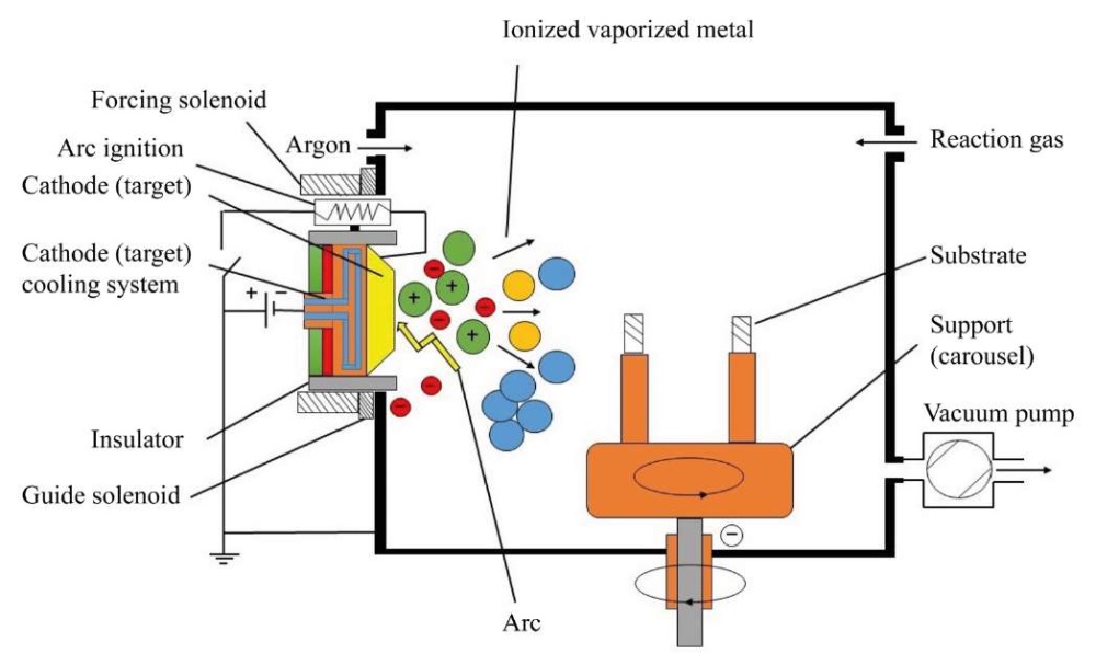
Fig. 1. Scheme of vacuum-arc coating method
The cooperation of academic institutes and universities in Russia has significantly influenced the development of the theory and practice of the new direction. Vacuum-arc technologies are also actively developing in foreign research centers: Lawrence Berkeley National Laboratory (USA), Sydney University of Technology (Australia), Cambridge University (Great Britain), Fraunhofer Institute for Material and Beam Technology (Germany), Wuhan University of Science and Technology (China), etc. [2].
The main unit of vacuum-arc installations is an electric arc evaporator. For uninterrupted operation during coating application, a reliable starting of the evaporator, a stable arc discharge at a given current value, and localization of cathode spots are required. It is also important to have a simple design for quick replacement of ignitions and cathodes, and not to exceed the minimum droplet phase in plasma flows [2].
The authors analyzed this coating application method and noted a disadvantage — the formation of a droplet phase with a size of 0.1–40 μm. Due to this, surface heterogeneity is formed, which causes:
The above-mentioned disadvantages contribute to the formation of structural defects. To reduce the droplet phase, plasma flow separation using a magnetic field, and optimization of the electrical parameters of the vacuum coating installation are used.
Processes in the Cathode Region of the Arc. CS contain erosion products, which are characterized by three phases: microdroplet, vapor, and ionized [7]. The latter predominates when it comes to evaporation in cathodes made of refractory materials [8]. In cathodes made of low-melting metals, the ionized phase accounts for up to 10% [9]. Note that in the plasma flow of a molybdenum arc, the ionized phase accounts for 80–90% of all phases [10].
G.A. Mesyats et alias [8] developed an ectonic theory that described processes in the cathode region of a vacuum arc. According to this theory, the beginning of the CS cycle is the explosive emission of electrons (EEE), which contributes to the appearance of plasma. The potential difference between the electric discharge and the plasma is called the cathode fall potential (CFP). Its value is close to the value of the ionization potential of the metal — and this is the key feature of the phenomenon described. To determine the currents transferred through the CS, two of their characteristics are used — the minimum current and the average value. The minimum (threshold) current is the current at which the CS and arc exist. The parameters of the CS and the threshold current are the major characteristics of the cathode region and the arc discharge [11].
There are three types of cathode spots. The first is observed at the beginning of the arc discharge and moves at a speed of 100–150 m/s [12]. The second is characterized by a more than twofold increase in evaporation and movement at a speed of 50–75 m/s [13]. The third type of CS is considered the most harmful and affects the formation of the droplet phase in vacuum-arc installations. The size of the CS cells depends on the cathode material. For example, the authors [14], studying the formation of CS, have come to the conclusion that for a copper cathode, the size of the CS is about 50–80 μm. It consists of fragments of 5–30 mm and brings current of 10–30 A. The life cycle of the CS is approximately 10–7–10–9 s in craters with a diameter of 1 μm. At the same time, at a distance from the cathode of 2⋅10–4 cm, the multiplicity and acceleration of ions increase.
The authors [15] have determined that when some cells in the CS disintegrate, others are generated. The process can also occur outside the boundaries of a given CS, but within its plasma halo. This is how other cells are formed and, consequently, a new CS. In [15], it is concluded that CS move a distance of up to 300 μm. As the discharge current increases, the number and size of CP cells grow. Then, the CS is divided into fragments that repel each other [10].
In the early 20th century, J. Stark established that in the presence of a magnetic field perpendicular to the movement of the CS, it moved against the action of the Ampere force [16]. In the case of the CS of the 1st type, a strong plasma flow with a speed of 5–10 km/s will arise. The halo formed in the CS of the 2nd type has a plasma glow and moves in the opposite direction.
From [17], the conditions for changing the speed of the CS movement are known. It grows if the magnetic field induction and the discharge current passing through the cathode increase. It falls with an increase in temperature and arc current.
R. Tanberg has found that the CS cells emit plasma jets at a speed of (1–2)·10⁶cm/s. The speed depends on the cathode material and the electrical parameters of the vacuum installation. Tanberg determined the composition of the plasma jets: electrons, ions, drops of cathode material, and neutral atoms [18].
Considering the operation of the CS cells, we note that the consumption of the cathode mass directly depends on the erosion products and phase. In the ionized phase, the consumption is constant, but when the drop phase appears, it grows in accordance with the increase in the discharge that passes through the CS [2]. The erosion coefficient depends on the current, temperature and material of the cathode (in low-melting materials, destruction occurs faster than in refractory materials).
In [19], the dependence of the erosion coefficient (Кэ) on the evaporation temperature for Al, Cu, stainless steel and titanium carbide is considered. It has been found that Кэ for Al, Cu and stainless steel depends on the evaporation temperature, and for titanium carbide in a given range of evaporation temperatures, Кэ does not practically increase. This can be explained by the fact that erosion in this case is a process of intensive evaporation of the cathode due to the uneven magnetic field of refractory materials.
To reduce the erosion coefficient, it is required to apply the coating with an increase in pressure of 10–3–101 Pa. In this case, the 1st type of CS will be actively formed, which will lead to a greater return of evaporated particles to the cathode surface. This phenomenon is less often observed in the 2nd type of CS. From this, we can conclude that the erosion coefficient of the 1st type of CS is less than that of the 2nd. If we consider the “gas – metal” pair, the maximum reduction in cathode mass consumption occurs with an increase in the discharge current and depends on the formed gas compounds with the evaporated material [20].
Thus, having considered the features of the formation of a vacuum-arc discharge and cathode spots, we can conclude that for stable implementation of vacuum-arc deposition, cathode materials with close values of the threshold current of the vacuum-arc discharge should be selected.
Processes on the Anode and Substrate. When the anode is applied, the vapor evaporating from the cathode surface condenses. The anode receives plasma energy. At the same time, its surface must have heat removal to the anode and perform reverse radiation into the plasma with subsequent evaporation of the anode material [21].
It is necessary to reduce the size of the anode to heat it to the melting and evaporation temperature. In this case, it is possible to apply coatings from the anode material with relatively high adhesion. When the anode is cooled to room temperature, brittle porous coatings with a high concentration of internal stresses are formed on its surface.
The energy of ions bombarding the substrate consists of their initial energy and the energy acquired in the Debye layer adjacent to the substrate when a negative potential is applied to it [1]:
 (1)
(1)
where Еi — ion energy; Е0 — initial energy; Z — ion charge multiplicity; Uп — substrate potential.
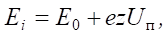
The authors [22] revealed the dependence of the deposition rate on the substrate potential when applying plasma flows of chromium, molybdenum, zirconium and titanium (Fig. 2).
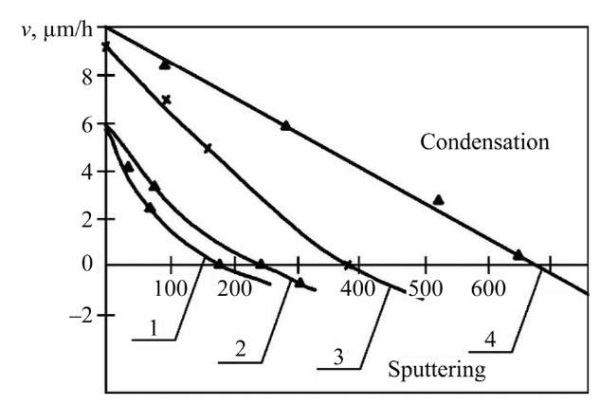
Fig. 2. Dependence of the deposition (sputtering) rate on the substrate potential under interaction with plasma flows of chromium (1), molybdenum (2), zirconium (3) and titanium (4). Substrate material — steel 30, nitrogen pressure — 2.66×10⁻³ Pa [22]
From Figure 2, it can be concluded that the potential value at which the processes of condensation and sputtering come into equilibrium depends on the nature of the evaporated material. As the potential value of the substrate increases, its material and the deposited particles are sputtered. Removal of substrate atoms (contaminants) leads to an increase in its temperature. Bombardment of hard alloy plates by chromium and titanium ions in a high vacuum at a potential of 1,000 V increases their average bending strength by 10–15% and reduces strength variation by 40–80% in a few minutes [23]. When the coating is subsequently applied, a diffusion zone up to 2–2.5 µm wide is formed. This treatment provides high adhesion of the coating to the substrate and makes it possible to harden steel with vacuum-arc coatings without losing their physical and mechanical characteristics [14]. With increasing gas pressure, the rate of discharge and speed decrease. This occurs when the active gas is released, which forms compounds with the evaporated gas.
Coatings Obtained Using the Vacuum-Arc Method. The vacuum-arc method (VAM) is used to obtain wear-resistant protective coatings with high physical and mechanical characteristics and a low friction factor. Over the years of developing vacuum technologies, scientists have produced numerous types of coatings for various branches of mechanical engineering. The most famous coatings are nitride (TiN, TiCN, TiAlN, TiMoN, TiSiN) and nanolayer composite (TiN/NbN, TiN/AlN, CrN/TiN, TiN/AlTiN) ones. Recently, the development of multicomponent high-entropy coatings has become a challenge.
Coatings obtained by VAM based on TiN with a nitrogen content of 37.5–52 at.% have been widely studied. Their main feature is a cellular microrelief with a cell size of 0.5–3 μm. The coating can contain two phases: Ti2N with a hexagonal close-packed (hcp) lattice, and TiN with a face-centered cubic (fcc) lattice. Another characteristic of the coating is a columnar structure. The diameter of the columns is 200 nm, grains with a diameter of 25–75 nm are elongated in the direction of growth [2].
In nitride coatings, nitrogen affects microhardness. With increasing nitrogen pressure in the chamber, microhardness increases to 35–53 GPa, and with further growth, it decreases to 20–24 GPa. This is explained by a decrease in the activation of nitrogen particles at a pressure of more than 1 Pa [2]. Note that the electrical conductivity of the coatings in question depends on the nitrogen content. The friction factor is determined by humidity. If it is low (10%), then the friction factor for chromium steel reaches 0.8, at 50% humidity — about 0.6, and during running-in — about 0.2.
TiCN (titanium carbonitrides) coatings are formed through mixing N2 with C₂H₂ or CH4. They have a columnar structure with a column width of 260 nm. When acetylene is added, the microhardness increases to 50 GPa. Titanium carbonitrides are almost twice as resistant to erosion (compared to TiN coatings) [24].
Coatings Ti1–хAlхN are substitution solid solutions with a cubic lattice of the B1 TiN type at 0 ≤ х ≤ 0.6. They are highly resistant to oxidation at extensive temperatures. Microhardness grows to 30 GPa with an increase in aluminum in the coating composition and the formation of aluminum nitride [25]. The authors [26] found that when applying Ti50Al50N coating with a decrease in reference voltage from –300 V to –150 V, the concentration of aluminum in the coating composition decreased, and this affected the microhardness. With a decrease in reference voltage by 30 V, the microhardness value increased from 29.1 to 34.5 GPa.
The authors [27] applied a TiN coating by the vacuum-arc method and introduced MoS2 into it through spraying molybdenum disulfide using the magnetron method. It was found that when introducing MoSx, the hardness increased significantly (up to 30 GPa). The friction factor decreased to 0.15, and the wear rate decreased by 20 times.
Coatings TiSiN have attracted the interest of scientists because Si is an alloying element of transition metal nitrides. It is chemically related to nitrogen and has a minor atomic radius (if we are talking about transition metals). This is why TiSiN coatings have a high microhardness value (30–45 GPa) and a low elastic modulus (200–250 GPa). During tribological tests, silicon forms SiO2 compound, and this solid lubricant reduces the friction factor to 0.5 [28].
When creating nanolayer composite coatings, layers of metals with different physical-mechanical properties, but close thermal expansion coefficients, alternate. The authors [29] studied nanolayer composite coatings made of materials with nanohardness of ~20 GPa. The TiN/NbN coating was found to have high nanohardness. The nanohardness of the TiN/VN coating was 55 GPa, and this is a very high figure for a nanolayer coating.
The use of the VAM is important in the creation of combined MeC(MeN)/a-C:H coatings with alternating nitride and carbon layers. Thus, in [30], TiAlN/DLC-Ti coatings were compared to DLC-Ti. The wear resistance of the combined coatings turned out to be twice as high as that of DLC-Ti, due to an increase in nanohardness to 24 GPa and Young's modulus — to 230 GPa.
In [31], the effect of ion implantation on the adhesive strength of TiN and Ti coatings was studied. Before applying TiN coating with Ti sublayer, U8A steel substrate was irradiated by argon ions with doses from 0 to 1017 ion/cm2. For TiN obtained on an irradiated substrate up to 1017 ion/cm2, the adhesive strength increased to 11.3 N. This is twice as much as the adhesive strength of TiN on a non-irradiated substrate. In the case of Ti monocoating, it was found that on a sample without implantation, peeling occurs at minimal indenter loads, and with irradiation of 3·1016 and 1.5·1017 ion/cm2, the adhesive strength increases by 1.8–2.5 N. These values are typical for soft coatings, which include titanium. Thus, ion implantation of the substrate increases the adhesive strength of TiN and Ti coatings.
In [32], MoTiN and MoСuN coatings were obtained by the vacuum-arc method, and the adhesive strength was determined using scratch testing. It was found that MoTiN coatings had hardness of up to 40 GPa and an adhesive strength — up to 22 N. This is significantly higher than that of MoCuN. Its hardness did not exceed 22 GPa, and the adhesive strength was no more than 4 N. The authors [32] explained the results by the structure of the coatings being formed. In the first case, a solid solution based on titanium nitride TiN was formed, in the second — a mixture of molybdenum nitride Mo2N and free copper.
Thus, a review of the literature on coatings obtained by the vacuum-arc method allowed us to draw certain conclusions. Such coatings are used to protect the surface of various tools. If we are talking about heavily loaded friction units, wear-resistant and antifriction coatings are used. It is possible to use different materials and combine application technologies to obtain combined coatings, such as TiMoSxN, MeC(MeN)/a-C:H.
Magnetron Sputtering Method. Magnetron sputtering involves bombarding the target surface by high-energy ions of the working gas (Ar, N2, O2, CH4) in glow discharge in vacuum of 10–3–10–2 Pa at a temperature of 100–250°C. This is one of the most common techniques for producing thin films. When sputtering target atoms, secondary electrons are emitted, which maintains the existence of plasma. High sputtering speed is achieved through increasing the ion current density due to a strong magnetic field [33].
The first magnetron sputtering systems (MSS) appeared in the early 1970s. At that time, cylindrical coaxial MSS of normal and inverse type were used. Their main problem was nonregular sputtering of the material due to the escape of electrons along the magnetic field lines. In this regard, the installations were modernized [34], technologies were developed, new types of magnetrons were created and introduced into production. Let us name some of them:
The diagram of an unbalanced magnetron is shown in Figure 3.
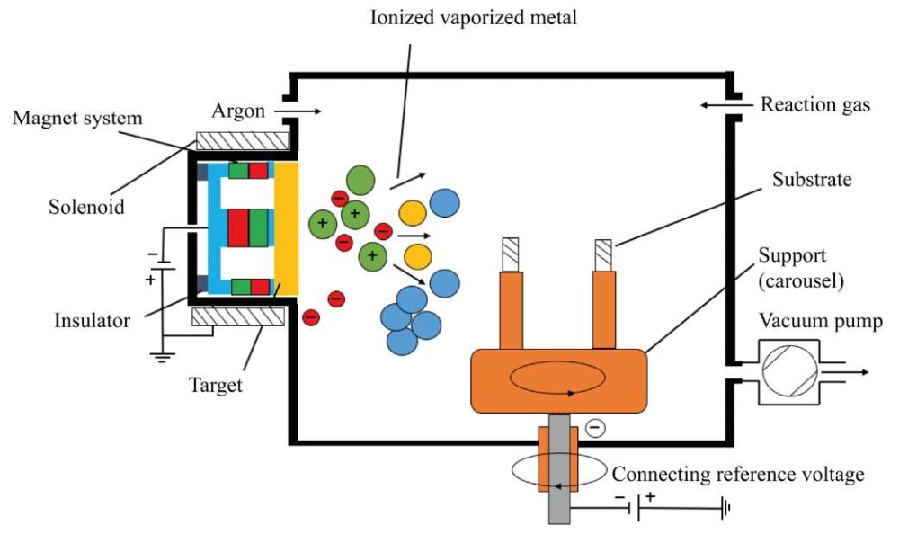
Fig. 3. Unbalanced magnetron circuit
The main elements of the device are: a cathode-target, an anode, and a magnetic system. Magnetrons are made so that a magnetic field is induced in parallel in the near-surface region of the target. As a result, secondary electrons are accelerated towards the targets. One magnetic pole is located in the center, and the second is at the edges of the cathode. This provides capturing the electrons that do not bombard the substrate itself. Thereby, the heating temperature of the target is reduced, but the degree of plasma ionization is increased [35].
The main advantages of this approach [36]:
Among the most noticeable disadvantages are:
Currently, it is required to obtain nitride and high-entropy coatings using magnetron sputtering. These include combined coatings, high-entropy coatings (HEC), as well as:
Let us consider the main results of studies on coatings obtained by magnetron deposition method.
The authors [37] have determined that the magnetron type is suitable for depositing titanium nitride coatings with a thickness of 1 nm to 1 μm. For this purpose, they used a facility with pulsed sputtering on silicon substrates [38]. To maintain process stability, they varied the distance between the target and the substrate in the range of 50–100 mm and changed the nitrogen feed rate into the working chamber. Analysis of the obtained titanium nitride (TiN) coating has shown that with a decrease in the distance between the target and the substrate, the mechanical properties of the coating deteriorate, its quality decrease. This is explained by the fact that due to the close distance, the thermal effect increases, and the effect of thermal annealing occurs.
The authors [39] studied the growth rate of coatings on semiconductor substrates at room temperature. The feed rate and operating power of the magnetron control unit were varied.
Using the magnetron deposition method, superhard Ti1–xAlxN coatings were obtained at 0.5 ˃ х ˃ 0.6 with microhardness of 40 GPa. It is worth noting that the lattice parameter for TiN decreased from 0.4255 nm to 0.417 nm [40].
Coating TiMo(SN) alternated layers of molybdenum disulfide MoS2 with TiN, so the microhardness increased from 4 GPa to 15–35 GPa with a friction factor of 0.02–0.1. MoS2 was evaporated using a magnetron, and TiN was deposited using vacuum arc deposition. MoS2Ti with nanohardness of 10 GPa and Young's modulus of 142–169 GPa was applied to a CrN coating with nanohardness of 24–30 GPa and Young's modulus of 352–418 GPa. Due to molybdenum disulfide in the coating composition, the friction factor decreased by 91–95%, wear — by 50–95% [41]. Pure molybdenum disulfide was applied using a magnetron and studied without removing it from the chamber. Its friction factor was 0.002 [42]. Thus, adding MoS2 to the coating composition reduces significantly the friction factor.
Nanostructured multilayer TiN/AlN coatings obtained by magnetron method showed high results in micro drilling and turning in comparison to TiN coatings. When drilling fiberglass, the durability of drills with TiN/AlN coating was 40% higher than without it, and 25% higher than with TiN coating [43].
An important property of coatings obtained by the magnetron method is adhesive strength. It provides evaluating the resistance of the surface to delamination. In [44], the adhesive strength of nitride coatings CrN, TiN on carbon steel S235 is evaluated. It is found that the application of a multilayer structure (sublayer + coating) provides for the adhesion improvement. Thus, for CrN coating, the value of adhesion strength without a sublayer is 37 N, with a Cr sublayer — 40 N. The indicators for TiN coating are 16 N (without a sublayer) and up to 24 N (with Ti sublayer). Adhesion strength increases when applying coatings to a harder base in the form of pure metals, close in composition to the basic coating.
The authors [45] studied the adhesive strength of AlTiNiAg and NiAg coatings obtained by the magnetron method. The coatings were applied to silicon structures and molybdenum thermocompensators of power semiconductor devices with annealing in vacuum, hydrogen, and without it. The adhesive strength was studied by scratch testing. The maximum adhesive strength was found in samples of a silicon structure with a four-layer AlTiNiAg coating (21.7 N) after annealing in vacuum. For molybdenum thermocompensators, the two-layer NiAg coatings annealed in vacuum turned out to be the strongest (13.5 N).
The review of the literature has established that magnetron sputtering is characterized by:
The method is widely used for applying thin layers to semiconductors, glass, and obtaining self-lubricating coatings with a low friction factor.
Coating Growth and Structure Formation Mechanisms. When coatings are applied, the structure formation occurs in several stages (Fig. 4). At the first stage, atoms are adsorbed from the plasma flow. The atom continues to move until a chemical bond with the surface atoms is formed. At this stage, the atom may not form a chemical bond with the substrate surface, depending on the material being applied and the method of application. After the atom is fixed to the surface, chemical bonds are formed with the newly arrived atoms — this is how the coating is formed. Diffusion processes may occur between the substrate and the film.
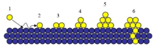
Fig. 4. Scheme of formation of coating structure: 1 — deposition of atom from plasma flow; 2 — movement of atom; 3 — formation of adsorption chemical bond of deposited atoms from plasma with substrate; 4, 5 — formation of coating cells; 6 — penetration of plasma atoms into substrate material
When an atom is adsorbed on a substrate, surface tension arises. The bonds between the atoms of the substrate and the coating are lengthened, therefore, the energy depends on the type of bond formation. The achievement of energy equilibrium is facilitated by the force of surface diffusion, which is determined by the temperature of the substrate and the energy of the atoms.
Figure 5 schematically shows three mechanisms of coating growth.
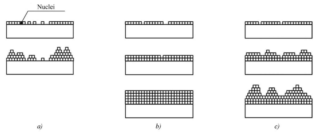
Fig. 5. Schematic representation of three mechanisms of coating growth: a — island, Volmer-Weber; b — layered, Frank-van der Merwe; c — mixed, Stranski-Krastanov
The layer-by-layer mechanism operates if the bond strength between the coating atoms is less than the bond strength between the coating and substrate atoms, and also if these forces are equal. In this case, the mismatch of the crystal lattices should be minimal. The condition for the island mode to be realized is that the bond between the coating atoms should be stronger than the bond between the coating and substrate atoms. The mixed mode occurs when the crystal lattice parameters of the coating and substrate are mismatched [1].
B.A. Movchan and A.V. Demchishin [46] were the authors of the first significant works on the mechanism of coating growth. In parallel, they developed physical deposition methods and proposed a diagram of the zone structure of coatings depending on the substrate temperature. The researchers have clearly shown that the microstructure of PVD coatings is conditionally divided into three zones with different homologous process temperatures (Thm — ratio of the melting temperature of the coating to the substrate temperature Тпл/Тпод).
This model was improved by J.A. Thornton [47]. He introduced the partial pressure of argon in the chamber and the intermediate zone T (between the first and second) into the diagram. The coating density in zone T is higher than in the neighboring zones, the surface roughness is less.
During the formation of the microstructure at different stages [48], nuclei are formed, islands increase in size and coalesce, polycrystalline islands and channels appear, and films grow (Fig. 6).
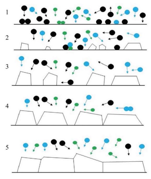
Fig. 6. Schematic representation of structure formation processes: 1 — formation of nuclei; 2 — growth of islands; 3 — contact and coalescence of islands; 4 — coarsening of grains, formation of polycrystalline islands and channels; 5 — development of structure and growth of coating [48]
The formation of nuclei begins with the growth of isolated islands on the surface of the substrate. The size of the islands is 20–30 Å [49].
During the process of island coalescence, a driving force for grain coarsening is created due to the surface diffusion of atoms and grain boundary movement. The resulting low-energy islands absorb others. As a result, the new single-crystal island contributes to a decrease in the energy of the entire surface. The coarsening of the structure under coalescence depends on the temperature, the size of the islands, and determines their orientation [50]. At low temperatures and large island sizes, coarsening occurs more slowly due to grain boundary migration. During the coalescence of crystals, the grains coarsen until their boundaries become large and immobile.
It should be noted that vacuum technologies require preparation of the substrate for coating application. This is important because during coating growth, defects, such as porosity, internal stress, deformation of crystallites and the crystal lattice, may appear. They occur both in the vacuum-arc method and in the magnetron method.
If there is macro-roughness on the sample surface, high internal stresses are formed in the coating, which lead to delamination. Micro-roughness causes porosity of the coating and worsens its physical and mechanical properties. Defects appear on the surface and increase with the growth of the structure. The formation of a droplet phase is possible not only in vacuum-arc coatings, but also in magnetron sputtering of refractory materials [50]. Droplets on the surface are formed rather quickly and stochastically. The result is screw dislocations, which cause spiral growth of crystals. As shown in [51], during the coating process, the “craters” formed due to the separation of large particles are quickly filled with ions of the applied material. Therefore, defects due to the droplet phase are substructural and do not greatly affect the structure and properties of the coating.
Properties of High-Entropy Alloys. Research into HEA and coatings based on them has begun relatively recently. In 2002, Professor Jien-Wei Yeh (National Tsing Hua University, Taiwan) developed a new class of materials [52]. Physical and mechanical properties of HEA have attracted the attention of scientists. Over 20 years, about 5,000 papers on HEA have been published [53]. A characteristic feature of HEA is the mixing of 5 or more elements (each accounts for 5–35% at.). In this case, a substitution solid solution is formed. It is single-phase. A phase with a bcc-, fcc-, or bcc+fcc lattice is formed [54].
The key feature of HEA is the high entropy of mixing. It promotes the formation of solid solutions, which reduces the likelihood of intermetallic compounds. As a result, HEA are characterized by thermal stability, corrosion and wear resistance, increased plasticity at low temperatures, and resistance to ionizing radiation [55]. The average atomic concentration (el/at.) is often used to characterize the atomic-crystalline structure of multicomponent systems. In high-entropy alloys:
The properties of the HEA are described by 5 parameters [57]:
All criteria are calculated using expressions taking into account the atomic concentration of each i-th component of alloy ci.
The entropy of the HEA consists of:
In a high-entropy alloy, configurational entropy (ΔSk) is higher than that of the components ΔSB, ΔSv, ΔSm. But this is not typical for common metals. Therefore, in high-entropy alloys, a single-phase solid solution is formed due to ΔSk. With an increase in the number of elements (n), ΔSk grows. This reduces the Gibbs energy ΔG = ΔH – T ΔS (ΔH — enthalpy, T — absolute temperature, ΔS — entropy) and maintains thermodynamic stability [59]. The entropy and enthalpy of high-entropy alloys are determined from the expressions:
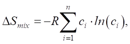 (2)
(2)
 (3)
(3)
where R — absolute gas constant, R = 8.314 J/(K×mol); ci — atomic concentration of element i (at.%);  — enthalpy of binary alloys near the melting point of elements АВ, which are part of HEA.
At equiatomic concentration of components, the atomic concentration of an element is defined as ci=1/n. This means that the entropy level is DSmix = R × ln(n). At n≥5, the configurational entropy is: DSmix ≥ 13.4 J/(K×mol), and the alloy is considered high-entropy.
Figure 7 shows the dependence of the mixing entropy on the number of elements [60].

Fig. 7. Dependence of mixing entropy on the number of elements [60]
In metals and simple alloys, atoms can occupy a place in the crystal lattice with equal probability. This is how they differ from high-energy alloys, in which the crystal lattice is distorted due to the substitution of several elements with different atomic sizes. If the sizes of atoms in the alloy structure differ significantly, then internal stresses are formed, which cause an increase in the strength properties of the coatings [58].
The distortion of the crystal lattice determines the strength of the HEA and reduces diffusion. Slowing down the diffusion enhances the formation and stabilization of the solid solution of the HEA, and also reduces the rate of crystal growth. The possibility of forming an amorphous structure is opened up, but the thermal and chemical stability increases [61].
To predict the formation of solid solutions, the difference in atomic radii (in %) is used. This parameter is denoted by δ. The formation of a structural phase in HEA is determined by:
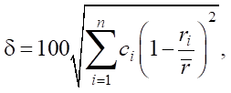 (4)
(4)
where n — number of components in the alloy; ci — content of the i-th component (at. %); ri — atomic radius of the i-th component;  — average atomic radius
 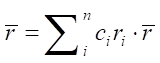 .
.
To describe the difference in atomic sizes, paper [62] proposes to classify the elements of the HEA. Table 1 shows the classification and elements depending on the atomic size δ.
Table 1
Classification of Elements by Atomic Size [62]
|
Atomic size (radius) group |
Group elements |
|
Minimum |
Si — 0.117 nm |
|
Small (about 0.125 nm) |
Cr, Co — 0.125 nm, Fe — 0.126 nm, Cu — 0.128 nm, V — 0.132 nm |
|
Medium (about 0.145 nm) |
Al — 0.143 nm, Ti — 0.145 nm, Nb — 0.159 nm |
|
Large (about 0.160 nm) |
Hf — 0.159 nm, Zr — 0.160 nm |
|
Out size (about 0.180 nm) |
Y — 0.180 nm |
To exclude the formation of Laves phases, intermetalledes, and amorphous phases, theoretical parameter Ω is proposed, which takes into account the melting temperature of the components:
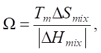 (5)
(5)
where Tm — average melting point of the components.
The average melting point is estimated together with the difference in atomic radii. High value Ω ˃ 1.1 and small value δ ˂ 6.6 predict the formation of solid solutions.
The authors [57] proposed a variant of predicting the formation of solid solutions by electronegativity:
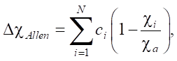 (6)
(6)
where ci — Pauling electronegativity for the i-th element; ca — average electronegativity.
In this case, electronegativity is the average ionization energy of the valence electrons of free atoms. The authors [63] determined that solid solutions were formed in the ranges 3 < ∆χ < 6 and 1 < δ < 6%. It was also established that solid solutions with a bcc lattice exist with a greater mismatch of atomic radii and lower electronegativity (in comparison to the conditions for the fcc lattice).
The valence electron concentration (VEC) affects the stability of the structure of solid solutions and is defined as a weighted average value:
 (7)
(7)
where ci(VEC)i — VEC for the i-th element.
When determining the electron concentration, special attention is paid to the stabilization of the solution due to the accumulation of electrons at low-energy levels [59]. The density of the structure and bonds per atom are estimated. At VEC ≥ 8, one fcc phase is formed. At 6.87 ≤ VEC ≤ 8, the bcc and fcc phases are mixed. At VEC ≤ 6.87, the alloy contains only the bcc phase. In [64], the influence of VEC on the formation of AlCoCuFeNi alloy lattice is analyzed. The bcc lattice was formed at low values of the valence electron concentration, and the fcc lattice — at high values.
The theoretical analysis allows us to determine the conditions for the formation of a solid solution:
Composition of High-Entropy Alloys and Coatings. About 40 elements are known, from which approximately 500 materials can be obtained that meet all the criteria of high-entropy alloys [56].
In the literature, the elements of the HEA are divided into families. The first one is the most studied, it is based on 3d-transition elements: Fe, Co, Cr, Ni, Mn, Al, Ti, Cu, V. These are elements with high hardness, corrosion and wear resistance. One of the first and well-studied high-energy alloys is CoCrFeMnNi. This is the so-called Cantor alloy, proposed in 2004. The second family of HEA is based on refractory metals (Hf, Ta, Mo, Nb, V, W, Cr, Zr, Ti). The third includes low-melting elements (Al, Sn, Be, Li, Mg, Ti, Sc, Si, Zn). The fourth includes rare earth elements (Gd, Dy, Lu, Tm, Tb, Y). The fifth consists of high-entropy bronzes and brasses (Zn, Cu, Ni, Mn, Al, Sn). The sixth, the youngest, unites Au, Ag, Cu, Co, Cr, Ni, Pt, Pd, Ru, Rh [57]. Some elements belong to different families.
To reach high values of hardness and strength in modern nitride HEA, transition d-metals with negative enthalpy (ΔH) are used. The composition of nitride HEA and their hardness values are given in Table 2.
Table 2
Hardness Values of High Entropy Alloys [59]
|
Composition |
Hardness (GPa) |
|
(AlCrNiSiTi)N |
15 |
|
(TiVCrZrY)N |
18 |
|
(AlCrMoSiTi)N |
25 |
|
(TiAlCrSiV)N |
31 |
|
(AlCrTaTiZr)N |
35 |
|
(AlMoNbSiTsTiVZr)N |
37 |
|
(AlCrNbSiTiV)N |
41 |
|
(TiHfZrVNb)N |
43 |
The authors [64] have found that the strength properties of high-entropy alloys are higher than those of numerous metallic alloys. The yield strength and Vickers hardness values of HEA are high — at the level of metallic glass, titanium and nickel alloys. NbCrMo0,5Ta0,5TiZr and Al2,0CoCrCuFeNi occupy a special place. Their Vickers hardness is close to 1000, and the elastic limit exceeds this value.
Heat-resistant HEA are widely used and could be applied in the aerospace industry. The first such alloys based on Mo, Nb, Ta, W, V, had serious drawbacks — high density and low corrosion resistance. The problem is solved by replacing the specified elements with others — Cr, Ti, Zr, Al [65].
An important characteristic of heat-protective alloys and coatings is the thermal coefficient of linear expansion (TCLE). It affects the adhesion between the coating and the substrate, since in coatings with a low TCLE, thermal transformations occur at high temperatures, which cause “peeling”, delamination, and further destruction of the coating:
To solve the problem of coating destruction under the influence of temperature, it is proposed to use a thermal barrier layer of high-entropy NiAlCrWTaYSiHf coating with a thickness of 20–30 μm [66]. This allows reducing the diffusion exchange, which causes an increase in the TCLE and adhesion between the combined coating and the substrate. It should be noted that for tribological coatings, this criterion is not relevant due to the small thickness of coatings.
The authors [67] performed annealing of two coatings:
The annealing was carried out at a temperature of 900°C for two hours. The study of the microstructure showed that oxide particles were formed on the surface of the coating. Their thickness for the coating (Al23,1Cr30,8Nb7,7Si7,7Ti30,7)50N50 was 100 ± 12 nm, for the coating (Al29,1Cr30,8Nb11,2Si7,7Ti21,2)50N50 — 80±7 nm. Under the oxide films, the structure of the coating did not change. The study confirmed that high-entropy coatings have high oxidation resistance and, in that indicator, surpassed most of the coatings in use.
To obtain high-entropy coatings, PVD deposition methods are widely used: vacuum arc and magnetron. The properties of several types of coatings from high-entropy alloys have been studied in detail: (AlCrTaTiZr)N, (TiAlCrNbY)C, (FeCoNiCrCuAl)N, (AlCrMoSiTi)N, (AlCrNbSiTiV)N, (TiAlCrSiV)N, (AlMoNbSiTaTiVZr)N, (TiVCrZrY)N, (TiHfZrVNb)N, (TiVCrZrHf)N.
The authors [68] obtained high-entropy nitride coatings using vacuum-arc deposition and magnetron sputtering. It has been found that metals of groups IV–V tend to form nitrides with a stable structure. The microstructure and hardness of high-entropy nitride coatings depend on the parameters of the deposition process. In processes with the same parameters, expansion in the number of components leads to an increase in the hardness of the coatings. Improved tribological properties are achieved by adding Mo or W elements, which reduce the friction factors. The addition of Al and Si increases oxidation resistance due to the formation of protective oxide layers.
In [69], the production of a CoCrFeNi film with a thickness of about 1 µm using ion-beam sputtering is shown. A film of similar composition and thickness was also obtained using the high-pressure torsion (HPT) technique. In the comparative analysis of the films, the textures and sizes of the crystallites were determined by X-ray diffraction, and the hardness was measured through nanoindentation. The hardness of the film obtained by PVD was 9.8 ± 0.3 GPa. This was greater than that of the HPT sample (7.3±0.3 GPa). The grain size of the crystallites was about 20 nm.
The authors [70] obtained a CuTiZrCrNi coating on a substrate made of AISI 201 steel using magnetron sputtering. It was found that after tribological tests, the coating wear was 3∙10–4 g/min. The friction factor of the CuTiZrCrNi coating on copper was 0.041, on aluminum — 0.066.
In [71], a CrTiNiZrCu coating on an AISI 201 steel substrate obtained through magnetron sputtering is described. Atomic force microscopy showed a cellular nanostructure of the high-entropy coating. Several models of its formation are described, and the main reasons for the formation of such nanostructures are established.
The authors [72] used a magnetron to form a CrNbTiMoZr coating with a nanohardness of 9.7 GPa and high tribological properties. In [73], multicomponent coatings based on AlCrTiV with the addition of Cu and Mo were considered. The researchers concluded that the corrosion properties of the coatings significantly exceeded the properties of the steel substrate AISI 304. This was explained by the formation of stable oxides.
In [74], the creation of a TiTaHfNbZr coating with a thickness of 800 nm on a substrate of Ti-6Al-4V alloy was described. It was obtained using magnetron sputtering. The tribological research showed that with an increase in load from 1 N to 3 N, the wear of the substrate without a coating increased significantly, whereas for samples with a TiTaHfNbZr coating the wear was insignificant.
In [75], vacuum arc and magnetron methods were used to obtain a (TiAlSiCrNiCuOC)N coating with a B1-type lattice, identical to TiN, with a superhardness of 47 GPa and a thermal stability of 900–1,000°C.
In [76], the production of a high-entropy nitride coating (TiZrHfVNb)N using the vacuum-arc method is shown. The reference voltage changed from –40 to (–200) V. The coating thickness was 4.78 μm. The results of nanoindentation showed that with a growth of the reference voltage, the following parameters increased:
Tribological tests allowed us to establish the friction factor (1.193). The coating had low wear of 0.039 I·10–5 (mm³/N/mm).
Several works are devoted to the study of the structural-phase state and physical-mechanical properties of high-entropy coatings. The main results of the studies are presented in Table 3.
Table 3
Results of Studies on Structural-Phase State and Physical-Mechanical Properties of HEA
|
Name of coating |
Process variables |
Hardness H, GPa |
Young's modulus, GPa |
Structure |
Link |
|
(Al23,1Cr30,8Nb7,7Si7,7Ti30,7)50N50 |
Uc = –50 V |
16.00 |
305 |
fcc |
[77] |
|
Uc = –100 V |
36.10 |
440 |
|||
|
Uc = –150 V |
34.10 |
400 |
|||
|
(Al29,1Cr30,8Nb11,2Si7,7Ti21,2)50N50 |
Uc = –50 V |
25.00 |
330 |
fcc |
[77] |
|
Uc = –100 V |
35.00 |
390 |
|||
|
Uc = –150 V |
37.00 |
395 |
|||
|
(AlCrTaTiZr)N |
– |
34.00–35.00 |
340–355 |
fcc |
[78] |
|
(AlCrMoTaTiZr)N |
N = 40% |
40.20 |
370 |
fcc |
[79] |
|
N = 50% |
37.00 |
420 |
|||
|
(AlCrMnMoNiZrB0,1)N |
RN = N2/Ar = 0 |
7.10 |
163 |
Amorphous |
[80] |
|
RN = N2/Ar = 0.5 |
~10.00 |
~180 |
fcc |
||
|
RN = N2/Ar = 1 |
10.20 |
~180 |
fcc |
||
|
(TiZrNbHfTa)N |
Uc = –50 V |
22.50 |
170 |
fcc |
[81] |
|
Uc = –100 V |
33.00 |
276 |
|||
|
Uc = –150 V |
32.90 |
268 |
|||
|
(TiZrNbHfTa)N |
Uc = –50 V |
22.50 |
170 |
fcc |
[81] |
|
Uc = –100 V |
33.00 |
276 |
|||
|
Uc = –150 V |
32.90 |
268 |
|||
|
(TiZrNbHfTa)C |
– |
27.50 |
– |
fcc |
[81] |
|
TiZrNbHfTa |
5.40 |
– |
fcc + double (triple) bonds |
[81] |
|
|
(TiVCrZrHf)N |
Tподложки = 250°С |
41.00 |
~300 |
fcc |
[82] |
|
Tподложки = 350°С |
45.00 |
~310 |
|||
|
Tподложки = 450°С |
49.00 |
~320 |
|||
|
Tотжига = 300°С |
31.24 |
300 |
[83] |
||
|
Tотжига = 500°С |
11.85 |
250 |
|||
|
Tотжига = 700°С |
2.30 |
~60 |
|||
|
(TiHfZrVNb)N |
Uc = –50 V |
21.00 |
337 |
fcc |
[59] |
|
Uc = –100 V |
28.70 |
361 |
|||
|
Uc = –200 V |
29.50 |
373 |
|||
|
(TiVCrZrY)N |
N = 0% |
20.90 |
– |
hcp |
[84] |
|
N = 100% |
18.90 |
– |
The data in Table 3 allow us to conclude that to obtain high-strength coatings, it is required to introduce transition metals into their composition. The addition of nitrogen strengthens covalent bonds in the coating and significantly increases the hardness. Coatings based on HEA are multi-parameter; therefore, to change the values of nanohardness and Young's modulus, it is necessary to vary the process parameters during application: nitrogen supply, substrate temperature, reference voltage.
Research on high-entropy coatings is based on the study of the coating structure, physical-mechanical properties, and thermal stability. Less attention is paid to tribological studies. Table 4 summarizes their key known results.
Table 4
Results of Tribological Studies on High-Entropy Coatings
|
Name of coating |
Friction factor |
Wear intensity I 10–6 (mm³/N/m) |
Link |
|
(AlCrTaTiZr)N |
0.760 |
3.66 |
[85] |
|
(AlCrMoTaTiZr)N |
0.800 |
2.90 |
[86] |
|
(TiZrNbHfTa)N |
0.960 |
2.90±0.20 |
[81] |
|
(TiZrNbHfTa)C |
0.150 |
0.80±0.05 |
[81] |
|
TiZrNbHfTa |
0.870 |
17.00±1.00 |
[81] |
|
(TiZrHfVNb)N |
1.193 |
390.00 |
[59] |
Table 4 shows that high-entropy coatings have a high friction factor. Note that (TiZrNbHfTa)C has an extremely low coefficient (0.15). This is explained by the formation of a free carbon phase, which acts as a solid lubricant and reduces the friction factor. The high wear resistance of HEA is associated with an increase in hardness when alloying transition metals, nitrogen, and greater resistance to plastic deformation.
Research Methods for High-Entropy Coatings. The microstructure of the HEC is examined using optical metallography. Scanning electron microscopy (SEM) is used to study fine details. Its major advantages are high resolution and clarity. In addition, SEM works with several types of induced radiation. In addition to X-rays, reflected and absorbed electrons, as well as cathodoluminescence, are used. In this way, it is possible to study the surface relief, phase and orientation contrasts, and conduct micro-X-ray spectral and energy-dispersive analysis. In some cases, the capabilities of electron microscopy and cross-sectional research are combined.
The chemical composition of the coatings is determined by an energy-dispersive X-ray detector. It allows point probing or scanning of a section by the area of the figure or by the distribution map of chemical elements. To increase the accuracy of determining the elemental and phase composition of the coatings, X-ray photoelectron spectroscopy and Auger electron spectroscopy methods are used. Survey spectra are recorded from the surface of the coatings. They are used to study the qualitative and quantitative composition of the surface. In addition, the spectra are used to determine the electron lines of the chemical elements of the surface, which makes it possible to effectively determine the chemical bond. This allows us to judge the phase in which the element is included.
X-ray structural analysis is used to determine the crystalline structure of high-entropy coatings. For this purpose, reflections with maximum intensity are identified on the X-ray diffraction pattern. Based on them, conclusions are made about the phase composition, the size of the coherent scattering regions, the parameters of the crystal lattice, and the deformation of the crystal lattice of the coating [87].
Such stress-strain properties of the coating as hardness (H) and elastic modulus (E) are measured through nanoindentation. In this case, the load curves are analyzed using the Oliver-Farr method [88]. For indentation in continuous measurement mode, Berkovich diamond indenter is used. In addition to hardness and elastic modulus, it is possible to determine:
H/E — indicator of tribological properties. The higher it is, the higher the wear resistance. Materials with H/E < 0.04 belong to the coarse-crystalline group (metals and alloys), and materials with H/E ≈ 0.05 – 0.09 belong to the group of fine-crystalline and nanomaterials (ceramics, coatings).
The tribological properties of the coatings are determined using friction machines by the “ball — disk” or “pin — plate” scheme. Based on the test results, such coating characteristics as wear and friction factor are assessed.
Discussion and Conclusion. The literature analysis performed by the authors of the presented article makes it possible to:
One of the advantages of coatings obtained by vacuum-arc and magnetron methods is a wide range of materials for synthesizing coatings with high physical, mechanical and tribological characteristics.
Three classes of growth of coating formation are distinguished. The essence of the process is determined. This is nucleation with the growth of islands of 20–30 Å in size. We emphasize that any coating may have defects: porosity, internal stresses, deformation of crystallites and crystal lattice.
High-entropy alloys are formed by mixing five or more elements. High entropy promotes the formation of solid solutions. This feature determines thermal stability, wear resistance, increased plasticity at low temperatures, corrosion resistance, resistance to ionizing radiation. There are about 40 known elements that are included in high-entropy alloys; therefore, special criteria (parameters) have been developed for the precise selection of materials, prediction of stability and structural-phase state of high-entropy alloys:
Within the framework of this research, it is established that the issues related to nitride coatings obtained by vacuum-arc and magnetron methods are sufficiently explored in the literature. There are fundamental studies on the structure of coatings, their physical and mechanical properties, thermal stability. It is also known that high-entropy coatings are distinguished by high hardness with a face-centered cubic lattice, high thermal stability. Transition metals with the addition of nitrogen are widely used in the compositions of the coatings under consideration. The main type of high-entropy coatings is nitride. The coatings studied in this paper are characterized by a significant friction factor. However, due to their hardness and plasticity, they demonstrate high wear resistance.
It is difficult to say that high-entropy coatings can already replace traditional ones in mechanical engineering. However, over time, they will be widely used for elements that operate under high-temperature conditions.
Based on the literature analysis results, it should be noted that there is a limited number of papers considering this issue from the point of view of tribology. For further research, it is necessary to develop high-entropy coatings that will provide high hardness, wear resistance, and a low friction factor. This will make it possible to create coatings suitable for use in tribo-loaded units, and therefore, in the mechanical engineering production processes. Thus, it is expected to receive promising materials that will compete with traditional coatings.
1. GOST 2789–73. Surface Roughness. Parameters and Characteristics. Moscow: Standartinform; 2006. 8 p. (In Russ.) URL: http://www.omegametall.ru/Data2/1/4294847/4294847701.pdf (accessed: 29.07.2024).
1. Polityko KN, Manturov DS. Formation of PVD Coatings for Tribological Purposes. Trudy RGUPS – Transaction of RSTU. 2023;64(3):81–93.
2. Andreev AA. Vacuum-Arc Coatings. Kharkov: NSC KIPT; 2010. 318 p. (In Russ.)
3. Anders A. Cathodic Arcs. New York: Springer; 2008. 540 p. https://doi.org/10.1007/978-0-387-79108-1
4. Boxman RL. Early History of Vacuum-Arc Deposition. IEEE Transactions on Plasma Science. 2001;29(5):759–761. https://doi.org/10.1109/27.964470
5. Mattox DM. The History of Vacuum Coating Technology. Albuquerque, NM: Management Plus Inc.; 2002. 51 p. URL: http://www.astrosurf.com/astroptics/files/histoire_des_couches_anti-reflet.pdf (accessed: 03.09.2024).
6. Aksenov II, Andreev AA. Vacuum-Arc Ion-Plasma Coating Technologies in KIPT. Problems of Atomic Science and Technology. Series “Vacuum, Pure Materials, Superconductors”. 1998;2(3)/3(4):3–11. (In Russ.)
7. Zimin AM, Ivanov VA, Juttner B. Dynamics of Cathode Spots on the Beryllium Surface in Vacuum Arc Discharge. Problems of Atomic Science and Technology. Series “Thermonuclear Fusion”. 2001;(2):44–50.
8. Mesyats GA. Ectons in a Vacuum Discharge: Breakdown, Spark, Arc. Moscow: Nauka; 2000. 424 p. (In Russ.)
9. Cobine J, Ecker G, Farrall J, Greenwood A, Harris L. Vacuum Arcs: Theory and Application. Moscow: Mir; 1982. 432 p. (In Russ.)
10. Lunev VM, Ovcharenko VD, Khoroshikh VM. Investigation of Some Characteristics of Vacuum Metal Arc Plasma. Technical Physics. 1977;47(7):1486–1490. (In Russ.)
11. Zabello KK, Logatchev AA, Chaly AM, Shkolnik SM. Characteristics of the Statistical Distribution of the Current Transmitted by the Cathode Spot of a Vacuum Arc in Variously Oriented Magnetic Fields. Technical Physics. 2009;79(6):58–66.
12. Fortov VE, Alexandrov AF, Asinovsky EI, Gribkov VA, Didenko AN, Dykhne AM, et al. Encyclopedia of Low Temperature Plasma. Introductory Volume 1. Moscow: Nauka; 2000. 634 p. (In Russ.)
13. Juttner B, Puchkarev VF, Hantzsche E, Beilis I. Cathode Spots. In book: Boxman RL, Sanders DM, Martin PJ. (eds) Handbook of Vacuum Arc Science and Technology. Park Ridge: Noyes Publications; 1995. P. 73–281.
14. Raizer YuP. Physics of Gas Discharge. Moscow: Nauka; 1987. 592 p. (In Russ.)
15. Mattox MD. Handbook of Physical Vapor Deposition (PVD) Processing. Norwich, NY: William Andrew Publ.; 2010. 746 p.
16. Tsventukh MM, Barengolts SA, Mesyats VG, Shmelev DL. Reverse Motion of Cathode Spots of the First Type in a Tangential Magnetic Field. Technical Physics Letters. 2013;39(21):1–9. (In Russ.) URL: https://journals.ioffe.ru/articles/viewPDF/14640 (accessed: 03.09.2024).
17. Fang DY, Nürnberg A, Bauder UH, Behrisch R. Arc Velocity and Erosion for Stainless Steel and Aluminum Cathodes. Journal of Nuclear Materials.1982;111-112:517–521. https://doi.org/10.1016/0022-3115(82)90258-6
18. Granovsky VL. Electric Current in Gases. Steady State Current. Moscow: Nauka; 1971. 543 p. (In Russ.)
19. Nürnberg AW, Fang DY, Bauder UH, Behrisch R, Brossa F. Temperature Dependence of the Erosion of A1 and TiC by Vacuum Arcs in a Magnetic Field. Journal of Nuclear Materials.1981;103:305–308. https://doi.org/10.1016/0022-3115(82)90614-6
20. Aksenov II, Konovalov II, Padalka VG, Khoroshikh VM, Bren VG. Investigation of Cathode Erosion of a Stationary Vacuum Arc. Moscow: Atominform; 1984. 23 p. (In Russ.)
21. Borisov DP, Goncharenko IM, Koval NN, Schani PM. Plasma-Assisted Deposition of a Three-Layer Structure by Vacuum and Gas Arcs. IEEE Transactions on Plasma Science. 1998;26(6):1680–1684. https://doi.org/10.1109/27.747886
22. Aksenov II, Andreev AA, Bren VG, Gavrilko IV, Kudryavtseva EE, Kunchenko VV, et al. Coatings Obtained by Condensation of Plasma Streams in Vacuum (Ion Bombardment Condensation Method). Ukrainian Journal of Physics. 1979;24(4):515–525. (In Russ.)
23. Budilov VV, Shekhtman SR, Izmailova NF. Deposition of Vacuum Ion-Plasma Coatings on Turbine Blades of a Gas Turbine Engine with the Use of Discharge and the Hollow Cathode Effect. Russian Aeronautics. 2001;(1):76–78.
24. Kunchenko VV, Andreev AA. Titanium Carbonitrides Obtained by Vacuum Arc Deposition. Problems of Atomic Science and Technology. Series “Physics of Radiation Damage and Radiation Materials Science”. 2001;(2):116–120. (In Russ.)
25. Roos JR, Selis JP, Vancoille E, Veltrop H, Boelens S, Jungblut F, et al. Interrelationship between Processing, Coating Properties and Functional Properties of Steered Arc Physically Vapour Deposited (TiAl)N and (TiNb)N Coatings. Thin Solid Films. 1990;193–194(1):547–556. https://doi.org/10.1016/S0040-6090(05)80064-1
26. Da-Yung Wang, Yen-Way Li, Chi-Long Chang, Wei-Yu Ho. Deposition of High Quality (Ti,Al)N Hard Coatings by Vacuum Arc Evaporation Process. Surface and Coatings Technology. 1999;114(2–3):109–113. https://doi.org/10.1016/S0257-8972(99)00020-1
27. Goller R, Torri P, Baker MA, Gilmore R, Gissler W. The Deposition of Low-Friction TiN-MoSx Hard Coatings by a Combined Arc Evaporation and Magnetron Sputter Process. Surface and Coatings Technology. 1999;120–121:453–457. https://doi.org/10.1016/S0257-8972(99)00466-1
28. Kiryukhantsev-Korneev FV, Shtanskii DV, Sheveiko AN, Levashov EA, Lyasotskii IV, Dyakonova NB. Structure and Properties of Ti-Si-N Coatings Produced by Magnetron Sputtering of SHS Targets. Physics of Metals and Metallography. 2004;97(3):314–321.
29. PalDey S, Deevi SC. Single Layer and Multilayer Wear Resistant Coatings of (Ti,Al)N: A Review. Materials Science and Engineering: A. 2003;342(1–2):58–79. https://doi.org/10.1016/S0921-5093(02)00259-9
30. Xiaolu Pang, Huisheng Yang, Kewei Gao, Yanbin Wang, Alex A Volinsky. AlTiN Layer Effect on Mechanical Properties of Ti-Doped Diamond-like Carbon Composite Coatings. Thin Solid Films. 2011;519(16):5353–5357. https://doi.org/10.1016/j.tsf.2011.02.040
31. Solodukhin IA, Khodasevich VV, Uglov VV, Prikhodko ZhL. The Change of Adhesion and Tribological Properties of TiN and Ti Coatings in the Case of Their Deposition on Substrates Subjected to Ion Implantation. In: Proc. IV International Scientific Conference “Interaction of Radiation with Solids”. Minsk: BSU; 2001. P. 294-296. (In Russ.)
32. Anischik VM, Kuleshov AK, Uglov VV, Rusalsky DP, Syshchenko AF. Measurement of Adhesion Strength of MoTi-N and Mo-Cu-N Coatings Using “Scratch-Tester” Device. Devices and Methods of Measurements. 2015;1(10):81–86. URL: https://rep.bntu.by/handle/data/18005?ysclid=m0ns044q9y49469251 (accessed: 03.02.2024).
33. Filatov MS, Stognei OV. Preparation of Ni-ZrO2 Composites with Different Concentrations of the Metal Phase by RF Magnetron Sputtering. In: Proc. 13th International Conference “Films and Coatings”. St. Petersburg: Peter the Great St. Petersburg Polytechnic University; 2017. P. 106–109. (In Russ.)
34. Yeom GY, Thornton JA, Penfold AS. Magnetic Field Designs for Cylindrical-Post Magnetron Discharge Sources. Journal of Vacuum Science and Technology A. 1988;6(6):3156–3158. https://doi.org/10.1116/1.575048
35. Larhlimi H, Ghailane A, Makha M. Magnetron Sputtered Titanium Carbide-Based Coatings: A Review of Science and Technology. Vacuum. 2022;197:110853. http://doi.org/10.1016/j.vacuum.2021.110853
36. Loktev D, Yamashin E. Methods and Equipment for Applying Wear-Resistant Coatings. Nanoindustry. 2007;(4):18–24.
37. Yuryev YuN, Mikhnevich KS, Krivobokov VP, Sidelyov DV, Kiselyova DV, Novikov VA. Properties of Titanium Nitride Films Obtained by Magnetron Sputtering. Proceedings of the Samara Scientific Center of the Russian Academy of Sciences. 2014;16(4):672–676.
38. Yurjev YuN, Sidelev DV. Technological Peculiarities of Deposition Anti-Reflective Layers in Low-E Coatings. Journal of Physics: Conference Series. 2013;479(1):1–4. http://doi.org/10.1088/1742-6596/479/1/012018
39. Yerofeev EV, Fedin IV, Kazimirov AI. Investigation of the Electrical Properties of Tin Thin Films Obtained by Magnetron Sputtering. Herald of the Siberian State University of Telecommunications and Information Science. 2015;31(3):29–34. https://vestnik.sibsutis.ru/jour/article/view/506 (accessed: 03.02.2024).
40. Tanaka Y, Gur TM, Kelly M, Hagstrom SB, Ikeda T, Wakihira K, et al. Properties of (Ti1-xAlx)N Coatings for Cutting Tools Prepared by the Cathodic Arc Ion Plating Method. Journal of Vacuum Science and Technology A. 1992;10(4):1749–1756. http://doi.org/10.1116/1.577742
41. Carrera S, Salas O, Moore JJ, Woolverton A, Sutter E. Performance of CrN/MoS2(Ti) Coatings for High Wear Low Friction Applications. Surface and Coatings Technology. 2003;167(1):25–32. http://doi.org/10.1016/S0257-8972(02)00885-X
42. Donnet C, Le Mogne Th, Martin JM. Superlow Friction of Oxygen-Free MoS2 Coatings in Ultrahigh Vacuum. Surface and Coatings Technology. 1993;62(1–3):406–411. http://doi.org/10.1016/0257-8972(93)90275-S
43. Polcar T, Kubart T, Novák R, Kopecký L, Široký P. Comparison of Tribological Behaviour of TiN, TiCN and CrN at Elevated Temperatures. Surface and Coatings Technology. 2005;193(1–3):192–199. http://doi.org/10.1016/j.surfcoat.2004.07.098
44. Horník J, Krum S, Tondl D, Puchnin M, Sachr P, Cvrček L. Multilayer Coatings Ti/TiN, Cr/CrN and W/WN Deposited by Magnetron Sputtering for Improvement of Adhesion to Base Materials. Acta Polytechnica. 2015;55(6):388–392. 10.14311/AP.2015.55.0388
45. Nishchev KN, Martynenko VA, Beglov VI, Grishanin AV, Eliseev VV, Malygin MYu, et al. Research of the Properties of Multilayer Metallization of the Structures “Silicon on Molybdenum” obtained by Magnetron Sputtering. University Proceedings. Volga Region. Physical and Mathematical Sciences. 2013;27(3):248–260.
46. Movchan BA, Demchishin AV. Structure and Properties of Thick Condensates of Nickel, Titanium, Tungsten, Aluminum Oxides, and Zirconium Dioxide in Vacuum. Physics of Metals and Metallography. 1969;28:653–660.
47. Thornton JA. Influence of Apparatus Geometry and Deposition Condition on the Structure and Topography of Thick Sputtered Coatings. Journal of Vacuum Science and Technology. 1974;11:666–670. http://doi.org/10.1116/1.1312732
48. Barna PB, Adamik M. Fundamental Structure Forming Phenomena of Polycrystalline Films and the Structure Zone Models. Thin Solid Films.1998;317(1/2):27–33. http://doi.org/10.1016/S0040-6090(97)00503-8
49. Petrov I, Hultman L, Barna P, Greene JE. Microstructural Evolution during Film Growth. Journal of Vacuum Science and Technology A. 2003;21(5):117–128. http://doi.org/10.1116/1.1601610
50. Varavka VN, Kudryakov OV, Ryzhenkov AV. Multilayered Nanocomposite Coatings for Anti-Erosive Protection. Chapter 5. In book: Ivan A Parinov. (ed) Piezoelectrics and Nanomaterials: Fundamentals, Developments and Applications. New York: Nova Science Publishers, Inc.; 2015. P. 105−132.
51. Kudryakov OV, Varavka VN, Zabiyaka IY, Yadrets EA, Karavaev PV. Morphology and Genealogy of Structural Defects in Vacuum Ion-Plasma Coatings. Advanced Engineering Research (Rostov-on-Don). 2020;20(3):269−279. https://doi.org/10.23947/2687-1653-2020-20-3-269-279
52. Jien-Wei Yeh, Chen S-K, Su-Jien Lin, Jon-Yiew Gan, Tsung-Shune Chin, Tian Shun, et al. Nanostructured HighEntropy Alloys with Multiple Principal Elements: Novel Alloy Design Concepts and Outcomes. Advanced Engineering Materials. 2004;6(5):299–303. http://doi.org/10.1002/adem.200300567
53. Rogachev AS. Structure, Stability, and Properties of High-Entropy Alloys. Physics of Metals and Metallography. 2020;121(8):807–841. https://doi.org/10.31857%2FS0015323020080094
54. Bashev VF, Kushnerev AI. Structure and Properties of the High-Entropy Alloy CoCrCuFeNiSnx. Physics of Metals and Metallography. 2014;115(7):737–741. http://doi.org/10.7868/S0015323014040020
55. Kuzminova YO, Firsov DG, Dagesyan SA, Konev SD, Sergeev SN, Zhilyaev AP, et al. Fatigue Behavior of Additive Manufactured CrFeCoNi Medium-Entropy Alloy. Journal of Alloys and Compounds. 2021;863:158609. http://doi.org/10.1016/j.jallcom.2021.158609
56. Cantor B. Multicomponent and High Entropy Alloys. Entropy. 2014;16(9):4749–4768. http://doi.org/10.3390/e16094749
57. Shou-Yi Chang, Chen-Yuan Wang, Chen-En Li, Yi-Chung Huang. 5-nm- Thick (AlCrTaTiZrRu)N0.5 MultiComponent Barrier Layer with High Diffusion Resistance for Cu Interconnects. Nanoscience and Nanotechnology Letters. 2011;3(2)289–293. http://doi.org/10.1166/nnl.2011.1155
58. Miracle DB, Senkov ON. A Critical Review of High Entropy Alloys and Related Concepts. Acta Materialia. 2017;122:448–511. http://doi.org/10.1016/j.actamat.2016.08.081
59. Pogrebnyak AD, Komarov FF, Beresnev VM, Konstantinov SV, Salishchev GA. Multicomponent and High-Entropy Alloys and Nitride Coatings Based on Them. Moscow: LENAND; 2021. 336 p. (In Russ.)
60. Cantor B, Chang ITH, Knight P, Vincent AJB. Microstructural Development in Equiatomic Multicomponent Alloys. Materials Science and Engineering: A. 2004;375–377:213–218. http://doi.org/10.1016/j.msea.2003.10.257
61. Chin-You Hsu, Chien-Chang Juan, Woei-Ren Wang, Tsing-Shien Sheu, Jien-Wei Yeh, Swe-Kai Chen. On the Superior Hot Hardness and Softening Resistance of AlCoCrxFeMo0.5Ni High-Entropy Alloys. Materials Science and Engineering: A. 2011;528(10/11):3581–3588. http://doi.org/10.1016/j.msea.2011.01.072
62. Chen TK, Shun TT, Yeh JW, Wong MS. Nanostructured Nitride Films of Multi-Element High-Entropy Alloys by Reactive DC Sputtering. Surface and Coatings Technology. 2004;188–189:193–200.0 http://doi.org/10.1016/j.surfcoat.2004.08.023
63. Mann JB, Meek TL, Allen L C. Configuration Energies of the Main Group Elements. Journal of the American Chemical Society. 2000;122(12):2780–2783. http://doi.org/10.1021/ja992866e
64. Pogrebnjak AD, Bagdasaryan AA, Yakushchenko IV, Beresnev VM. The Structure and Properties of HighEntropy Alloys and Nitride Coatings Based on them. Russian Chemical Reviews. 2014;83(11):1027–1061. http://doi.org/10.1070/RC2014v083n11ABEH004407
65. Senkov ON, Woodward C, Miracle DB. Microstructure of Aluminum-Containing Refractory High-Entropy Alloys. JOM. 2014;66(10):2030–2042. http://doi.org/10.1007/s11837-014-1066-0
66. Pankov VP, Babayan AL, Kulikov MV, Kossoy VA, Varlamov BS. Heat-Protection Coatings for Turbine Blades of Aircraft Gas Turbine Engines. Polzunovskiy Vestnik. 2021;(1):161–172.
67. Milošev I, Strehblow HH, Navinšek B. Comparison of TiN, ZrN and CrN Hard Nitride Coatings: Electrochemical and Thermal Oxidation. Thin Solid Fims. 1997;303(1-2):264–254. http://doi.org/10.1016/S0040-6090(97)00069-2
68. Novikov V, Stepanov N, Zherebtsov S, Salishchev G. Structure and Properties of High-Entropy Nitride Coatings. Metals. 2022;12(5):847. https://doi.org/10.3390/met12050847
69. Nagya P, Rohbeck N, Roussely G, Sortais P, Lábár JL, Gubicza J, et al. Processing and Characterization of a Multibeam Sputtered Nanocrystalline CoCrFeNi High-Entropy Alloy Film. Surface and Coatings Technology. 2020;386:125465. http://doi.org/10.1016/j.surfcoat.2020.125465
70. Yurov VM, Platonova ES, Baltabekov A. High Entropy Coatings CuTiZrCrNi. Norwegian Journal of Development of the International Science. 2019;36:25–29.
71. Yurov VM, Guchenko SA, Makhanov KM. Atomic-Power Microscopy of High-Entropy Coatings. International Journal of Applied and Fundamental Research. 2020;(4):62–67. URL: https://s.applied-research.ru/pdf/2020/4/13056.pdf (accessed: 03.09.2024).
72. Junjun Wang, Shaofu Kuang, Xu Yu, Linqing Wang, Weijiu Huang. Tribo-Mechanical Properties of CrNbTiMoZr High-Entropy Alloy Film Synthesized by Direct Current Magnetron Sputtering. Surface and Coating Technology. 2020;403:126374. http://doi.org/10.1016/j.surfcoat.2020.126374
73. Wu H, Zhang S, Wang ZY, Zhang CH, Chen HT, Chen J. New Studies on Wear and Corrosion Behavior of Laser Cladding FeNiCoCrMox High-Entropy Alloy Coating: The Role of Mo. International Journal of Refractory Metals and Hard Materials. 2022;102:105721. http://doi.org/10.1016/j.ijrmhm.2021.105721
74. Tüten N, Canadinc D, Motallebzadeh A, Bal B. Microstructure and Tribological Properties of TiTaHfNbZr High Entropy Alloy Coatings Deposited on Ti-6Al-4V Substrates. Intermetallics. 2019;105:99–106. http://doi.org/10.1016/j.intermet.2018.11.015
75. Korotaev AD, Borisov DP, Moshkov VYu, Ovchinnikov SV, Tyumentsev AN, Pribytkov GA. Peculiarities of the Structural-Phase and Elastic Stress States of Superhard TiN-Based Nanocomposite Coatings. Physical Mesomechanics. 2011;14(5):87–97.
76. Pogrebnyak AD, Yakushchenko IV, Bondar OV, Beresnev VM, Sobol OV, Andreev AA, et al. Influence of Nitride Deposition Parameters of High-Entropy Alloys (Ti-Zr-Hf-V-Nb)N on Their Structure, Composition, Mechanical and Tribological Properties. Journal of Superhard Materials. 2013;(6):4–19. (In Russ.)
77. Milošev I, Strehblow HH, Navinšek B. Comparison of TiN, ZrN and CrN Hard Nitride Coatings: Electrochemical and Thermal Oxidation. Thin Solid Films. 1997;303(1-2):246–254. http://doi.org/10.1016/S0040-6090(97)00069-2
78. Veprek S. The Search for Novel, Superhard Materials. Journal of Vacuum Science and Technology A. 1999;17:2401–2420. http://doi.org/10.1116/1.581977
79. Jien-Wei Yeh. Recent Progress in High-Entropy Alloy. Annales de Chimie. Science des Matériaux. 2006;31(6):633–648. http://doi.org/10.3166/acsm.31.633-648
80. Jen-Hao Song, Sheng-Chang Wang, James C Sung, Jow-Lay Huang, Ding-Fwu Lii. Characterization of Reactively Sputtered C-Axis Orientation (Al, B)N Films on Diamond. Thin Solid Films. 2009;517(17):4753–4757. http://doi.org/10.1016/j.tsf.2009.03.125
81. Braic V, Vladescu A, Balaceanu M, Luculescu CR, Braic M. Nanostructured Multi-Element (TiZrNbHfTa)N and (TiZrNbHfTa)C Hard Coatings. Surface and Coating Technology. 2012;211:117–121. http://doi.org/10.1016/j.surfcoat.2011.09.033
82. Shih-Chang Liang, Du-Cheng Tsai, Zue-Chin Chang, Huan-Shin Sung, Yi-Chen Lin, Yi-Jung Yeh, et al. Structural and Mechanical Properties of Multi-Element (TiVCrZrHf)N Coatings by Reactive Magnetron Sputtering. Applied Surface Science. 2011;258(1):399–403. http://doi.org/10.1016/j.apsusc.2011.09.006
83. Du-Cheng Tsai, Zue-Chin Chang, Li-Yu Kuo, Tien-Jen Lin, Tai-Nan Lin, Fuh-Sheng Shieu. Solid Solution Coating of (TiVCrZrHf)N with Unusual Structural Evolution. Surface and Coatings Technology. 2013;217:84–87. http://doi.org/10.1016/j.surfcoat.2012.11.077
84. Du-Cheng Tsai, Fuh-Sheng Shieu, Shou-Yi Chang, Hsiao-Chiang Yao, Min-Jen Deng. Structures and Characterizations of TiVCr and TiVCrZrY Films Deposited by Magnetron Sputtering under Different Bias Powers. Journal of The Electrochemical Society. 2010;157(3):52–58. http://doi.org/10.1149/1.3285047
85. Ma C-H, Huang J–H, Haydn Chen. Nanohardness of Nanocrystalline TiN Thin Films. Surface and Coatings Technology. 2006;200(12-13):3868–3875. http://doi.org/10.1016/j.surfcoat.2004.10.098
86. Hsiao-Chiang Yao, Ming-Chieh Chiu, Wen-Tang Wu, Fuh-Sheng Shieu. Influence of Radio Frequency Bias on the Characteristics of TiO2 Thin Films Prepared by DC Sputtering. Journal of The Electrochemical Society. 2006;153(10):237–243. http://doi.org/10.1149/1.2221866
87. Voroshilov YuV, Pavlishin VI. Fundamentals of Crystallography and Crystal Chemistry. Crystal Radiography. Kiev: KNT; 2011. 568 p. (In Russ.)
88. Golovin YuI. Nanoindentation and Its Capabilities. Moscow: Mashinostroenie; 2009. 312 p. (In Russ.)
Kirill N. Polityko, postgraduate student, Junior Research Fellow of the Engineering Mechanics Department
2, Rostovskogo Strelkovogo Polka Narodnogo Opolcheniya Sq., Rostov-on-Don, 344038
Igor V. Kolesnikov, Dr.Sci. (Eng.), Corresponding Member of RAS, Professor of the Engineering Mechanics Department
2, Rostovskogo Strelkovogo Polka Narodnogo Opolcheniya Sq., Rostov-on-Don, 344038
Dmitry S. Manturov, Cand.Sci. (Eng.), Head of the Laboratory of the Engineering Mechanics Department
2, Rostovskogo Strelkovogo Polka Narodnogo Opolcheniya Sq., Rostov-on-Don, 344038
Polityko K.N., Kolesnikov I.V., Manturov D.S. Analysis of Technologies for Applying High-Entropy Coatings by Physical Deposition Method. Advanced Engineering Research (Rostov-on-Don). 2024;24(4):369-391. https://doi.org/10.23947/2687-1653-2024-24-4-369-391. EDN: JQMJHZ


Advanced Engineering Research (Rostov-on-Don)
ISSN 2687-1653 (Online)
Contact with: Publisher / Editorial Office of the Journal
Publisher: Don State Technical University - DSTU, Rostov-on-Don, Russia - https://donstu.ru/en/
Editor-in-Chief: Alexey N. Beskopylny, Dr.Sci. (Eng.), Professor, Vice-Rector, Don State Technical University (Rostov-on-Don, Russia)
Don State Technical University
1, Gagarin Sq., Rostov-on-Don, 344003, Russia
tel.: +7 (863) 2738-372, e-mail: vestnik@donstu.ru
16+
Processing of personal data


