


Contents
Scroll to:
https://doi.org/10.23947/2687-1653-2025-25-3-197-207
EDN: DFVDDQ
Scroll to:
Introduction. In modern industrial processes, pneumatic actuators with long-stroke movements play an important role. However, their use is limited by low accuracy resulting from the difficulties of controlling air flows. These limitations are caused by the compressibility of air and thermodynamic processes, which makes it urgent to improve the accuracy of such systems. The conducted analysis of scientific literature shows that modern research is mainly focused on the use of systems with standard cylinders with a working stroke limited to three meters. At the same time, the issues of development and research of long-stroke systems of rodless pneumatic drives, capable of having a stroke length of up to six meters, remain insufficiently studied. The introduction of advanced control systems in this type of drives involves significant investments in a high-tech electronic base and additional structural elements. In this regard, the development of fundamentally new technical solutions that allow for the efficient operation of mechanisms with a working stroke of more than three meters while maintaining the required technical parameters and economic efficiency, is of particular relevance. In the framework of previous studies, the author proposed a design of a pneumatic drive for long-stroke movements, equipped with a unique control system based on a jet sensor and an external brake mechanism. Its mathematical modeling and theoretical analysis were also performed, which made it possible to identify key factors affecting the accuracy of positioning. To validate the mathematical model and the hypotheses put forward, the objective of this research is to experimentally verify the results of mathematical modeling of a positioning long-stroke rodless pneumatic actuator, as well as to confirm the degree of influence of key factors on positioning accuracy.
Materials and Methods. The work involved a stand that was a technical model of a pneumatic drive with an original control system, including a jet sensor and an external brake device. To verify the operability and accuracy of the jet sensor readings, the spillage method was applied using the Camozzi MF4008-10-R-BV-A flow sensor after the element under study, and Camozzi SWCN-P10-P3-2 pressure sensors placed before and after the considered element. The tests conducted on the developed jet sensor showed high reliability and stability of operation in various operating modes. The experimental study of a long-stroke rodless pneumatic actuator included evaluation of the actuator's technical capabilities, analysis of positional cycles, study on the effect of external factors, and comparison of the results of computational and full-scale experiments. The results of computational and full-scale experiments were processed using the Mathcad and MATLAB software packages. The dependences of positioning accuracy on mass and stroke length were constructed.
Results. The reliability of the model was established at the level of the maximum discrepancy between the experimental data and the results of mathematical modeling, which amounted to 18%. That confirmed the adequacy of the developed model for engineering calculations. The effect of the load mass on the accuracy of positioning was experimentally established. With an increase in mass from 10 to 30 kg, the accuracy decreased by 1.47 times, and with a mass of 60 kg, the accuracy deteriorated by another 1.37 times relative to the base mass of 10 kg. In addition, the effect of stop coordinates was studied: the dependence of positioning accuracy on the position of the actuator was established. When moving from 0.1 m to 0.22 m, the accuracy deteriorated by 3.2 times, but with further movement to 0.35 m, it improved by 2.2 times.
Discussion. The conducted experimental studies allowed achieving good results in the development of long-stroke pneumatic drives. Successful verification of the mathematical model confirmed the correctness of both the model itself and the theoretical studies conducted in the author's previous works. The positioning accuracy of the drive of 77 microns at a distance of over three meters was reached. This indicator significantly exceeds the results presented in the studies of other authors, which shows the high potential of the developed design. The economic efficiency of the proposed solution is due to the absence of an electronic component base in the control system. This not only reduces initial production costs, but also significantly simplifies maintenance of the drive under operation. The comparative analysis with existing developments confirms the superiority of the proposed system in terms of cost criteria.
Conclusion. The conducted studies confirmed the efficiency of the developed solutions for a long-stroke rodless pneumatic actuator. Practical significance of the study is determined by the possibility of using the obtained results in creating high-precision long-stroke mechanisms in various industries. The developed design can be used in automated production lines, robotic complexes, and other areas where precise positioning over significant distances is required. Promising areas for further research are the optimization of the control system parameters to reach even higher positioning accuracy, and the development of calculation methods for positioning long-stroke pneumatic drives.
Korotych D.A. Experimental Study on Positioning Accuracy of an Automated Long-Stroke Rodless Pneumatic Actuator. Advanced Engineering Research (Rostov-on-Don). 2025;25(3):197-207. https://doi.org/10.23947/2687-1653-2025-25-3-197-207. EDN: DFVDDQ
Introduction. The efficiency of the drives used in modern processing equipment is determined by the speed of movement of the actuating element along the coordinate axes, and the accuracy of positioning the actuators of the drive in real time during the implementation of the required work cycles [1]. These cycles, as a rule, consist of a rapid approach of the actuator, its deceleration to the positioning speed, precise stopping, and rapid withdrawal [2].
Pneumatic drives are characterized by high speed of movement and protection against fire. They also have explosion safety, environmental friendliness, reliability and flexibility in confined spaces [3]. They are effectively used in mechanical engineering, as well as in the food, chemical and woodworking industries, where the combination of speed and positioning accuracy of the power elements of the drive is important [4].
Modern transport and production machines are equipped with various actuators based on pneumatic drives [5]. Such systems are constantly subject to ever higher demands on the speed, accuracy and reliability of their operation [6]. In this context, pneumatic automation offers universal approaches to the control of similar systems.
Most modern industrial drive equipment operates on the basis of automatic pneumatic drives with long-stroke movements of the actuators [7]. These industrial positioning drives guarantee positioning accuracy of about 1% (in some special designs, it can reach up to 0.4%) of the maximum stroke length. This has a negative impact on the accuracy of pneumatic long-stroke drives [8]. Air compressibility and complex thermodynamic processes occurring in air flows have a significant impact on the control of air flows in the drive lines and cavities of the pneumatic cylinder, which limits the positioning accuracy of the drive [9].
Research by D.V. Shilin [10] demonstrated that the implementation of a hybrid control system significantly increased the accuracy of positioning the carriage of a rodless pneumatic cylinder. Experiments made it possible to reduce the error to 0.2% of the stroke length, which was a good result. In [11], the authors proposed a new controller circuit based on fuzzy logic, used to monitor the actuator trajectory following of a robot manipulator with two degrees of freedom.
A promising direction is the development of flexible rodless pneumatic cylinders for long-stroke McKibben-type actuators [12]. Pneumatic cylinders with a self-holding function were tested, providing precise positioning even without applying pressure. Dao The Anh [13] developed and investigated an automated positioning pneumatic actuator with increased accuracy and operating speed, identifying the dependence of the actuator characteristics on the mass of the objects being moved, the deceleration coefficient, relative displacement, and braking force.
Paper [14] presents an adaptive second-order sliding mode tracking control scheme for robotic manipulators. A new control law is proposed that allows for the transition of the robotic manipulator trajectories from all initial conditions to the switching surface of the proportional-integral derivative in a finite time with subsequent retention on this surface.
There is a jet positioning numerical control system [15] based on a cylinder with a piston and a rod connected to a measuring scale. The system uses a “nozzle-receiving channel” sensor to generate a control signal. The device operates on a pneumatic sensor that measures the gap between the sensor and the inclined measuring bar, whose angle is adjusted by a screw. The sensor output is connected to the control input of a threshold device that generates a signal to stop the piston, whose position is adjusted by a throttle [15].
The key drawback of the modern technical solutions under consideration is that they are designed exclusively for the use of standard cylinders [16] with a working stroke not exceeding three meters. When attempting to implement mechanisms with an increased stroke of over three meters, developers encounter a set of serious technical obstacles [17]. The main problem is that to provide the functioning of such systems, it is required to modernize the control system, which causes a significant increase in the costs of manufacturing the end product. The increase in cost occurs in two main areas: the first is associated with the introduction of more complex control electronics, the second is due to the need for additional elements for reliable operation at increased distances [18]. Under such conditions, it is critically important to create an innovative approach capable of effectively solving problems associated with long strokes (more than three meters). At the same time, the new solution must not only provide the required technical characteristics, but also remain economically justified for potential users, while maintaining a high level of operational qualities [19].
This research objective was to experimentally verify the results of mathematical modeling of a positioning long-stroke rodless pneumatic actuator, as well as to confirm the degree of influence of key factors on positioning accuracy.
Materials and Methods. Experimental studies were aimed at validating the results obtained through the mathematical modeling of pneumatic drive systems, which was carried out earlier in paper [8].
During preliminary calculations, the element base of the stand was selected, and its assembly drawing was made, which is presented in Figure 1.
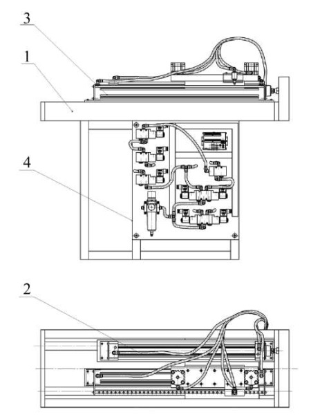
Fig. 1. Assembly drawing of the model stand:
1 — stand frame; 2 — loading pneumatic cylinder; 3 — automated long-stroke rodless pneumatic actuator in assembly; 4 — control panel
The stand, as a technical model of a pneumatic drive for experimental research, assembled on the basis of design documentation, is shown in Figure 2. To study the pneumatic and kinematic characteristics of the drive, an original control system was developed and applied, including a jet sensor and an external brake device [20].
In the course of the development of the experimental setup, a Camozzi 52G2P40A0400 rodless pneumatic cylinder with a working stroke of 400 mm and a piston diameter of 40 mm was mounted on the testing stand. The proposed original control system, developed as part of previous studies, was fixed on the movable carriage of this device [20].
This system included a jet sensor of an original design, consisting of two nozzle elements and a special rack with holes, as well as an external brake device, represented by two Camozzi 31F4A040A005 pneumatic cylinders with friction linings on the rods [8]. Friction linings of Argolon-TX material were selected due to their friction coefficient of 0.4 and linear wear, which is up to 5.5 μm/brake [13].
Additionally, a standard Camozzi 40M2L050A0400 pneumatic cylinder with a stroke length of 400 mm and a piston diameter of 50 mm was installed on the stand, which made it possible to simulate external loads on the drive. To verify the operability and accuracy of the jet sensor readings, a spillage method was used using a Camozzi MF4008-10-R-BV-A flow sensor located after the element under study, and two Camozzi SWCN-P10-P3-2 pressure sensors placed before and after this element. The tests of the jet sensor showed high reliability and stability of operation in various operating modes.
For the water drawing, a Camozzi MF4008-10-R-BV-A flow sensor was used, which had the following technical characteristics: analog output 0.5–4.5 V; measured value — volumetric flow rate; initial value of the flow measurement range — 0 l/min; final value of the flow measurement range — 10 l/min; accuracy (1.5+0.2∙FS/MV) %; operating pressure — 0–5 bar. Camozzi SWCN-P10-P3-2 pressure sensors were also used for the tests, which had the following technical characteristics: maximum measurement pressure — 10 bar; minimum measurement pressure — 1 bar; measurement pressure drop — 0.01 bar; maximum error — no more than 2.01%; scaling factor — 1.543. Additionally, Camozzi M043R-12 pressure gauges were used to provide measurement accuracy and pressure control in various drive units. The experimental stand was equipped with a modern electronic control unit, which included a Giga Device GD32F103VET6 microcontroller. It was responsible for collecting and processing data from all sensors of the pneumatic system, as well as for controlling the pneumatic distributors. To improve the accuracy of the actuator positioning, an encoder of the New Hong OVW6-10-2HC model was used, which had the following technical parameters [21]: power supply — DC 5–12 V, 12–24 V; response frequency — 0–100 kHz; consumption current — 80 mA. All data from the pressure sensors and the encoder were recorded in the system using the Modbus protocol [22]. Information from all measuring devices was collected by a personal computer synchronized with the microcontroller via the W5500 interface.
The DD1 controller interacted with the system, generating control signals for electromagnetic relays via a Unisonic Technologies ULN2003 transistor unit. This provided precise and reliable control of the pneumatic distributor solenoids, as well as maintaining the specified operating parameters of the drive in various operating modes [23].

Fig. 2. Research complex:
1 — power subsystem; 2 — drive control devices; 3 — main pneumatic cylinder for long-stroke movements with a loader; 4 — control system in the form of a jet sensor and an external brake device; 5 — electrical subsystem; 6 — personal computer
Figure 3 shows the research complex appearance. The principle of its operation is described in [8, 20], etc. The control system of this complex consists of a contactless jet sensor and an external brake device.
The contactless jet sensor transmits information about the current position of the actuator of the pneumatic cylinder, switches the drive controls for its deceleration and precise stopping.
The external braking device performs the work of fixing the actuator of the pneumatic drive when it is out of operation and precisely stops at a given coordinate. Then the actuator switches to the positioning speed.
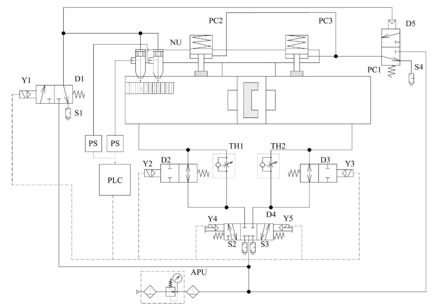
Fig. 3. Pneumatic scheme of the research complex:
PC1 — long-stroke pneumatic cylinder; PC2 and PC3 — external brake system pneumatic cylinders; NU — nozzle unit; D1 — sensor feed control distributor; D2; D3 — deceleration distributors; D4 — control distributor; D5 — external brake device control distributor; S1–S4 — pneumatic silencers; PS — pressure sensor; PLC — programmable logic controller; TH1 and TH2 — PC1 travel speed control throttles; APU — air preparation unit [4][6]
Experimental studies were conducted under the following conditions:
During the field experiment, the following were investigated:
Research Results. The graphs of the movement of the drive power elements, their speed, as well as the dependence of the air pressure in the drive pneumatic system, in comparison to the graphs of the same drive parameters obtained during the simulation, are presented in Figures 4–6.

Fig. 4. Graphs of change in time of speed and coordinates of displacement of the actuator of the studied pneumatic drive from time:
Xexp, Vexp — displacement and speed obtained experimentally, respectively;
Xsim, Vsim — displacement and speed obtained during the conducted mathematical modeling, respectively

Fig. 5. Graph of change in air pressure in the pressure and drain cavities of the studied pneumatic drive over time:
PAexp, PBexp — working gas pressure in the pressure and drain cavities, obtained experimentally, respectively;
PAsim, PBsim — gas pressure in the pressure and drain cavities, obtained during mathematical modeling, respectively
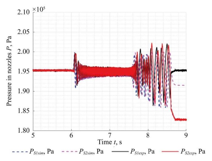
Fig. 6. Graph of the change in gas pressure in the nozzle units of a contactless jet sensor over time:
PS1exp, PS2exp — gas pressure in nozzle unit 1 and 2, obtained experimentally, respectively;
PS1sim, PS2sim — pressure in nozzle unit 1 and 2, obtained during mathematical modeling, respectively
The maximum discrepancy between the experimental data and the mathematical modeling data (Fig. 4–6) does not exceed 18%, which confirms the reliability of the research results [24].
The discrepancy between the research results was determined for all the data obtained (Fig. 4–6) using the following formula [25]:
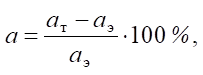 (1)
(1)
where aэ — data obtained during the experimental study (displacement, speed, pressure), aт — data obtained as a result of the theoretical study [26].
In Figures 7 and 8, the captions “Lexp” and “Lmod” denote oscillograms obtained as a result of full-scale and computational experiments, respectively.
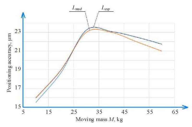
Fig. 7. Effect of mass M of the moving structure on the value of the positioning accuracy of the pneumatic drive:
Lexp — result obtained during a full-scale experiment,
Lmod — result obtained during mathematical modeling
Figure 7 shows the result of the study on the effect of mass M of the moving structure on the value of the positioning accuracy of the pneumatic cylinder.
The studies have shown that the positioning accuracy of the drive depends on the mass of the moving object. With an increase in mass from 10 to 30 kg, the positioning accuracy decreased by 1.47 times, and with an increase in mass to 60 kg, the accuracy worsened compared to a mass of 10 kg by 1.37 times.
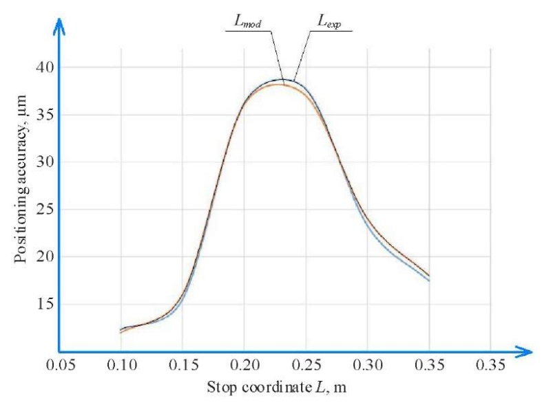
Fig. 8. Effect of working stroke length of the drive on value of its positioning accuracy:
Lexp — result obtained during a full-scale experiment,
Lmod — result obtained during mathematical modeling
Figure 8 shows the result of the study on the effect of the stop coordinate of the drive actuator on the accuracy of its positioning at the same maximum speed of movement. It was found that the accuracy of the drive positioning depends on the length of its working stroke to a complete stop (stop coordinates): when changing the stop coordinate from 0.1 m to 0.22 m, the positioning accuracy worsened by 3.2 times, and when changing the stop coordinate from 0.22 m to 0.35 m, the positioning accuracy increased by 2.2 times. This is due to the fact that during the operation of the drive, back pressure is created in the air cavity of the pneumatic cylinder when the piston approaches its extreme walls (and the closer to the wall, the greater the pressure) [27]. Back pressure also increases additionally during throttling due to the narrowing of the flow section of the channels of the holes intended for pumping and bleeding gas [28]. The narrowing of the flow sections of the channels causes the deceleration of gas flows [29]. This is observed when the actuator of the drive is moved at the positioning speed [30].
Discussion. The conducted experimental studies allowed obtaining good results in the development of long-stroke pneumatic drives. Successful verification of the mathematical model confirmed the correctness of the theoretical studies carried out in previous works [8][19].
The obtained positioning accuracy of the drive is 77 µm at a distance of over three meters. This figure significantly exceeds similar results presented in [13][15], which demonstrates high potential of the developed design, since the economic efficiency of the proposed solution is due to the absence of an electronic component base in the control system [31]. This not only reduces initial production costs, but also significantly simplifies maintenance of the drive during operation [32]. Comparative analysis with existing developments [2][13] confirms the superiority of the developed system in terms of cost criteria.
Conclusion. The main research results are as follows:
The conducted studies confirmed the efficiency of the developed solutions for long-stroke rodless pneumatic actuators.
The practical significance of the study is validated by the possibility of using the obtained results in the creation of high-precision long-stroke mechanisms in various industries [33]. The developed design can be used in automated production lines, robotic complexes, and other areas where precise positioning over significant distances is required.
Promising areas for further research include optimizing the parameters of the control system to obtain even higher positioning accuracy, as well as developing calculation methods for positioning long-stroke pneumatic drives.
1. Hongwei Zhu, Zhiwen Wang, Hu Wang, Zecheng Zhao, Wei Xiong. Leakage Fault Diagnosis of Two Parallel Cylinders in Pneumatic System with a Minimal Number of Sensors. Electronics. 2023;12(15):3261. https://doi.org/10.3390/electronics12153261
2. Rakulenko SV. Hydraulic Drive of Dependent Tool Advance (Using a Mobile Drilling Machine). Cand.Sci. (Engineering) diss. Rostov-on-Don: DSTU; 2019. 165 p. (In Russ.)
3. Mosadegh B, Polygerinos P, Keplinger C, Wennstedt S, ShepherdRF, Gupta U, et al. Pneumatic Networks for Soft Robotics that Actuate Rapidly. Advanced Functional Materials. 2014;24(15):2163–2170. https://doi.org/10.1002/adfm.201303288
4. Thanh Nguyen Truong, Anh Tuan Vo, Hee-Jun Kang. A Backstepping Global Fast Terminal Sliding Mode Control for Trajectory Tracking Control of Industrial Robotic Manipulators. IEEE Access. 2021;9:31921-31931. https://doi.org/10.1109/ACCESS.2021.3060115
5. Yilmaz BM, Tatlicioglu E, Savran A, Alci M. Self-Adjusting Fuzzy Logic Based Control of Robot Manipulators in Task Space. IEEE Transactions on Industrial Electronics. 2021;69:1620–1629. https://doi.org/10.1109/TIE.2021.3063970
6. Jihong Wang, Tim Gordon. Energy Optimal Control of Servo-Pneumatic Cylinders through Nonlinear Static Feedback Linearization. Journal of Dynamic Systems, Measurement, and Control. 2012;134(5):051005. https://doi.org/10.1115/1.4006084
7. Fracczak L, Nowak M, Koter K. Flexible Push Pneumatic Actuator with High Elongation. Sensors and Actuators A: Physical. 2021;321:112578. https://doi.org/10.1016/j.sna.2021.112578
8. Korotych DA, Sidorenko VS, Prikhodko SP. Investigation of Dynamic Characteristics of an Automated Position Long-Stroke Pneumatic Actuator of Fabrication System. Advanced Engineering Research (Rostov-on-Don). 2023;23(3):283–295. https://doi.org/10.23947/2687-1653-2023-23-3-283-295
9. Kurmyshev E, Jiménez M, Castaneda C. Experimental Study of Double-Acting Cylinder. Experimental Techniques. 2020;44(2):355–367. https://doi.org/10.1007/s40799-020-00359-8
10. Shilin DV. Increasing the Accuracy of Positioning the Carriage of a Rodless Pneumatic Unit. Cand.Sci. (Engineering) diss. Moscow: National Research University MPEI; 2016. 257 p. (In Russ.)
11. Urrea C, Kern J, Alvarado J. Design and Evaluation of a New Fuzzy Control Algorithm Applied to a Manipulator Robot. Applied Sciences. 2020;10(21):7482. https://doi.org/10.3390/app10217482
12. Behrouz Najjari, Masoud Barakati S, Ali Mohammadi, Mohammad Javad Fotuhi, Saeid Farahat, Mohammad Bostanian. Modelling and Controller Design of Electro-Pneumatic Actuator Based on PWM. International Journal of Robotics and Automation (IJRA). 2012;1(3):125–136.
13. Dao The Anh. High-Speed and High-Precision Positional Pneumatic Drive. Cand.Sci. (Engineering) diss. Rostovon-Don: DSTU; 2015. 206 p. (In Russ.)
14. Mobayen S, Mofid O, Din SU, Bartoszewicz A. Finite-Time Tracking Controller Design of Perturbed Robotic Manipulator Based on Adaptive Second Order Sliding Mode Control Method. IEEE Access. 2021;9:71159–71169. https://doi.org/10.1109/ACCESS.2021.3078760
15. Chaplygin EhI, D’jachkov EA, Gorjunov VA, Burkov JuG. Jet Device for Positioning of Reciprocal Motion Drive. RF Patent No. RU 2352973 C1. 2009. 6 p. URL: https://patents.s3.yandex.net/RU2352973C1_20090420.pdf (accessed: 20.06.2025).
16. Bae Hyo-Jeong, Jin Maolin, Suh Jinho, Lee Jun Young, Chang Pyung-Hun, Ahn Doo-sung. Control of Robot Manipulators Using Time-Delay Estimation and Fuzzy Logic Systems. Journal of Electrical Engineering and Technology. 2017;12(3):1271–1279. http://doi.org/10.5370/JEET.2017.12.3.1271
17. Obukhova EN, Popov AN. Synergetic Synthesis of Nonlinear Adaptive Control for Pneumatic Drives. In: Proc. IV International Conference on Control in Technical Systems (CTS). New York City: IEEE; 2021. P. 45–48. https://doi.org/10.1109/CTS53513.2021.9562786
18. Shenglin Mu, Seigo Goto, Satoru Shibata, Tomonori Yamamoto. Intelligent Position Control for Pneumatic Servo System Based on Predictive Fuzzy Control. Computers and Electrical Engineering. 2019;75:112–122. https://doi.org/10.1016/j.compeleceng.2019.02.016
19. Novoselov OG, Sabitov LS, Sibgatullin KE, Sibgatullin ES, Klyuev AV, Klyuev SV, et al. Method for Calculating the Strength of Massive Structural Elements in the General Case of Their Stress-Strain State (Parametric Equations of the Strength Surface). Construction Materials and Products. 2023;6(2):104–120. https://doi.org/10.58224/2618-7183-2023-6-2-104-120
20. Korotych DA, Sidorenko VS, Prikhodko SP. Jet Positional Pneumatic Drive System for Long-Stroke Positioning Coordinate Movements. RF Patent No. RU 2802568 C1. 2023. 10 p. URL: https://patentimages.storage.googleapis.com/f5/07/6c/7d26ddebc8dd07/RU2802568C1.pdf (accessed: 20.06.2025).
21. Božek P, Nikitin Yu. The Development of an Optimally-Tuned PID Control for the Actuator of a Transport Robot. Actuators. 2021;10(8):195. https://doi.org/10.3390/act10080195
22. Hailin Sun, Longlong Gao, Zhixin Zhao, Baoren Li. Finite-Time Active Disturbance Rejection Control for High-Pressure Pneumatic Servo System Subject to Matched and Mismatched Disturbances. In: Proc. 9th International Conference on Fluid Power and Mechatronics (FPM). New York City: IEEE; 2023. P. 1–7. https://doi.org/10.1109/FPM57590.2023.10565461
23. Weiping Hu, Rahim Mutlu, Weihua Li, Gursel Alici. A Structural Optimisation Method for a Soft Pneumatic Actuator. Robotics. 2018;7(2):24. https://doi.org/10.3390/robotics7020024
24. Gallyamov ShR, Starikov KV, Celischev VA. Experimental Study on the Characteristics of the FESTO Pneumatic Drive with a Proportional Flow Distributor. Vestnik UGATU. 2011;15(1):26–33. (In Russ.). URL: http://journal.ugatu.su/index.php/Vestnik/article/view/900 (accessed: 20.06.2025).
25. Novoselov OG, Sabitov LS, Sibgatullin KE, Sibgatullin ES, Klyuev AS, Klyuev SV, et al. Method for Calculating the Strength of Massive Structural Elements in the General Case of Their Stress-Strain State (Kinematic Method). Construction Materials and Products. 2023;6(3):5–17. https://doi.org/10.58224/2618-7183-2023-6-3-5-17
26. Vardhan Alok, Dasgupta Kaustubh, Mishra Santosh. Dynamic Analysis of a Closed-Circuit Hydraulic Drive System Used in the Rotary Head of Blasthole Drilling Machine Using MATLAB–Simulink Environment. Proceedings of the Institution of Mechanical Engineers, Part I: Journal of Systems and Control Engineering. 2018;233(6):702–719. https://doi.org/10.1177/0959651818808870
27. Abela K, Refalo P. Analysis of Pneumatic Parameters to Identify Leakages and Faults on the Demand Side of a Compressed Air System. Cleaner Engineering and Technology. 2022;6:100355. https://doi.org/10.1016/j.clet.2021.100355
28. The Anh Dao, Sidorenko VS, Dymochkin DD. Study on Positioning Accuracy of Automated Pneumatic Drive with an Outer Brake. Vestnik of Don State Technical University. 2015;15(4):46–53. https://doi.org/10.12737/16077
29. Grishchenko VI, Kilina MS, Dolgov GA. Mathematical Model of Hydraulic Shock Absorber with Feedback. In: Radionov AA, Gasiyarov VR (eds). Proc. 6th International Conference on Industrial Engineering. Lecture Notes in Mechanical Engineering. Cham: Springer; 2021. P.1262–1270. https://doi.org/10.1007/978-3-030-54817-9_147
30. Lemeshko M, Molev M, Golovin I. Hydraulic Technological Machines with Adaptive Drive Structure. MATEC Web of Conferences. 2018;224:02087. https://doi.org/10.1051/matecconf/201822402087
31. Ling Zhao, Shaomeng Gu, Jinhui Zhang, Sihang Li. Finite-Time Trajectory Tracking Control for Rodless Pneumatic Cylinder Systems with Disturbances. IEEE Transactions on Industrial Electronics. 2022;69(4):137–4147. https://doi.org/10.1109/TIE.2021.3071707
32. Haili Li, Jiantao Yao, Pan Zhou, Xinbo Chen, Yundou Xu, Yongsheng Zhao. High-Force Soft Pneumatic Actuators Based on Novel Casting Method for Robotic Applications. Sensors and Actuators A: Physical. 2020;306:111957. https://doi.org/10.1016/j.sna.2020.111957
33. Xiaoqian Chen, Xiang Zhang, Yiyong Huang, Lu Cao, Jinguo Liu. A Review of Soft Manipulator Research, Applications, and Opportunities. Journal of Field Robotics. 2022;39(3):281–311. https://doi.org/10.1002/rob.22051.
Daniil A. Korotych, Senior Lecturer of the Department of Hydraulics, Hydropneumoautomatics and Thermal Processes
1, Gagarin Sq., Rostov-on-Don, 344003
Scopus ID: 57222140590
ResearchGate IIU-3108-2023
The article experimentally validates a long-stroke rodless pneumatic actuator model with a maximum error of 18%. Full-scale tests were conducted using a unique control system based on a jet sensor and an external brake. It was shown that increasing the mass from 10 to 60 kg reduces positioning accuracy by 40%. A strong impact of the stop coordinate on accuracy was found due to backpressure in the drain cavity. The resulting solutions provided an accuracy of 77 µm over a distance of over three meters with a cost-effective control scheme.
Korotych D.A. Experimental Study on Positioning Accuracy of an Automated Long-Stroke Rodless Pneumatic Actuator. Advanced Engineering Research (Rostov-on-Don). 2025;25(3):197-207. https://doi.org/10.23947/2687-1653-2025-25-3-197-207. EDN: DFVDDQ


Advanced Engineering Research (Rostov-on-Don)
ISSN 2687-1653 (Online)
Contact with: Publisher / Editorial Office of the Journal
Publisher: Don State Technical University - DSTU, Rostov-on-Don, Russia - https://donstu.ru/en/
Editor-in-Chief: Alexey N. Beskopylny, Dr.Sci. (Eng.), Professor, Vice-Rector, Don State Technical University (Rostov-on-Don, Russia)
Don State Technical University
1, Gagarin Sq., Rostov-on-Don, 344003, Russia
tel.: +7 (863) 2738-372, e-mail: vestnik@donstu.ru
16+
Processing of personal data


