


Contents
Scroll to:
https://doi.org/10.23947/2687-1653-2025-25-4-2156
EDN: XOCYKW
Scroll to:
Introduction. In industry, the process of obtaining technological vacuum using ejectors that utilize the kinetic energy of a jet of compressed air is widely used. The selection of the required ejector model, as well as their number (when creating a field of ejectors), is performed proceeding from the compliance of the ejector characteristics with the key parameters of the designed process technology. One of the most important characteristics of an ejector, significantly affecting the overall performance of the vacuum system, is the evacuation time of the graduated (calibrated) container. However, in technical literature, this parameter is not specified for the maximum vacuum depth produced by the ejector, nor for the corresponding supply pressure, but for certain, less-defined parameters, referred to as optimal by ejector manufacturers. In such cases, it is impossible to accurately estimate the actual value of an important criterion. Therefore, the objective of this work is to experimentally determine the actual value of the vacuum time of a graduated (calibrated) vessel for various types of ejectors.
Materials and Methods. Experimental studies were performed on a stand specifically designed and manufactured by the authors, which made it possible to study various parameters of vacuum ejectors. In particular, the stand provided establishing the exact time of vacuuming a measuring vessel using ejectors with a nozzle diameter from 0.1 to 4.0 mm at a supply pressure value that induced the maximum vacuum depth for each model under study. The research was carried out using the most popular vacuum ejectors of the VEB, VEBL, VED and VEDL families manufactured by Camozzi at a pre-determined, precisely set input supply pressure for each ejector size. The actual values of the vacuum time at the highest vacuum depth for each ejector were experimentally determined.
Results. It has been established that the performance of VEB, VEBL, VEDL, and VED series ejectors differs from that stated in the manufacturer's catalog. The time required to reach maximum vacuum for each ejector exceeds the manufacturer's specifications by 25–40%, which impacts the performance of the vacuum system.
Discussion. The experimental data have shown that the actual values of the vacuum time of the measuring vessel differ from the values given in the catalogs of manufacturers of ejectors. This difference is explained by the fact that when conducting appropriate tests, manufacturers are guided not by the maximum vacuum depth created by the ejector, but by the vacuum depth created by a certain “optimal” (the wording of the ejector manufacturer) value of the supply pressure. In almost all the cases considered by us, this “optimal” supply pressure produced a vacuum, whose depth differed from the maximum. In this regard, it seems advisable to adjust the value of the inlet supply pressure to attain the maximum vacuum depth for each type of ejector.
Conclusions. The results of the obtained values of the vacuum creation time in one liter of volume at the maximum depth of the vacuum produced by the ejector provide a more accurate selection of vacuum ejectors depending on the required process tasks, ensure the greatest efficiency and cost-effectiveness of automated vacuum systems. The research results can be used by all ejector manufacturers to adjust their basic catalogs and appropriate recommendations for the use of these products. Further research will be conducted to study the accuracy of the geometric shapes of the surface of the ejector channel, the purity of processing, and their production technology, which affect the passage of air flow.
Savchuk S.I., Umerov E.D. Investigation of the Actual Value of the Vacuum Time of a Measuring Vessel by Ejector. Advanced Engineering Research (Rostov-on-Don). 2025;25(4):300-310. https://doi.org/10.23947/2687-1653-2025-25-4-2156. EDN: XOCYKW
Introduction. Industrial development, continuous improvement of processing, and the introduction of innovations in production bring about the ever-growing use of vacuum for moving parts by robots and manipulators in assembly areas, conveyor lines, metal spraying in a vacuum environment, etc. Moving and positioning complex-shaped parts, especially those such as foil or paper, is not possible without the use of vacuum suction cups.
The key parameter of a vacuum ejector is the supply pressure. Its optimal value provides a deep vacuum, which creates the conditions for attaining maximum efficiency. This provides high performance of the vacuum suction cup, a key element of the vacuum system, while minimizing energy costs.
In [1], a group of authors examined vacuum ejectors with various design features. A special-purpose vacuum stand was used for the experiments, measuring the magnitude of the generated vacuum as a function of the feed pressure at the inlet. It was found that the recommended feed pressure values provided in the ejector manufacturers' catalogs differed from the actual values obtained experimentally.
Typically, the supply pressure values recommended by ejector manufacturers do not allow for the full utilization of the ejectors they manufacture. That is, the “optimal” supply pressure values recommended in catalogs do not provide the maximum vacuum depth that each ejector in question can create. This reduces the device performance and, consequently, the efficiency of its actuator — the suction cup. The vacuum depth created by the ejector impacts significantly the cycle time. The deeper the vacuum created by the ejector, the shorter the suction cup response time, and the faster the vacuum-equipped section operates. This discovery is the occasion for further experimental research to determine the time it takes to create vacuums of varying depths in a liter of measuring vessel volume at a given supply pressure. This parameter can be considered as the ejector operating speed, reflecting the response speed of the ejector-suction cup system and directly affecting the operating time of this pair. It is also listed in the manufacturers' catalogs and directly impacts the operation of the vacuum suction cup and the guaranteed holding force.
It should be noted that the experiments to determine the vacuum time of the measuring vessel were carried out at a pre-determined supply pressure value [1], which provided the maximum vacuum depth produced by the ejector. This supply pressure value was set at the ejector inlet at the start of the experiment.
Currently, various types of ejectors, which are used in supersonic [2], steam [3], refrigeration [4] and other systems, are known. There are also two-stage ejectors used in hydrodynamics [5] and cooling systems [6]. They allow for the dynamic pressure control, which increases the efficiency of the performance.
Previously conducted studies made it possible to develop an analytical method for predicting the air flow in a supersonic air ejector [7]. A theory about its speed was put forward, a numerical analysis of the ejector operation was made [8], the results of its performance were obtained experimentally [9], the effect of the primary nozzle deflection on the ejector performance was studied using computational fluid dynamics [10], the effect of the Mach wave on the formation of the boundary of the moving flow in the device was considered [11], a theory of flow mixing was formulated [12], etc.
There is a large amount of research that demonstrates the use of various types of both vacuum ejectors [13], and vacuum technology [14]. In [15], the authors disclosed the theoretical foundations of vacuum and their physical essence [16]. However, very little attention was paid to the practical possibilities of using vacuum.
In [17], the author examines the application features of compressed air in pneumatic elements. In [18], the results of experimental studies with improved characteristics of the ejector nozzle are presented. And in [19], the process of air flow modeling is described. However, the issues related to the study of the parameters of vacuum ejectors receive almost no attention in modern scientific and technical literature. Basically, information about their parameters is contained only in specialized publications, for example, in the catalogs of companies engaged in the production of vacuum equipment, such as Schmalz, Festo, Camozzi, SMC, and others.
Taking into account all of the above, the authors aimed at establishing the actual value of the vacuuming time of a measuring (calibrated) vessel for various types of ejectors through experimental research.
Materials and Methods. Previously, the authors studied vacuum ejectors at various inlet supply pressures [1], recording the vacuum depth reached. After establishing the maximum vacuum at a given supply pressure, the time it took to attain vacuum in a volume equal to one liter was measured. The data obtained can be used to optimize the vacuum system parameters and improve its performance.
A specifically designed stand [20] was used for the experimental studies. Its photograph is shown in Figure 1.
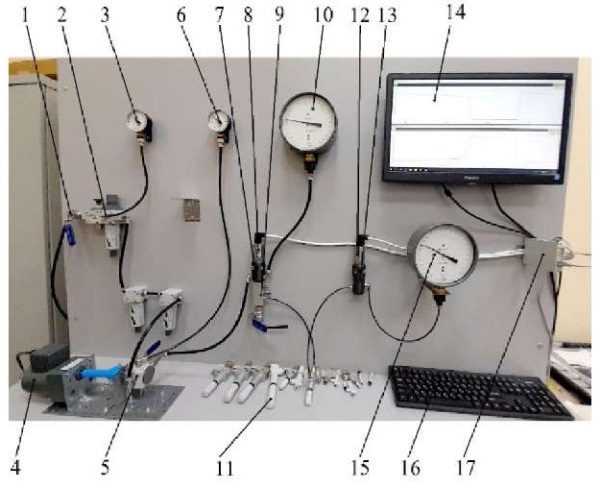
Fig. 1. Experimental stand:
1 — ball valve; 2 — air preparation unit; 3 — inlet control pressure gauge; 4 — electronically controlled motor gear; 5 — pressure regulator with shutoff valve; 6 — control pressure gauge; 7, 13 — pneumatic tees; 8 — MIDA-DI-15 excess pressure sensor; 9 — distribution block manifold; 10 — standard deformation pressure gauge; 11 — test vacuum ejector; 12 — MIDA-DA-15 absolute pressure sensor; 14 — monitor; 15 — standard deformation vacuum gauge (accuracy class 0.4); 16 — computer keyboard; 17 — MIDA-US-410 communication device
In the course of studies [1], the maximum vacuum depth created by the ejector was recorded depending on the inlet supply pressure. These parameters were subsequently used as reference values for a series of experiments aimed at establishing the time interval for creating a vacuum in a volume equal to one liter.
To conduct this part of the experiment, a special sealed vessel (Fig. 2) was designed and manufactured. It was equipped with fittings and shutoff valves to allow for the connection to the test stand and the ejectors being tested. The vessel volume was carefully measured with certified measuring instruments and found to be 1000.03 ml.
Before each experiment, the input supply pressure for all ejectors was set to provide the maximum vacuum depth. The value of this pressure corresponded to the experimental data given in [1] and was set using the control pressure gauge 10 and the pressure sensor 8 (Fig. 1).
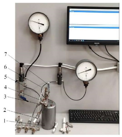
Fig. 2. Measuring vessel:
1 — measuring vessel; 2 — vacuum ejector under test; 3 — ball valve; 4 — ejector vacuum line; 5 — ejector inlet pressure line; 6 — vessel vacuum line; 7 — shutoff ball valve
Measuring vessel 1 can be linked with any ejectors that are connected to the process equipment through PVC tubing with a diameter of 4 to 10 mm. Ejectors 2 under study are connected to the distribution manifold 8 via the inlet supply pressure line 5 (Fig. 1). The ejectors under study are connected to the shutoff valve 7 installed directly on measuring vessel 1 via the vacuum line 4. Measuring vessel 1 is connected via the vacuum line 6 to tee 13 (Fig. 1). Air valve 3 connects the measuring vessel to the atmosphere.
The experiment was conducted in the following order. Air valve 3 and shutoff valve 7 were closed. The ejector under study was then connected to a specialized test stand, where the supply pressure at the inlet was adjusted to a value that provided the greatest vacuum depth. Shutoff valve 7 was then opened, and the emptying of the measuring vessel started. A sign of complete emptying was the achievement of a stable vacuum depth, which was recorded by vacuum gauge 12 and absolute pressure sensor 15 (Fig. 1). After recording the instrument readings, the measuring vessel was refilled with air at atmospheric pressure, for which purpose shutoff valve 7 was closed and air valve 3 was opened.
Research Results. Figures 3–6 show diagrams of the dependence of the time to reach the vacuum depth in one liter of volume on the supply pressure for different types of ejectors. Tables 1–4 present the supply pressure and vacuum depth data obtained experimentally and provided in the manufacturer's catalog.
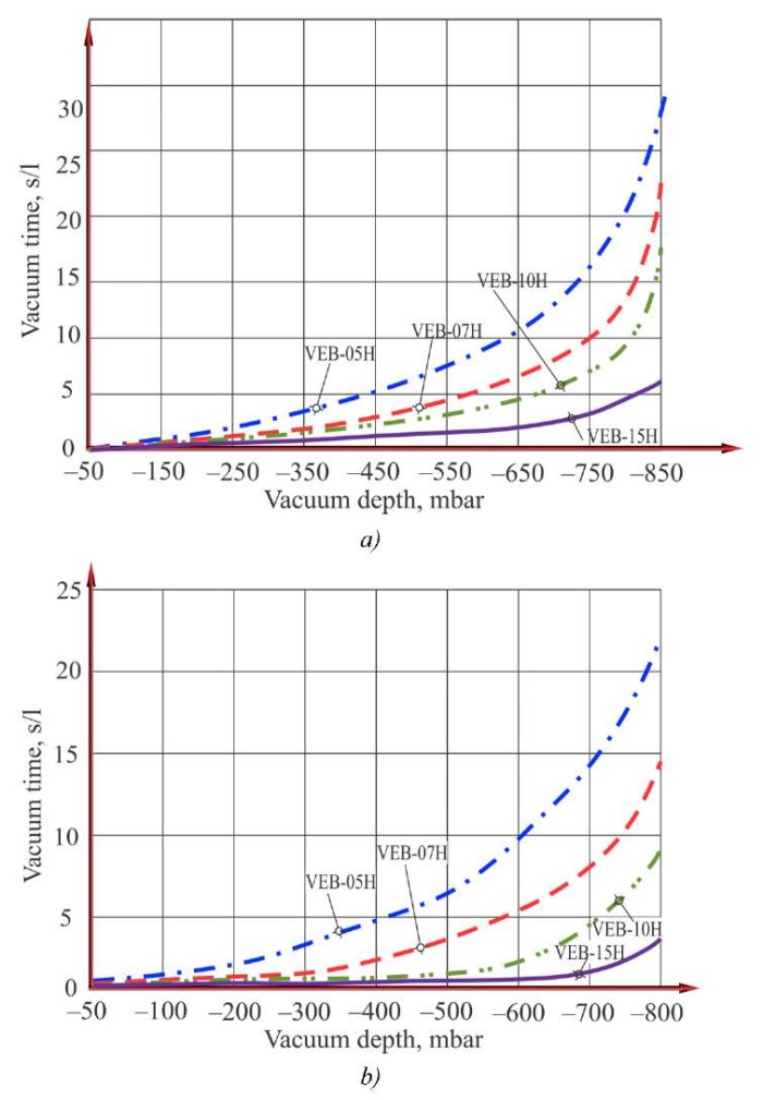
Fig. 3. Vacuum creation time diagrams for one liter of volume for VEB series ejectors:
a — according to the authors' data; b — according to the company catalog
Figure 3 shows the diagrams of the dependence of the vacuum time of the measuring vessel for the VEB series ejectors, obtained by the authors (left) and contained in the manufacturer's catalog (right). Table 1 shows the supply pressure values at which the optimal vacuum depth values were obtained, as well as the manufacturer's recommended values for the optimal supply pressure and the expected vacuum depth at these values.
Table 1
Comparative Data on Supply Pressure and Vacuum Level for VEB Series Ejectors
|
Ejector model |
Manufacturer's data |
Experimental data |
||||
|
Ø nozzle, mm |
Vacuum depth, mbar |
Optimal working pressure, bar |
Maximum vacuum depth, mbar |
Feed pressure, bar |
Vacuum depth at recommended pressure, mbar |
|
|
VEB-05H |
0.5 |
182 |
4.5 |
96 |
4.73 |
115 |
|
VEB-07H |
0.7 |
152 |
4.5 |
108 |
4.07 |
115 |
|
VEB-10H |
1.0 |
152 |
5.0 |
132 |
4.90 |
133 |
|
VEB-15H |
1.5 |
152 |
4.5 |
109 |
4.75 |
145 |
The analysis of the diagrams and tables shows that the curve patterns and measuring vessel vacuum time for the VEB series ejectors are similar to those provided in the manufacturer's catalog. It has been established that the ejectors reach significantly greater vacuum depth at lower supply pressures. This means that the desired effect is attained at lower supply pressures than those recommended by the ejector manufacturer, which is undoubtedly safer and more efficient. Moreover, even with a feed pressure at the ejector inlet equal to the manufacturer's recommended “optimal” pressure, the vacuum depth is still greater than stated in the manufacturer's catalog (Table 1). The authors have also found that for the VEB-15H ejector, even when reaching maximum vacuum depth, the time required to empty the measuring vessel is 70% longer than stated in the manufacturer's catalog.
Figure 4 shows the diagrams of the dependence of the vacuum time of the measuring vessel for the VEBL series ejectors, obtained by the authors (left) and given in the manufacturer's catalog (right). Table 2 presents the supply pressure values at which the authors obtained the best (optimal) vacuum depth values. It also lists the manufacturers' recommended optimal supply pressure values and the expected vacuum depth at these values.
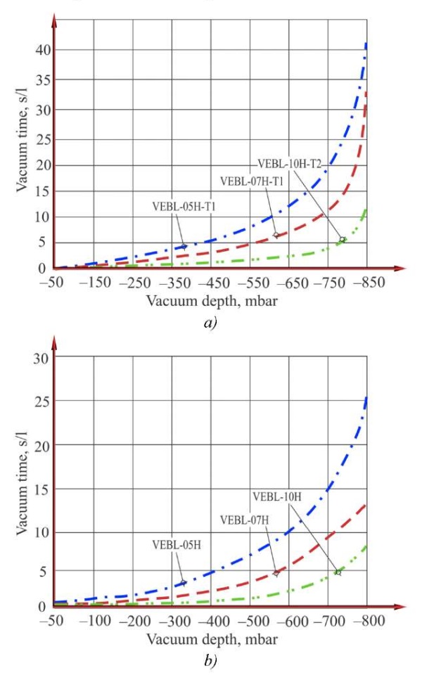
Fig. 4. Vacuum creation time diagrams for one liter of volume for the VEBL series ejectors:
a — according to the authors' data; b — according to the company's catalogue
Table 2
Comparative Data on Supply Pressure and Vacuum Level for VEBL Series Ejectors
|
Ejector model |
Manufacturer's data |
Experimental data |
||||
|
Ø nozzle, mm |
Vacuum depth, mbar |
Optimal working pressure, bar |
Maximum vacuum depthl, mbar |
Feed pressure, bar |
Vacuum depth at recommended pressure, mbar |
|
|
VEBL-05H-T1 |
0.5 |
160 |
4.5 |
121 |
4.20 |
127 |
|
VEBL-07H-T1 |
0.7 |
150 |
4.5 |
133 |
4.10 |
142 |
The diagrams and table show that the curves and measuring vessel evacuation times for the VEBL series ejectors are similar to those provided in the manufacturer's catalog. However, since the ejectors reach significantly greater vacuum depths at lower supply pressures, the desired effect is attained at lower supply pressures than recommended by the ejector manufacturer, which is undoubtedly safer and more efficient. Moreover, even if the feed pressure at the ejector inlet is set to the manufacturer's recommended “optimal” pressure, the vacuum depth is still greater than that specified in the manufacturer's catalog (Table 2). The authors have also found that for the VEBL-10H ejector, even when the maximum vacuum depth is reached, the time required to empty the measuring tank is 40% longer than that specified in the manufacturer's catalog.
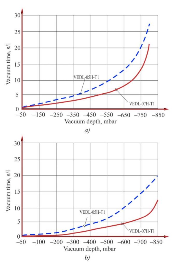
Fig. 5. Vacuum creation time diagrams for one liter of volume for the VEBL series ejectors:
a — according to the authors' data; b — according to the company's catalogue
Figure 5 shows the diagrams of the dependence of the vacuum time of the measuring vessel for the VEDL series ejectors, obtained by the authors (left) and given in the manufacturer's catalog (right). Table 3 presents the supply pressure values at which the best (optimal) vacuum depth values were obtained, as well as the recommended optimal supply pressure values by the manufacturers, and the expected vacuum depth at these values.
Table 3
Comparative Data on Supply Pressure and Vacuum Level for VEBL Series Ejectors
|
Ejector model |
Manufacturer's data |
Experimental data |
||||
|
Ø nozzle, mm |
Vacuum depth, mbar |
Optimal working pressure, bar |
Maximum vacuum depthl, mbar |
Feed pressure, bar |
Vacuum depth at recommended pressure, mbar |
|
|
VEDL-05H-T1 |
0.5 |
170 |
4.5 |
130 |
4.00 |
142 |
|
VEDL-07H-T1 |
0.7 |
150 |
4.5 |
207 |
3.40 |
256 |
Judging by the diagrams and data in the table, the nature of the curves and the vacuum time of the measuring vessel for the VEDL series ejectors are similar to the data given in the manufacturer’s catalog.
The authors have found that the performance data for the VEDL series ejectors differs from that provided in the manufacturer's catalog. Specifically, for the VEDL-05N-T1 ejector, the time required to reach maximum emptying of the measuring vessel (–800 mbar) was 27 seconds (the time provided in the catalog is 19 seconds), which is 40% longer. Similarly, for the VEDL-07N-T1 ejector, the time required to attain maximum emptying of the measuring vessel (–800 mbar) was 20 seconds (the time provided in the catalog is 11 seconds), which is 81% longer.
Figure 6 shows the diagrams of the dependence of the vacuum time of the measuring vessel for the VED series ejectors, obtained by the authors (left) and given in the manufacturer's catalog (right). Table 4 shows the supply pressure values at which the best vacuum depth values were reached, as well as the manufacturer's recommended optimal supply pressure values and the expected vacuum depth at these values.
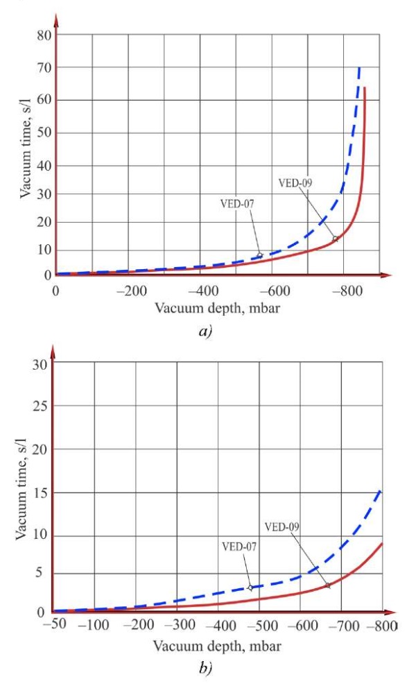
Fig. 6. Vacuum creation time diagrams for one liter of volume for VEB series ejectors:
a — according to the authors' data; b — according to the company catalog
Table 4
Comparative Data on Supply Pressure and Vacuum Level for VEB Series Ejectors
|
Ejector model |
Manufacturer's data |
Experimental data |
||||
|
Ø nozzle, mm |
Vacuum depth, mbar |
Optimal working pressure, bar |
Maximum vacuum depthl, mbar |
Feed pressure, bar |
Vacuum depth at recommended pressure, mbar |
|
|
VED-07 |
0.7 |
101 |
5.0 |
405 |
4.70 |
409 |
|
VED-09 |
0.9 |
111 |
5.0 |
120 |
4.20 |
133 |
The analysis of the experimental data shows that the nature of the curves and the vacuum time of the measuring vessel for the VED series ejectors are similar to the curves given in the manufacturer’s catalog.
The authors also found that the performance of the VED series ejectors differed from that listed in the manufacturer's catalog. Specifically, for the VED-07 ejector, the time required to reach maximum emptying of the measuring vessel (–800 mbar) was 20 seconds (versus 15 seconds listed in the catalog), a 33% increase. For the VED-09 ejector, the time required to achieve maximum emptying of the measuring vessel (–800 mbar) was 10 seconds (versus 8 seconds listed in the catalog), a 25% increase.
Discussion. The experimentally obtained data on the actual time of vacuuming the measuring vessel by ejectors differ from the data given in the catalogs of the manufacturers. A positive aspect here is that the vacuum depth values stated by the manufacturer are reached at much lower supply pressures than those presented in the catalogs. Furthermore, the actual vacuum depth is significantly more efficient than described by the manufacturer. However, the actual time to empty the measuring vessel turned out to be longer than the manufacturers stated in their catalogs. Sometimes, this time was significantly exceeded.
This fact can be of vital importance for designing the process cycle of equipment operation, as it reflects the actual capabilities of certain types of ejectors in terms of vacuum creation rates. This emphasizes the significance of such a parameter as the vacuum time of the measuring vessel when selecting ejectors. This property is critically important for calculating the required amount of time when constructing an ejector field to maintain the required vacuum depth.
Conclusion. The analysis of the data obtained during the experiment shows that the nature of the curves during evacuation of the measuring vessel for ejectors of the VEB, VEBL, VEDL and VED series is similar to the data given in the manufacturer’s catalog. However, the time required for each of the ejectors to reach maximum vacuum depth differs. It exceeds the time specified by the manufacturers by 25–40%. This fact affects the performance of both the ejector itself and the vacuum system as a whole. In this regard, when solving process tasks in production, it is required to carefully select vacuum ejectors in order to provide the greatest efficiency and cost-effectiveness of automated vacuum systems.
The research results can be used as recommendations for the utilization of ejectors and for adjusting catalogs of manufacturing companies.
Further research in this area will be aimed at studying the accuracy of the geometric shapes of the surface of the ejector channel, the cleanliness of processing and their production technology, which affect the passage of air flow.
1. Savchuk SI, Umerov ED, Abdulgazis AU. Investigation of the Optimal Vacuum Depth Created by the Ejector Depending on the Value of the Supply Pressure. Advanced Engineering Research (Rostov-on-Don). 2025;25(1):43–51. https://doi.org/10.23947/2687-1653-2025-25-1-43-51
2. Xinyue Hao, Jiwei Yan, Neng Gao, Volovyk O, Yifan Zhou, Guangming Chen. Experimental Investigation of an Improved Ejector with Optimal Flow Profile. Case Studies in Thermal Engineering. 2023;47:103089. https://doi.org/10.1016/j.csite.2023.103089
3. Yongzhi Tang, Zhongliang Liu, Can Shi, Yanxia Li. A Novel Steam Ejector with Pressure Regulation to Optimize the Entrained Flow Passage for Performance Improvement in MED-TVC Desalination System. Energy Conversion and Management. 2018;172(8):237–247. https://doi.org/10.1016/j.enconman.2018.07.022
4. Tashtoush BM, Al-Nimr MA, Khasawneh MA. A Comprehensive Review of Ejector Design, Performance, and Applications. Applied Energy. 2019;240:138–172. https://doi.org/10.1016/j.apenergy.2019.01.185
5. Elhub B, Mat S, Sopian K, Elbreki AM, Ruslan MH, Ammar AA. Performance Evaluation and Parametric Studies on Variable Nozzle Ejector Using R134A. Case Studies in Thermal Engineering. 2018;12:258–270. https://doi.org/10.1016/j.csite.2018.04.006
6. Tao Hai, Masood Ashraf Ali, Dhahad HA, Alizadeh A, Sharma K, Sattam Fahad Almojil, et al. A Novel BiEvaporator Cooling System via Integration of Absorption Refrigeration Cycle for Waste Energy Recovery from an Ejector-Expansion Trans-Critical CO2 (EETRCC) Cycle: Proposal and Optimization with Environmental Considerations. Sustainable Energy Technologies and Assessments. 2023;57(12):103118. http://doi.org/10.1016/j.seta.2023.103118
7. Arvind Kumar, Surendra Yadav, Virendra Kumar, Abhishek Kulkarni. A Comprehensive Exploration of Ejector Design, Operational Factors, Performance Metrics, and Practical Applications. Journal of the Brazilian Society of Mechanical Sciences and Engineering. 2024;46:39. https://doi.org/10.1007/s40430-023-04618-8
8. Mazzelli F, Little AB, Garimella S, Bartosiewicz Y. Computational and Experimental Analysis of Supersonic Air Ejector: Turbulence Modeling and Assessment of 3D Effects. International Journal of Heat and Fluid Flow. 2015;56:305–316. https://doi.org/10.1016/j.ijheatfluidflow.2015.08.003
9. Yin-Hai Zhu, Yanzhong Li. Novel Ejector Model for Performance Evaluation on Both Dry and Wet Vapors Ejectors. International Journal of Refrigeration. 2009;32(1):21–31. https://doi.org/10.1016/j.ijrefrig.2008.08.003
10. Yuyan Hou, Fengwu Chen, Sheng Zhang, Weixiong Chen, Jiantao Zheng, Daotong Chong, et al. Numerical Simulation Study on the Influence of Primary Nozzle Deviation on the Steam Ejector Performance. International Journal of Thermal Sciences. 2022;17:107633. https://doi.org/10.1016/j.ijthermalsci.2022.107633
11. Zuozhou Chen, Chaobin Dang, Eiji Hihara. Investigations on Driving Flow Expansion Characteristics inside Ejectors. International Journal of Heat and Mass Transfer. 2015;108(A):490–500. https://doi.org/10.1016/j.ijheatmasstransfer.2016.12.040
12. Sunghoon Baek, Seungbin Ko, Simon Song, Sungmin Ryu. Numerical Study of High-Speed Two-Phase Ejector Performance with R134a Refrigerant. International Journal of Heat and Mass Transfer. 2018;126(A):1071–1082. http://doi.org/10.1016/j.ijheatmasstransfer.2018.05.053
13. Levchenko DA, Meleychuk SS, Arseniev VM. Substantive Provision of a Method of Calculation Vortical Ejector Stage of the Vacuum Unit. Procedia Engineering. 2012;39:28–34. https://doi.org/10.1016/j.proeng.2012.07.004
14. Kumar V, Sachdeva G. 1-D Model for Finding Geometry of a Single Phase Ejector. Energy. 2018;165(A):75–92. https://doi.org/10.1016/j.energy.2018.09.071
15. Arun Kumar R, Rajesh G. Physics of Vacuum Generation in Zero-Secondary Flow Ejectors. Physics of Fluids. 2018;30(6):066102. https://doi.org/10.1063/1.5030073
16. Karthick SK, Rao SM,Jagadeesh G, Reddy KP. Parametric Experimental Studies on Mixing Characteristics within a Low Area Ratio Rectangular Supersonic Gaseous Ejector. Physics of Fluids. 2016;28(7):076101. https://doi.org/10.1063/1.4954669
17. Гессе С. Сжатый воздух как носитель энергии. Москва: Фесто; 2004. 128 с. Hesse S. Compressed Air as an Energy Carrier. Moscow: Festo; 2004. 128 p. (In Russ.)
18. Goodman N, Leege BJ, Johnson PE. An Improved de Laval Nozzle Experiment. International Journal of Mechanical Engineering Education. 2021;50(2):513–537. https://doi.org/10.1177/03064190211034165
19. Moukalled F, Mangani L, Darwish M. The Finite Volume Method in Computational Fluid Dynamics. Berlin, Heidelberg: Springer; 2016. 113 p. https://doi.org/10.1007/978-3-319-16874-6
20. Savchuk SI, Umerov ED, Abdulgazis UA. Stand for Assessing the Depth of Vacuum Supplied to Specialized Suction Cups Used in Technological Processes of Service during Operation and Production of Cars. Scientific Notes of the Crimean Engineering and Pedagogical University. 2023;82(4):225–230. https://doi.org/10.34771/UZCEPU.2023.82.4.043.
Sergey I. Savchuk, Cand.Sci. (Eng.), Associate Professor of the Department of Automobile Transport and Traffic Management
8, Uchebnyi Lane, Simferopol, 295015, Republic of Crimea
Ervin D. Umerov, Cand.Sci. (Eng.), Associate Professor of the Department of Automobile Transport and Traffic Management
8, Uchebnyi Lane, Simferopol, 295015, Republic of Crimea
Scopus Author ID: 57197734041
The study has obtained actual values for vessel evacuation time. The time it takes to create maximum vacuum depth for ejectors is measured for the first time. It is shown that actual values exceed catalog values by one-third. A method for selecting supply pressure to reach maximum vacuum is proposed. The results enable more accurate selection of ejectors for specific process applications. The data can be used in the design and modernization of vacuum systems.
Savchuk S.I., Umerov E.D. Investigation of the Actual Value of the Vacuum Time of a Measuring Vessel by Ejector. Advanced Engineering Research (Rostov-on-Don). 2025;25(4):300-310. https://doi.org/10.23947/2687-1653-2025-25-4-2156. EDN: XOCYKW


Advanced Engineering Research (Rostov-on-Don)
ISSN 2687-1653 (Online)
Contact with: Publisher / Editorial Office of the Journal
Publisher: Don State Technical University - DSTU, Rostov-on-Don, Russia - https://donstu.ru/en/
Editor-in-Chief: Alexey N. Beskopylny, Dr.Sci. (Eng.), Professor, Vice-Rector, Don State Technical University (Rostov-on-Don, Russia)
Don State Technical University
1, Gagarin Sq., Rostov-on-Don, 344003, Russia
tel.: +7 (863) 2738-372, e-mail: vestnik@donstu.ru
16+
Processing of personal data


