


Contents
Scroll to:
https://doi.org/10.23947/2687-1653-2023-23-1-41-54
Scroll to:
Introduction. Data on the occurrence of initial failures obtained through testing on standard samples cannot always be extrapolated to real welded joints and structures. This is due to the difference between the concentrators in the joints, because after welding there is a significant structural and mechanical heterogeneity of the heat-affected and stress concentrator zone. Extended, deep concentrators are considered as crack-like defects, at whose vertices a volumetric, multiaxial stress state is formed. The paper addresses the issue of constructing critical diagrams of the onset of the limiting state at the concentrator vertex, which depends on the level of external load and the theoretical concentration coefficient.
Materials and Methods. Analytical methods were used to study the stress state. The literature on the topic was analyzed. The features of proven physical models and patterns of behavior of materials were taken into account. The characteristics of steel alloys were taken from open sources and summarized in a tabulated form. Nonlinear equations were solved in Matlab applications. The diagrams constructed by the authors enable to track the correlation of the dangerous level of the theoretical stress concentration factor and the level of external load. Curve Fitting Toolbox Matlab was used to design the graphic part of the work.
Results. The characteristic of damage from stress concentrators in welded joints was given. The crack propagation in the fusion zone was shown. The conditions stimulating and inhibiting destruction were indicated. The theoretical stress concentration factor α𝑇 was specified. It was shown how this indicator depended on the width, the height of the seam and the thickness of the welded part. Acute stress concentrators with theoretical concentration factor αт= 5…14 and more were studied. For this case, an approximating formula was given that took into account the maximum stress in the concentrator in the first half cycle, the initial deformation, and the load ratio. Through those elements, an indicator of an increase in maximum stresses was set depending on the number of loading cycles. The flow condition, the stress state, and the overvoltage factor, which took into account the increase in the first principal voltage for a combined stress state, were analytically shown. A model of the critical state at the apex of an acute stress macro concentrator was described. It was presented as the dependence of the relative stresses of the initiation of destruction σн𝑏𝑐/σ0,2 on the concentrator. Possible variations of this model were analyzed. The dependences of relative values σ𝐻𝑏𝑐⁄σ0,2 on the theoretical concentration factor α𝑇𝑏𝑐=α𝑇 were presented. To check the physical adequacy of this model, graphs were constructed that reflected changes in the relative stress of the external load at a critical state at the stress concentrator apex. The inevitability of bifurcation as a result of the studied processes was validated. Two directions of further development of events were indicated: brittle destruction and loss of stability of the stressed state with the transition to an increase in plastic deformations. The moment of bifurcation was defined as a critical state in the focus of the concentrator.
Discussion and Conclusion. The analysis and calculations performed within the framework of the presented scientific work enabled, in particular, to draw conclusions about the role of key factors of the processes under study. It was established, for example, that the operation of a steel alloy at a high theoretical stress concentration factor depended on the characteristics of the stress state. In a rigid state, it was possible to inhibit shear deformation and the onset of the limiting state at a lower value of the theoretical stress concentration factor. With the usual strength of steel (in comparison to high), a greater impact of the volume of the stress state on the value of the theoretical stress concentration factor was recorded. The probability of failure depended on the resistance of the material to the growth of a macrocrack. In future research, it is possible to refine analytical models and results, evaluate effective stress concentration factors.
Molokov K.А., Novikov V.V., Dabalez M. Evaluation of the Occurrence of Initial Failures from Stress Concentrators in Welded Joints and Structural Elements. Advanced Engineering Research (Rostov-on-Don). 2023;23(1):41-54. https://doi.org/10.23947/2687-1653-2023-23-1-41-54
Introduction. Static and fatigue strength is reduced due to defects in welded joints. These can be:
In the latter case, the determining factors will be:
Under cyclic loads, cracks often occur and develop in welded joints, provoked by stress concentrators [2]. The risk also depends on how close the stress state of the welded joint with the concentrator is to the occurrence of a macrocrack and its spread at operating σ𝐻 and cyclic loads σ−1. Obviously, the latter depends significantly on the size, shape of the macrodefect and the stress state at its top. For example, an oblong and narrow macro stress concentrator is more dangerous than a rounded one. Probably, a crack is immediately formed at its top, and together with it, the initial concentrator will represent one long macrocrack [3]. The size of such a “total” macrocrack may be critical, which will reduce the static strength [4]. It depends on its length and mechanical characteristics of the material at the top of the initial concentrator.
The study objective is to develop an analytical model for assessing the dangerous level of stress concentration. The case in hand is about the formation of a crack in the top of the concentrator, a sharp decrease in the bearing capacity of welded joints and structural parts.
Materials and Methods. Scientific research within the framework of the stated topic was based on known physical models and patterns of behavior of materials. The theoretical and applied literature was analyzed. Illustrative and reference materials were extracted from the sources.
The stress state was studied by analytical methods. The relationship between the rigidity of the stress state and the value of the theoretical stress concentration factor was established. The results were presented in the form of diagrams. This visualization method made it possible to track the correlation of the dangerous level of external load and the theoretical stress concentration factor.
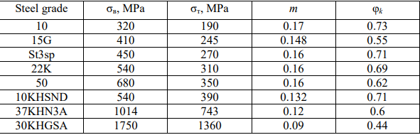
To check the results of calculations based on the physical adequacy of the authors’ model, dependency graphs for the critical state were constructed. The paper used information about widespread structural steels of ferrite-perlite class in the state of delivery (steel 10, 22K, 50, St3sp, 37KHN3A, 30KHGSA, etc.). Their mechanical characteristics were obtained from open sources1 and summarized in Table 1. The data was visualized in the Curve Fitting Toolbox MATLAB.
Table 1
Characteristics of steels
Mathematical apparatus was applied to derive formulas. When solving nonlinear equations, the MATLAB application software package was used.
Characteristics of damage from stress concentrators in welded joints. Since early 2000s, stress concentrations in welded joints and structures have been studied in relation to industrial tasks [2–3][5–9].
Figure 1 shows examples of destruction of welded joints due to stress concentration.
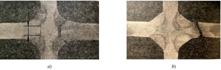
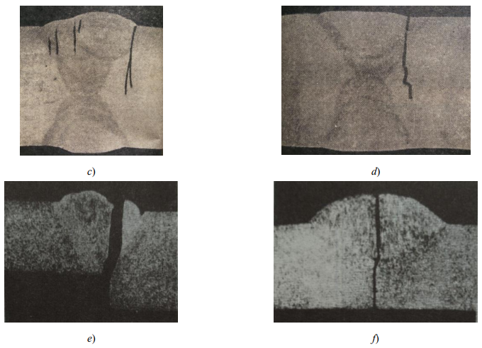
Fig. 1. Destruction of cross and butt joints2 from stress concentrators: a, f — from the incomplete fusion zone, square butt joint; b — from undercutting, V-weld; c — from a sharp transition in the fusion zone; d — undercut; e — from the concentrator formed by a step transition at the edge junction [10]
The destruction of cross joints with large non-fusion of the edges (indicated by arrows in Fig. 1a) is possible under the following loads:
In [5], the stress distribution for butt, corner, cross joints and intermittent connections of ship structures is analyzed. In butt and cross welded joints, the area of the base metal adjacent to the weld is of particular importance. This is the weakest cross-section that determines the strength of the joint at variable stresses. It should be noted that the welds are always quite long compared to the thickness of the metal and the stress concentrator (undercut in the butt or cross joint). This prevents a shift in the area of the concentrator and creates a biaxial, and more often a multiaxial stress state [11][12]. When considering the destruction of welds with concentrators (see Fig. 1 a, e, f), we take into account the concept of the occurrence of plastic deformation in the top region [5][7]. In addition, it should be noted that the concentrators are adjacent to the fusion zone, which, after welding, experiences longitudinal residual tensile stresses. They affect the degree of rigidity of the stress state in the concentrator focus [1][13–14]. All this prevents the passage of shear in the concentrator focus and can contribute to the occurrence of a minimal brittle macrocrack with a high theoretical stress concentration factor αт even from static load.
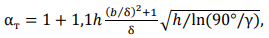
In [9], indicative failures from welded defects in large-diameter pipelines are described. It is established that with long-term operation (more than 20 years), fatigue cracks appear in the undercuts of longitudinal welded pipe joints. Cracks in undercuts in the fusion zone, as a rule, branch out and spread in two directions (fig. 2): one moves away from the fusion zone, the other develops along the fusion zone (along the weld). This indicates a strong impact of the mechanical, structural characteristics of the material3 and mechanochemical heterogeneity on the propagation of initial destruction [13][14]. On the other hand, the crack branching can complicate the process of further destruction and the transition of the crack into the main one.
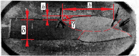
Fig. 2. Destruction in the pipe welded joint from the stress concentration in the fusion zone. Steel 14HGS. Single arrow shows fatigue cracks; double arrow — pipe burst edge; strokes — weld outlines. Here, b — weld width; h — weld height; δ — weldment thickness; γ — angle of transition from base metal to weld [9]
The theoretical stress concentration factor in the fusion zone can be determined from the formula that takes into account the concentration effect of a non-melting transition in this zone [5]:
 (1)
(1)
where γ = 𝐴[ 90 exp(−ρ⁄ρ0)+ 𝐵] — angle of transition from base metal to weld; ρ — radius of transition from base metal to weld; ρ0 = 1 mm; 𝐴 = 0.94 … 0.17; 𝐵 = 0.8; 𝑏 — weld width; ℎ — weld height; δ — weldment thickness (fig. 2).
However, this dependence does not take into account the changed mechanical characteristics of the material. In these zones, hardening structures are usually present, whose mechanical characteristics can differ significantly (up to 30 %) from the characteristics of the weld and the base metal.
It is possible to indirectly control crack formation and the stress state in the region of the top of the stress concentrator through the concentration factor of their intensity. Accordingly, when a sample fails due to fatigue, one macrocrack is formed at the concentrator top, and in a corrosive medium — a group (fig. 3).
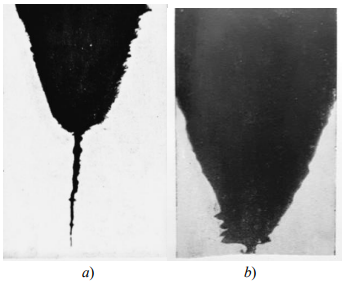
Fig. 3. Fatigue failure of steel 45 from a V-shaped stress concentrator: a — in air; b — in water — in a corrosive environment. An increase of 134 times4
After the formation of a group of macrocracks (fig. 3 b), the role of the macro-concentrator decreases, and further development of destruction can be suspended or inhibited. This was validated by experiments that indicated an increase in fatigue strength in samples with stress concentration in a corrosive environment5. Such a group of cracks loosens the material, changes the stress state above and below the surface at the top of the macro-concentrator, which prevents the formation of a leading crack that can develop further at a lower level of cyclic loads.
Consider the situation on the surface or in the thickness of metal in massive bodies under stresses σ𝐻 at infinity in a plane-stressed state. In this case, it is reasonable to use the Kolosov and Inglis’s solution for an elliptical shape concentrator:
 (2)
(2)
where ρ и σ𝑚𝑎𝑥 — radius of curvature and maximum component of stresses on the surface, respectively, at the top of the notch; 𝑎 — semi-major axis, or half of the longest area perpendicular to the direction of the external load field.
Dependence (2) is well consistent with engineering practice. In accordance with the accepted concept, the theoretical stress concentration factor at the notch is determined by the depth of the notch and the contour curvature radius at its top, but does not depend on the shape of the contour.
Due to the development of information technologies, the evaluation of the theoretical stress concentration factor presents no great difficulty. The results of calculations of stress and strain concentrations in elastic and elastoplastic formulation of the problem can be obtained through the CAE finite element analysis [16–18][12].
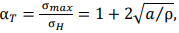
The experiments showed that at a certain stress concentration, external static load, and elastic-plastic stage of the material, an initial fracture crack appeared at the concentrator top at a certain distance from the surface. It rapidly propagated to an axis perpendicular to the direction of tension of the notched plates. The propagation is visible in the pictures (fig. 4). The process was fixed in the plates under a plane stress state and under a plane deformation. In the latter case, the appearance of a crack in the thickness of the metal under the surface was detected using an ultrasonic flaw detector.
Fig. 4. Initiation of a subsurface crack at the top of the concentrator under static tension: a — macrocrack initiation; b, c — size increase in depth and towards the surface; d — crack exit to the surface [19]
Thus, under the given conditions and a sufficiently acute stress concentrator, a zone of a multiaxial stress state was formed, in which the continuity violation was possible. There would be a higher level of the onset of fluidity, and the tensile strength in a weakened place due to the concentrator could increase to 20-60 % (it depends on the material) [11].
Stress concentration and stress state conditions. Consider rather sharp stress concentrators with theoretical concentration factor αт = 5 … 14 and more. As a rule, the defects mentioned above act as such concentrators. At the top of the concentrator, the stress state can be considered the same as in plane deformation. In [18], the results of the analytical solution and experimental data for sharp concentrators under plane deformation were presented, the region of admissible values [α𝑇] and the radius at the top [ρ] for steel 09G2S were established. However, the impact of its mechanical characteristics was not described. Moreover, it is not clear whether the analytical solutions are based on such initial parameters of 09G2S as the hardening coefficient 𝑚, yield strength σ0,2, ultimate strength σ𝐵, critical fracture narrowing φ𝑘, etc. It is known that ductility and strength affect significantly the level of allowable stress concentration and the occurrence of brittle fracture at the top.
For hardening materials, cyclic stresses at the top of an acute concentrator aggravate the possibility of brittle fracture, therefore, we will take such α𝑇 as a hazard criterion, at which brittle fracture is likely to occur under static load conditions. The increase in maximum stresses depending on the number of loading cycles 𝑁 is given by the approximating formula:
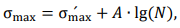 (3)
(3)
where σmax′ — maximum stress in the concentrator in the first half cycle; 𝐴 —coefficient depending on the level of initial deformation and the asymmetry coefficient of the loading cycle at the top of the concentrator.
We accept the obvious assumption that the appearance of brittle fracture may be due to the following reasons:
The latter circumstance turns out to be the stronger the higher the loading speed and the sharper the stress concentrator.
Consider the elastic-plastic plane stress at the top of the concentrator and the elastic state in the gross section: σ𝑚𝑎𝑥 = αTσH ≫ σ0,2, σ𝐻 ≈ σ0,2 and σ𝐻 < σ0,2. Here, σ0,2 — conditional yield strength of the material under uniaxial tension. At αт = 7.3, stiffness of the stressed state is close to the state for a crack. Safety coefficient 𝑚𝐹𝐴𝐷 for a cracklike defect with a plane deformation differs slightly (within 10 %) from 𝑚̅̅̅𝐹𝐴𝐷 ̅̅̅̅ for a crack, i.e., for a state where there is an approximate equality 𝑚𝐹𝐴𝐷 ≈ 𝑚̅̅̅𝐹𝐴𝐷 ̅̅̅̅:
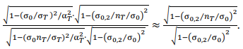 (4)
(4)
Here, 𝑛𝑇 — yield strength margin coefficient, σ0 — local strength of the material at the top of the crack or sharp concentrator.
In [11], the term “local yield strength” is applied to acute stress concentrators when the area of the concentrator adjacent to the top, experiences a complex stress state (CSS). Obviously, this term denotes the material flow stress on the concentrator circuit. There is plane stress state on the surface at its top, and a triaxial CSS appears under the surface. There, stiffness of the stress state increases sharply, therefore, the initial destruction of continuity is formed at some distance from the surface (fig. 4). It is established that the onset of local fluidity in the stress concentrator zone does not coincide with the level determined by the calculations based on strength criteria, particularly, according to von Mises– Huber–Hencky. As the stress concentration increases, the difference increases between:
The results of experiments on plane samples of various steels and alloys [11][16] show that ratio σ∗0,2 ⁄σ0,2 is well approximated by linear dependence on α𝑇. Then, the yield condition can be written as: σ𝑖 = σ0,2 (0.9 + 0.1αт), (5) where σ𝑖 — von Mises stress intensity.
The authors limited their experimental studies to values α𝑇 = 10, and the tests were carried out only on plane samples with centrally located concentrators. In case of plane deformation, stiffness of the stressed state turns out to be slightly higher. Therefore, it is logical to assume that fluidity at some values α𝑇 would occur no earlier than at the plane stressed state. And it is likely that the slope of the straight line according to equation (5) could be somewhat different [11]. However, we focus on this dependence.
For the moment of the beginning of yield, assume that with the transition from elastic deformations to elastoplastic, the ratio of the second and third main stresses to the first σ1 = σmax does not change. This has been proven experimentally.
We equate to (5), the intensity of the stresses of the beginning of von Mises yield according to the fourth (energy) theory of strength, and introduce the coefficients of the relationship between the main stresses under plane deformation: σ1 = σ𝑖 𝐷; σ2 = 𝑞σ1; σ3 = μ𝑇 ⁄ (1 +𝑞)σ1 [15]. Here, μ𝑇 = 0.5 — Poisson's ratio in the plastic region, and 𝐷 — overvoltage coefficient, which takes into account the increase in the first main voltage in the case of CSS. The equation obtained with respect to 𝑞 has two solutions. The first is for tensile σ2 component, the second — for the compressive one. Tensile component σ2 increases stiffness of the stress state in the case of CSS. After transformations and compressions, we can express it like this:
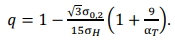 (6)
(6)
For the limiting case σ𝐻 = σ0,2, it is possible to neglect the change in the radius at the top of the concentrator and the onset of some initial global fluidity for the net cross section. Then, the only value α𝑇, satisfying the stiffness of the stress state equivalent to the crack is 7.33. This validates approximate equality (4) obtained earlier. For other values, as can be seen from (6), proportionality 𝑞 will vary depending on value α𝑇 and σ𝐻.
For a crack, coefficient 𝐷 is determined from the equilibrium condition in the elastoplastic region and is calculated for plane deformation from the formula:
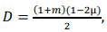 (7)
(7)
where 𝑚 — power hardening coefficient; μ — Poisson's ratio in the elastic region. For ferritic-pearlitic steels, this coefficient takes values from 0,22 to 0,26.
Multiplier before 𝐷 in formula 𝑞 = 1 −2𝐷/√3 for a crack is 1.156, and 𝑞 for ferrite-pearlite steels is 0.73. Indeed, when substituting α𝑇 = 7.3 (6) for σ𝐻 = σ0,2, we get 𝑞 ≅ 0.73. Next, we find α𝑇, if σ0,2⁄σ𝐻 > 1, at which the same stress state is realized as at α𝑇 = 7.3 and σ0,2⁄σ𝐻 → 1.
In [20], the impact of α𝑇 on the effective stress concentration coefficient 𝐾э is investigated, and for a typical aluminum alloy, it is shown that, in the range α𝑇 from 7 to 13, global extremum of the value 𝐾э is observed. It is quite probable that such a significant maximum value may indicate brittle fracture at the initial stages of cyclic loading or discontinuity at the top of the concentrator. In this case, the resource will depend only on the further ability of the material to prevent the propagation of macrocracks.
Model of critical state at the top of an acute macro-stress concentrator. Almost all defects in the welded connection of pipelines, hull ship structures, etc., create a stress concentration. An analytical model developed on the basis of the concept of “local stress concentration factor” is presented in [9]. In addition, a simple dependence was obtained based on the Neuber formula linking the theoretical generalized concentration factor and the concentration factors of the intensity of elastic stresses and deformations. As a result, for the critical value of plasticity in the concentrator focus, the following dependence was obtained:
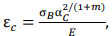 (8)
(8)
where α𝑐 — critical value of the theoretical stress concentration factor; σ𝐵 — modulus of rupture; 𝐸 — modulus of elasticity; 𝑚 — exponent of power hardening.
Dependence (8) gives such high values that are rarely found in practice. For example, with critical logarithmic deformation for steel 50, the critical concentration factor is 26, and for high-strength steel 37KHN3A with σ𝐵 = 1.014 MPa — more than 18. It can be concluded that such plasticity is unattainable until continuity is broken in the first loading cycles. This is not surprising, since it is known that the maximum plasticity value for samples with stress concentrators is significantly lower than for samples without stress concentration. In addition, ε𝑐 should be determined not only by the properties of the material, but also by the conditions for the development of plastic deformation before destruction. Similar results are given by the dependence used in [9]:
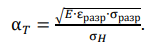 (9)
(9)
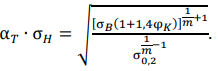
S.A. Kurkin used it for a comparative assessment of the material sensitivity to stress concentration. Here, α𝑇 characterizes the concentrator in which the crack occurs at specific load σ𝐻. Next, we will use the concept of “the most probable initiation of a macrocrack in the concentrator” (born crack) α𝑇 𝑏𝑐 for this case. The true deformation and stress at the moment of occurrence of the discontinuity at the top of the concentrator are denoted respectively by εразр and σразр. They can be determined from the generally accepted formulas εразр ≅ εкр = ln[ 1/(1− φк)] and σразр ≅ 𝑆отр = σв(1 + 1.4φк). Here, 𝑆отр — true stresses of destruction at uniaxial stress state. Note that the fluidity in the concentrator occurs according to (5). Replace σ𝐻 = σ0,2 and σ0,2 with σ∗0,2. As a result, we obtain for the critical states (α𝑇 = σ𝑇𝑏𝑐) relative stresses of the nucleation of destruction σн𝑏𝑐/σ0,2 from the concentrator:
 (10)
(10)
Note that for a very small radius of the concentrator top (ρ < 10𝑑𝑧, where 𝑑𝑧 — average grain diameter), crack propagation is limited at constant α𝑇. As shown in [6], it depends on 𝑑𝑧 of steel. Formulas (8) and (9) are attractive to an engineer because they provide comparing the material sensitivity to stress concentration and using the initial data of the mechanical characteristics of steel.
We can get a slightly different model that takes into account the CSS in the area of the top of the macroconcentrator. The author [12] uses the strength criterion of brittle fracture in the structural material σ1 > 𝑆отр, where 𝑆отр — stress of normal fracture in the approximation to a uniaxial stress state. Significantly, this characteristic of the material does not depend on the temperature of its test. We use this criterion in a slightly different way — for the moment of occurrence of a discontinuity in the area of the top of the stress concentrator. Suppose that 𝑆отр is achievable in the case of constant energy equality at CSS and uniaxial stress state, i.e., with loss of plastic stability and transition from a volumetric stress state (when σ𝑖 is small) to a uniaxial stress state with an inevitable increase in deformations.
We use power approximation of the deformation diagram within the framework of the deformation theory of plasticity. We equate true stresses σ𝑖 of the deformation diagram in the elastic solution function of the problem m σ𝑖 = 𝐹(σ𝑖(𝑦)) to 𝑆отр. As a result, we get:
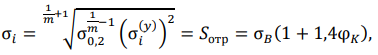 (11)
(11)
where σ𝑖(𝑦) — uniaxial stresses in the elastic solution to the problem. Writing (11) with respect to σ𝑖(𝑦), we obtain an expression for the elastic solution to the stress concentration problem on the other hand: σ𝑖(𝑦) = α𝑇 ∙ σ𝐻. Thus:
 (12)
(12)
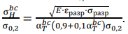
Here, σ𝐻 — nominal workload on the welded joint. In hard points of welded structures, joints or under overloads, it can reach the value of the yield strength of the material. Let us imagine a special case under conditions of cyclic loading with hardening of the material for the moment of formation of the born crack discontinuity — failure initiation. After transformations (12), we write down a simplified formula:
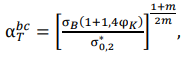 (13)
(13)
where σ𝑇𝑏𝑐 — value of the theoretical stress concentration factor at which the nucleation of destruction occurs in the region of the top of the macro-concentrator; σ∗0,2 — yield strength of the material at the top of the concentrator, which can be increased according to (5) in the case of CSS.
At the moment of equality α𝑇 = σ𝑇𝑏𝑐, the nominal stresses must be equivalent to the nucleation (destruction) stresses σH𝑏𝑐. For this situation (13), we can write in relative values σH𝑏𝑐⁄σ0,2 and construct the dependences of the relative values of the stresses of fracture formation on the theoretical concentration factor σ𝑇𝑏𝑐 = α𝑇:
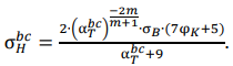 (14)
(14)
Unfortunately, it is not possible to write (14) with respect to σ𝑇𝑏𝑐 at σH𝑏𝑐⁄σ0,2 = 1. However, σ𝑇𝑏𝑐 can be found numerically for specific load σH𝑏𝑐, or diagrams of the danger of discontinuities in the form of a macrocrack in the focus of the concentrator can be constructed.
Dependences are analytically obtained for calculating critical theoretical stress concentration factors related to the mechanical characteristics of the material and a given external static load under the condition of a volumetric stress state for concentrators in welded joints. It is shown that the volume of the stress state in the concentrator focus affects significantly the value of the critical theoretical stress concentration factor. It is established that the complex stress state in the concentrator focus can be controlled by the geometric characteristics of the concentrator itself and its location relative to the external stress field. Experimental data of steels (see Table 1) are obtained from literary sources. These are ferrite-perlite materials for which formula (14) has shown good agreement. Dependence (14) is attractive because standard mechanical characteristics are used as initial data. It can also be used to assess the risk of defects in the fusion zone (fig. 1,fig. 2), where hardening structures are formed, whose properties differ significantly from the initial characteristics of the welded steel.
Solutions for (9) and (14) are used more often for the most brittle steels at low σ𝑇𝑏𝑐. However, in the area of high stress concentration, critical ratios σH𝑏𝑐⁄σ0,2 for different steels will be very close in values. This can be explained by the fact that with the CSS, a stress state similar to a dangerous case is created for all steels in the top region. In the region of small stress concentrations, solutions to model (9) show higher critical stress values σH𝑏𝑐. Note that the average value σ𝑇𝑏𝑐 at σH𝑏𝑐 ≈ σ0,2 is ~8.5. For steels with different mechanical characteristics, it does not change as much as according to the calculated results of model (9).
Figure 5 is constructed to validate the calculation results based on the physical adequacy of model (14). These are graphs of critical state dependences σH𝑏𝑐⁄σ0,2 from σ𝑇𝑏𝑐.
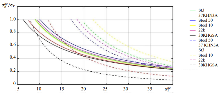
Fig. 5. Dependences of changes in the relative voltage of the external load σH𝑏𝑐⁄σ0,2 from σ𝑇𝑏𝑐 for the critical state at the top of the stress concentrator. Solid curves — formula (14); dotted curves — formula (10)
Model (9), which does not take into account the volume and increase in yield stresses at the top of the concentrator, gives σ𝑇𝑏𝑐 = 91 at stresses σH𝑏𝑐 = 0.5σ0,2 for steel 10, which is unlikely. If we take into account the volume in this model, then σ𝑇𝑏𝑐 = 33, which is significantly less. Taking into account the volume of the stressed state, the critical plastic deformation is reduced to the occurrence of destruction during static tensile of the samples. This was validated by experiments with various steels and alloys6. Moreover, the researchers obtained less ductility of the steels on corroded samples. Here, it was shown that a volumetric stress state was created at the tops, and the volume prevented the free flow of plasticity. The plasticity before the destruction of these samples was 40 %, and the yield strength increased to 27 % [21]. It can be concluded that deeper concentrators cause a greater increase in the yield strength. The results of indirect experiments allowed us to assert that under hydrostatic load, the fluidity is not fixed, in this case the material only embrittles. However, in the focus of the concentrator, with an increase in the external load, the volumetric stress state cannot remain stable enough for the development of a higher volume level. Therefore, bifurcation is inevitable. Further, the development can go in two directions:
Probably, the moment of bifurcation should be considered a critical state in the focus of the concentrator. Perhaps, this moment depends significantly on the depth of the concentrator, its relative length and depth to the thickness of the part, orientation to the external stress field, as well as on the mechanical characteristics and extent of the concentrator focus. All this requires additional research and more precise solutions.
Discussion and Conclusions. Defects and design features of welded joints (weld groove geometry, incomplete penetration, undercuts, pores, hardening structures, etc.) reduce static and fatigue strength. Stress concentrators are typical for welded joints, having a long and shallow shape relative to the thickness of the parts being connected (undercuts) or long and deep (incomplete penetration, etc.). All of them reduce fatigue strength. The analytical models obtained in the presented work allowed us to draw a number of conclusions.
1. The operation of the material at high values of the theoretical stress concentration factor depends on the stress state and its rigidity, as well as on mechanical and structural characteristics. The latter may differ from the parameters of the source material, since the tops of the concentrators may be located in the fusion zones of welded joints.
2. A rigid stress state in the stress concentrator focus can cause an increase in the yield strength. In this case, the passage of shear deformation is restrained, and the onset of the limiting state is achieved at a lower value of the theoretical stress concentration factor and is characterized by discontinuity at a constant value of the external load.
3. Comparison of high-strength steels with ductile and ordinary strength steels at the same level σH𝑏𝑐⁄σ0,2. In the second case, the formation of the volume of the stress state will have a more significant effect on the change in the critical value of the theoretical stress concentration factor, at which the nucleation of destruction occurs in the region of the top of the macro-concentrator α𝑇 𝑏𝑐 (fig. 5).
4. Comparison of models (14) and (10) allows us to draw a certain conclusion. Taking into account the rigidity of the stress state and the increase in the yield strength at σH𝑏𝑐⁄σ0,2 → 1 from below, (10) gives estimate σ𝑇𝑏𝑐 with a margin of safety, if we are talking about σH𝑏𝑐⁄σ0,2 = 0.8 (30KHGSA). For less durable steel (14), the margin of strength at σH𝑏𝑐⁄σ0,2 = 0.5 (37KHN3A), etc. Thus, it is preferable to take into account the volume and use model (14).
5. The dependences on the diagram of the theoretical stress factors are more densely grouped in (14), than in (10) due to very similar stress states in the region of the tops of acute stress concentrators. Therefore, the mechanical characteristics of steels have a secondary effect on σ𝑇𝑏𝑐.
6. With an increase in the theoretical stress concentration factor and a decrease in σ𝑇𝑏𝑐 at the same level σH𝑏𝑐⁄σ0,2 of the external load, the influence of the structural factor in steel on the occurrence of initial destruction (formation of discontinuity) reduces. However, for further destruction, the resistance of the material to macrocrack growth is essential. After its occurrence, other criteria of mechanics and kinetics of destruction are triggered. The presented study can serve as a prerequisite for the development of analytical models to assess the residual life of welded joints and structures exposed to cyclic loads. Further research will presumably refine the analytical models. The authors will check and test the results through CAE modeling and proceed to the evaluation of effective stress concentration factors.
1. Sergeev NN, Sergeev AN. Mekhanicheskie svoistva i vnutrennee trenie vysokoprochnykh stalei v korrozionnykh sredakh. Vologda: InfraInzheneriya; 2020. 431 p. (In Russ.)
2. Molokov KA, Novikov VV, Turmov GP. Osnovy raschetnogo proektirovaniya svarnykh konstruktsii. Vladivostok, 2019. T. 1. 204 p. (In Russ.)
3. Molokov KA. Otsenka povrezhdennosti ferrito-perlitnykh stalei v usloviyakh malotsiklovogo nagruzheniya. In: Proc. Conf. “Nauka. Innovatsii. Tekhnika i tekhnologii: problemy, dostizheniya i perspektivy”. URL: https://elibrary.ru/item.asp?id=23752241&selid=46181945 (accessed: 31.10.2022). (In Russ.)
4. Molokov KA. Otsenka povrezhdennosti ferrito-perlitnykh stalei v usloviyakh malotsiklovogo nagruzheniya.
5. Sergeev NN, Sergeev AN. Mekhanicheskie svoistva i vnutrennee trenie vysokoprochnykh stalei v korrozionnykh sredakh. Vologda: InfraInzheneriya; 2020. 432 p. (In Russ.)
6. Krokha VA. Uprochnenie metallov pri kholodnoi plasticheskoi deformatsii. Moscow: Mashinostroenie: 1980. 157 p. (In Russ.)
1. Molokov KA, Novikov VV, Turmov GP, et al. Estimation of Reliability of Ship Structures with Microcracks and Residual Welding Stresses. Marine Intellectual Technologies. 2018;41:45–54.
2. Novikov VV, Turmov GP, Surov OE, et al. Povrezhdeniya i raschetnyi analiz prochnosti korabel'nykh konstruktsii. Vladivostok: Far Eastern Federal University; 2020. 266 p. (In Russ.)
3. Erofeev VV, Ignatiev AG, Oleinik NI, et al. Mathematical Model for Assessing Stress Concentration Factors in T-Shaped Welded Joints. Information Technology. 2021;17:28–36.
4. Molokov K, Sakharova A, Mikhalev M. Crack Propagation-Based Assessment of the Endurance Limits of Welded Joints. FEFU: School of Engineering Bulletin. 2017;30:42–51. https://doi.org/10.5281/zenodo.399005
5. Kazanov GT, Novikov VV, Turmov GP. Kontsentratsiya napryazhenii i drugie osobennosti napryazhennogo sostoyaniya sudovykh korpusnykh konstruktsii. Vladivostok: Far Eastern Federal University; 2014. 178 p. (In Russ.)
6. Molokov KA, Novikov VV, Turmov GP, et al. Matematicheskie modeli otsenki ehkspluatatsionnogo resursa i rabotosposobnosti sudovykh svarnykh konstruktsii. Vladivostok: Far Eastern Federal University; 2021. 240 p. (In Russ.)
7. Emelianov OV, Shapovalov EL, Gavrilov VB. The Level of Concentration of Elastic Stresses in Butt Welded Connections Depending on Design Parameters. BST: Byulleten' stroitel'noi tekhniki. 2017;999:26–28.
8. Makhutov NA, Albagachiev AYu, Alekseeva SI, et al. Prochnost', resurs, zhivuchest' i bezopasnost' mashin. Moscow: Librokom; 2008. 576 p. (In Russ.)
9. Yamaleev KM, Gumerova LR. Strukturnye aspekty razrusheniya metalla nefteprovodov. Ufa: Gilem; 2011. 144 p. (In Russ.)
10. Khazhinskiy GM. Deformirovanie. Razrushenie. Nadezhnost': Zadachi deformirovaniya i razrusheniya stali. Metody otsenki prochnosti ehnergeticheskogo oborudovaniya i truboprovodov. Moscow: Lenand; 2014. 544 p. (In Russ.)
11. Larionov VP, Filippov VV. Khladostoikost' materialov i ehlementov konstruktsii: rezul'taty i perspektivy. Novosibirsk: Nauka; 2005. 290 p. (In Russ.)
12. Kryzhevich GB. Limit and Fatigue Strength Calculation Methods for Arctic Marine Structures. Transactions of the Krylov State Research Centre. 2019;388:41–54. http://doi.org/10.24937/2542-2324-2019-2-388-41-54.
13. Smirnov AN, Muravyev VV, Ababkov NV. Razrushenie i diagnostika metallov. Moscow: Innovatsionnoe mashinostroenie; 2016. 479 p. (In Russ.)
14. Negoda EN. Fatigue of Welded Joints of Large Diameter Pipes. FEFU: School of Engineering Bulletin. 2015;25:62–74.
15. Matokhin GV, Gorbachev KP. Inzheneru o soprotivlenii materialov razrusheniyu. Vladivostok: Dal'nauka; 2010. 281 p. (In Russ.)
16. Mitenkov FM, Volkov IA, Igumnov LA, et al. Prikladnaya teoriya plastichnosti. Moscow: Fizmatlit; 2015. 284 p. (In Russ.)
17. Levin VA, Vershinin AV. Nelineinaya vychislitel'naya mekhanika prochnosti. Vol. 2. Chislennye metody. Moscow: Fizmatlit; 2015. 544 p. (In Russ.)
18. Matvienko YuG. Dvukhparametricheskaya mekhanika razrusheniya. Moscow: Fizmatlit; 2021. 208 p. (In Russ.)
19. Panferov VM. Kontsentratsiya napryazhenii pri uprugoplasticheskikh deformatsiyakh. Izvestiya akademii nauk SSSR. Otdelenie tekhnicheskikh nauk. Mekhanika i mashinostroenie. 1954;4:47–65. (In Russ.)
20. Huy Duong Bui. Fracture Mechanics: Inverse Problems and Solutions. Moscow: Fizmatlit; 2011. 412 p. (In Russ.)
21. Petrova NE, Baeva LS. Biokorroziya korpusov sudov. Vestnik of MSTU. Proceedings of MSTU. 2006;9:890–892. (In Russ.)
Konstantin А Molokov, associate professor of the Department of Industrial Safety, Polytechnic Institute, associate professor of the Information Technologies and Systems
8, Sukhanova St., Vladivostok, 690091
41, Gogoleva St., Vladivostok, 690014
Valery V Novikov, associate professor of the Department of Marine Engineering and Transport, Polytechnic Institute, Cand.Sci. (Eng.)
8, Sukhanova St., Vladivostok, 690091
Mohammad Dabalez, graduate student of the Department of Industrial Safety, Polytechnic Institute
8, Sukhanova St., Vladivostok, 690091
Molokov K.А., Novikov V.V., Dabalez M. Evaluation of the Occurrence of Initial Failures from Stress Concentrators in Welded Joints and Structural Elements. Advanced Engineering Research (Rostov-on-Don). 2023;23(1):41-54. https://doi.org/10.23947/2687-1653-2023-23-1-41-54


Advanced Engineering Research (Rostov-on-Don)
ISSN 2687-1653 (Online)
Contact with: Publisher / Editorial Office of the Journal
Publisher: Don State Technical University - DSTU, Rostov-on-Don, Russia - https://donstu.ru/en/
Editor-in-Chief: Alexey N. Beskopylny, Dr.Sci. (Eng.), Professor, Vice-Rector, Don State Technical University (Rostov-on-Don, Russia)
Don State Technical University
1, Gagarin Sq., Rostov-on-Don, 344003, Russia
tel.: +7 (863) 2738-372, e-mail: vestnik@donstu.ru
16+
Processing of personal data


