


Contents
Scroll to:
https://doi.org/10.23947/2687-1653-2023-23-3-283-295
Scroll to:
Introduction. Long-stroke movements in automated pneumatic drives account for a significant number of executive movements in coordinate tables, automated warehouses, cutting machines, etc. Long-stroke movements degrade the dynamic quality and positioning of the drive. This is due to the friction of the piston and the nonlinear characteristics of the compressed gas flow in significant volumes of the pressure and drain cavities of the cylinder. Thus, it seems promising to create an automated position pneumatic actuator for long-stroke movements. This will increase the productivity of processes while providing the declared accuracy. The objective of the work is to obtain a mathematical model and dependences of the critical parameters of the proposed automated position long-stroke pneumatic drive of fabrication system in the areas of acceleration, steady-speed movement, deceleration, and braking.
Materials and Methods. The basis for calculations and modeling was the scheme of two trajectories of movement from point A to point E, taking into account the forces expended on these processes. The optimal displacement was determined using the Portnyagin’s principle (i.e., optimal performance). Proportional drive control was presented as a method of achieving the result. For long-stroke drive movements, schematic solution and design scheme were visualized in detail (presented as drawings). An original jet sensor with an internal pneumatic connection and a pneumo-mechanic discrete-proportional device for the control loop performance were proposed. The mathematical model included the movement and braking of the piston, the balance of mass flow, the pressure at points, and the control loop. The system of equations was solved by the Runge — Kutta method in the SimInTech software product. Based on the results of the study of a generalized mathematical model, the dependences of changes in the kinematic, power and pneumatic properties of the drive were constructed in real time during a typical positioning cycle. The information was summarized and presented as a set of graphs.
Results. The mathematical model was formed according to a set of calculations. It took into account the dependences characteristic of the movement of the piston of the pneumatic cylinder. The balance of mass flow was investigated by the equations of gas flow during compression in the chamber, through distributors and throttles, in the discharge and drain cavities and in the control device. Inequalities describing the pressures at the points and the control loop were considered. A complex mathematical model was solved in the SimInTech software environment by the Runge — Kutta method with a variable integration step. A fragment of the program was selected as one of the illustrations. It showed that the software used the following indicators for calculations: target and reduced coordinates; absolute gas constant; coefficients of spring stiffness, resistance, adiabatic and viscous friction in the piston; compressor pressure; mass of the moving parts of the pneumatic actuator; strength of external resistances; diameters of the pipeline, the pneumatic cylinder piston and the braking device; length of the stroke of the cylinder piston; area of piston cavities and throttles; length of the pipeline and its internal volume. Thus, the program manipulated a significant set of data, which made it possible to obtain meaningful and adequate results. The relationship of blocks and diagrams used in solving the model was schematically shown. We are talking about graphs of movements, areas, pressures, velocities and temperatures. Blocks with the program text and intended for integration were used. Thus, a mathematical model of an automated pneumatic drive of the fabrication system and the dependences of the basic parameters of its operation were obtained. The graphs indicated that the operating mechanism of the pneumatic actuator properly followed the proposed trajectory.
Discussion and Conclusion. The research results allowed us to consider several stages of long-stroke movement of the drive, to determine the time frame of these processes (from 0 to 0.65s), as well as changes in pressure and speed of movement of the pneumatic cylinder carriage recorded in these intervals. There were five such stages: acceleration, steady-speed movement, deceleration, movement with positioning speed, and braking. Further research will focus on optimizing the system to reduce the duration and maintain accurate positioning under external influences.
Korotych D.A., Sidorenko V.S., Prikhodko S.P. Investigation of Dynamic Characteristics of an Automated Position Long-Stroke Pneumatic Actuator of Fabrication System. Advanced Engineering Research (Rostov-on-Don). 2023;23(3):283-295. https://doi.org/10.23947/2687-1653-2023-23-3-283-295
Introduction. The performance of the drives is determined by the accuracy of positioning and the speed of movement of the coordinates in different operating cycles. Modern fabrication systems are often equipped with automatic pneumatic actuators, which are characterized by long-stroke movements. These are, e.g., gantry resistance welding machines, coordinate tables, and cutting devices.
Modern positioning pneumatic actuators for long-stroke movements in fabrication equipment provide a speed of up to 30 mm/s and an accuracy of ~1 % of the travel length. Customized actuators provide positioning accuracy of 0.4 % at speeds up to 100 mm /s. Note that the trajectory of movements is formed by the compressed air flow control in pressure or drain pipelines and the pneumatic cylinder sides. In long-stroke drives, the length of such sides reaches 3 m. Complex thermodynamic processes and compressibility in air flows are the key factors limiting the increase in accuracy [1–3].
Thus, it is necessary to increase the productivity of the working and engineering processes of the equipment while providing the declared accuracy. In this case, it seems promising to create an automated positioning pneumatic actuator for long-stroke movements. The new solution should take into account such characteristics of the pneumatic actuator as speed, weight-size parameters, explosionproof, and fire protectability [2][4].
The objective of the work is to obtain a mathematical model and dependences of the key parameters of the proposed automated positioning long-stroke pneumatic drive of industrial equipment in the areas of acceleration, steady-speed movement, deceleration, and braking.
Materials and Methods. Figure 1 shows schematically the transport problem of moving from point А to point Е along two trajectories. The forces expended on each of the movements are taken into account. The suboptimal movement ABCDE (trapezoid) with a simple control algorithm is realized in time 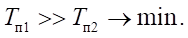
The optimal displacement AFE (bell) was obtained by solving the optimal speed based on the Portnyagin’s principle 
 The result was achieved with more complex proportional control of the drive. The trajectory of movement provided the accuracy of switching motion controls along path
Fig. 1. Movement trajectories: 1 — suboptimal ABCDE; 2 — optimal AFE
In the description of trajectory 1, the switching points are indicated in Latin letters: А — for acceleration of the drive; В — for deceleration; С — for positioning speed; D — for stopping. In sections AB and BC, initial acceleration and braking are provided up to the positioning speed  and further stopping by the braking device
When moving along the second trajectory, А — switching to acceleration of the drive; F — switching to stop.
An original jet sensor with an internal pneumatic connection and a pneumo-mechanical discrete-proportional device are proposed, which provides increasing the control circuit speed, since feedback in known analogues reduces the accuracy of the main engine by about 10–15 % during long strokes [4–6].
A schematic solution of a pneumatic positioning drive for long-stroke movements is shown in Figure 2. The drive operates in accordance with the suboptimal motion trajectory determined in the optimal speed problem for a given positioning accuracy. Here, ПЦ1 — rodless pneumatic cylinder of long-stroke movements, which carries out the main motion; ПЦ2, ПЦ3 — brake pneumatic cylinders that fix the drive; СА — jet sensor that determines the coordinate of movement, acceleration of the drive, its speed and force; Р1 — pneumatic distributor with electropneumatic control, it controls the supply to the jet sensor; Р2 — main control distributor; Р3 — distributor with pneumatic control, it controls the operation of pneumatic brake cylinders; Г1–Г4 — mufflers responsible for pressure relief into the atmosphere; ДД — pressure sensor receiving data from the jet sensor; ПЛК — logic controller; ШД — stepper motor controlling the distributor spool; БПВ — air-preparation unit; ДР1, ДР2 — throttle with check valve, used to regulate the speed of the rodless pneumatic cylinder of long-stroke movements of the main motion [7].
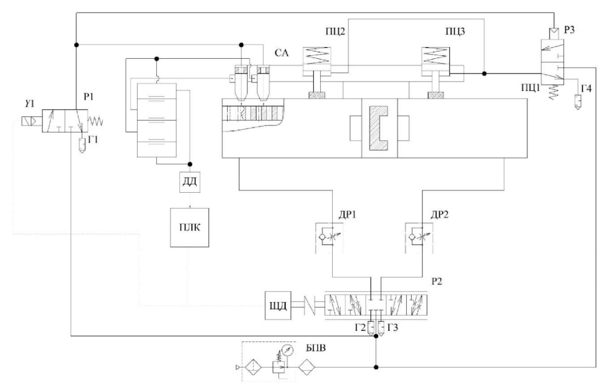
Fig. 2. Circuit design proposal of an automated positioning long-stroke pneumatic actuator
The drive contains a control system that monitors the position of the carriage of a rodless pneumatic cylinder, slows down when approaching the specified coordinates, and sends a signal to the braking gear [1][4][7].
The speed is increased by the introduction of a discrete proportional control device. Signals generated by the control loop are used for control. The device is made in the form of two nozzles and contains compensation measurements.
Research Results. The design scheme of the pneumatic drive of long-stroke movements is shown in Figure 3.
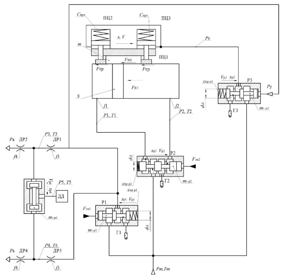
Fig. 3. Diagram of the automated pneumatic drive of long-stroke movements of the industrial equipment
Here, ПЦ1 — rodless pneumatic cylinder of long-stroke coordinate movements, carrying out the main motion; ПЦ2, ПЦ3 — brake pneumatic cylinders that fix the drive during a stop in the desired position; СА — jet sensor that determines the coordinate of movement, acceleration of the drive, its speed and force; Р1 — pneumatic distributor with electropneumatic control, it controls the supply to the jet sensor; Р2 — main control distributor; Р3 — distributor with pneumatic control, it controls the operation of brake pneumatic cylinders; Г1–Г4 — mufflers responsible for pressure relief into the atmosphere; ДР1–ДР2 — throttle with a check valve, which serves to regulate the speed of a rodless pneumatic cylinder of long-stroke movements of the main motion; ДД — pressure sensor receiving data from a jet sensor; S — piston area of a rodless pneumatic cylinder of long–stroke coordinate displacements; P1–Р5 — investigated pressures at points 1–5; Т1–Т5 — investigated temperatures at points 1–5; Fтр — friction force in a rodless pneumatic cylinder of long-stroke displacements; Fвт — viscous friction force in a rodless pneumatic cylinder of long-stroke displacements; Fвн — external force in the rodless pneumatic cylinder of long-stroke movements; x — travel of the carriage of the rodless pneumatic cylinder of long-stroke movements; V — travel speed of the rodless pneumatic cylinder carriage; Cпр — spring rate of brake pneumatic cylinders; m — mass to be moved; Рт — pressure in brake cylinders; Ру — pressure in the control channel; f1–f4 — areas of the through sections; Ра — atmospheric pressure; dз1–dз3 — diameters of distributor spools; Спрр1–Спрр3 — spring rate of distributors 1–3; xp1–xp4 — displacement of distributor spools 1–4; Vp1–Vp4 — travel speed of distributor spools 1–4; Fэм1–Fэм2 — force of the distributor control electromagnet 1–2; Pm — compressor pressure; Tm — temperature generated by the compressor.
The mathematical model was formed with the following assumptions [8–12]:
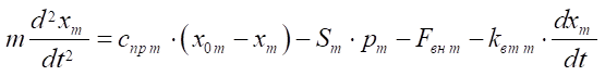
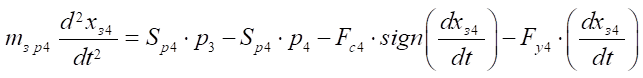
1. Equation of motion of the pneumatic cylinder piston [1][4]:
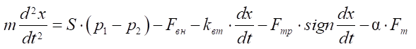 . (1)
. (1)
Here, S — area of the piston of the discharge and drain sides of the rodless pneumatic cylinder of long-stroke coordinate movements of the main motion, m2;
 — air pressure in the discharge and drain sides of the pneumatic cylinder, Pa;
 — external forces, N;
kвт — viscosity friction coefficient;
 — friction force, N;
α — Boolean parameter: α = 0 at  and α = 1 at
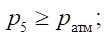
 — pressure in the control channel, Pa;
 — atmospheric pressure, Pa [12–14];
 — mass of the moving parts of the drive, kg;
FТ — braking force, N.
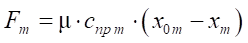 , (2)
, (2)
where cпр т — spring rate of the pneumatic cylinder of the brake; μ — friction ratio.
2. Equation of motion of the piston of the braking pneumatic cylinder:
 . (3)
. (3)
Here, cпр т — spring rate of the brake pneumatic cylinder; х0т — coordinate of the initial compression; ST — effective area of the piston of the drain side of the brake pneumatic cylinder, m2; PM— air pressure, respectively, in the discharge side of the brake pneumatic cylinder, Pa; FВН Т — external forces, N; kвт т — viscosity friction coefficient.
3. Mass expenditure balance equations:
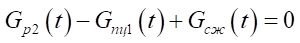 , (4)
, (4)
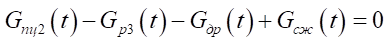 , (5)
, (5)
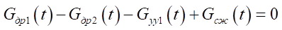 , (6)
, (6)
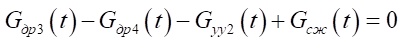 , (7)
, (7)
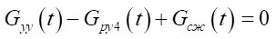 . (8)
. (8)
Here,
 — gas mass flow rate under compression in the chamber;
 — mass flow through distributors;
 mass flow rate in the discharge and drain chambers of a rodless pneumatic cylinder of long-stroke movements;
 — mass flow through throttles in the drain line, at the inlet to the nozzle unit of the jet sensor and at the outlet of the nozzle unit;
 — mass flow rate in the control channels of the control device, at the outlet of the control device, distributor of brake pneumatic cylinders [7].
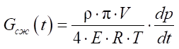 , (9)
, (9)
where
 — air density;
 — volume of the chamber;
R = 287 J/(kgk) — gas constant;
 — volume modulus of elasticity of air;
 — temperature at the point;
 — pressure variation at the point [6].
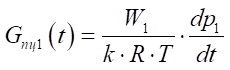 , (10)
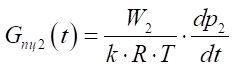 , (11)
where W1 and W2 — current volumes in the pressure and drain sides of the base pneumatic cylinder, m3; k — adiabatic exponent (for air, k = 1.4).
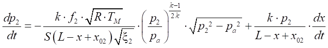
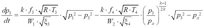
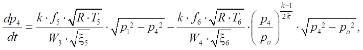
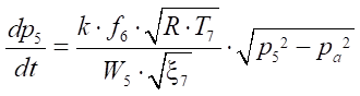
4. Pressure equations in points:
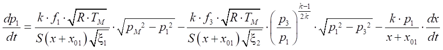 , (12)
 , (13)
 , (14)
 (15)
(15)
 . (16)
Here, k — adiabatic exponent; R — gas constant, J/ ; TМ — air temperature in the main line, К; Pa — atmospheric pressure, Pa; P1 - P5 — pressure in the flow parts of the pipeline, Pa; W1 - W5 — volumes of the flow parts, m3; x1 - x7 — resistance values in the line; f1 - f6 — areas of the flow sections of the pipeline, m2; L — maximum stroke of the piston, m; x01, x02 — ratio of the initial volumes of the pneumatic actuator to the useful area of the piston side of the pneumatic cylinder, m;
 — piston speed, m/s.
5. Control loop equations.
Equation of motion of the distributor spool 1:
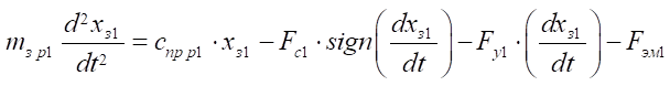 . (17)
Equation of motion of the distributor spool 2:
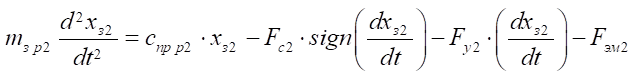 . (18)
Equation of motion of the distributor spool 3:
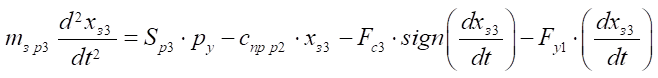 . (19)
Equation of motion of the distributor spool 4:
 . (20)
Here, Sp — area of the distributor spool end face, m2; P3, P4, Py — pressure in the control channels, Pа; Fc — resistance forces to the movement of the distributor spool, N; Fy — reaction forces of stops, N; FЭМ — force of the electromagnet acting on the distributor spool, N; cпр р — spring compression ratio, N/m; mзр — weight of the distributor spool, kg.
To solve the mathematical model, SimInTech software product was used. We applied the Runge–Kutta method with a variable integration step (Fig. 4–5).
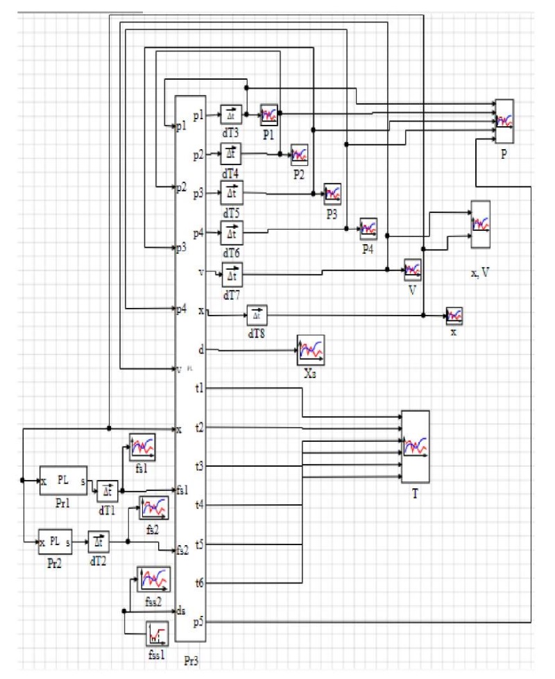
Fig. 4. Model fragment in SimInTech program
Here, Pr1–Pr3 — blocks with the program text; fs1, fs2 — graphs of the output of areas 1 and 2 of the jet sensor throttle; fss1 — block of the problem of the areas of the flow sections of the jet sensor; fss2 — graphs of the output of the areas of the flow sections of the jet sensor; dT1–dT8 — integration blocks; Р1–Р4 — graphs of the output of the received pressures at points 1–4; Р — general schedule for the output of all pressures; V — graph of the obtained speed output of the rodless pneumatic cylinder carriage; х — graph of the received movement output of the rodless pneumatic cylinder carriage; х, V — general graph of the output of the received movement and the speed of the rodless pneumatic cylinder carriage; Т — graphs of the output of the obtained temperatures; Хз — graph of the received movement output of the control distributor spool.
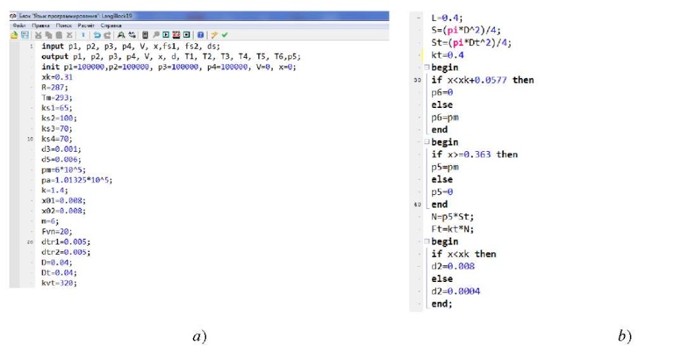
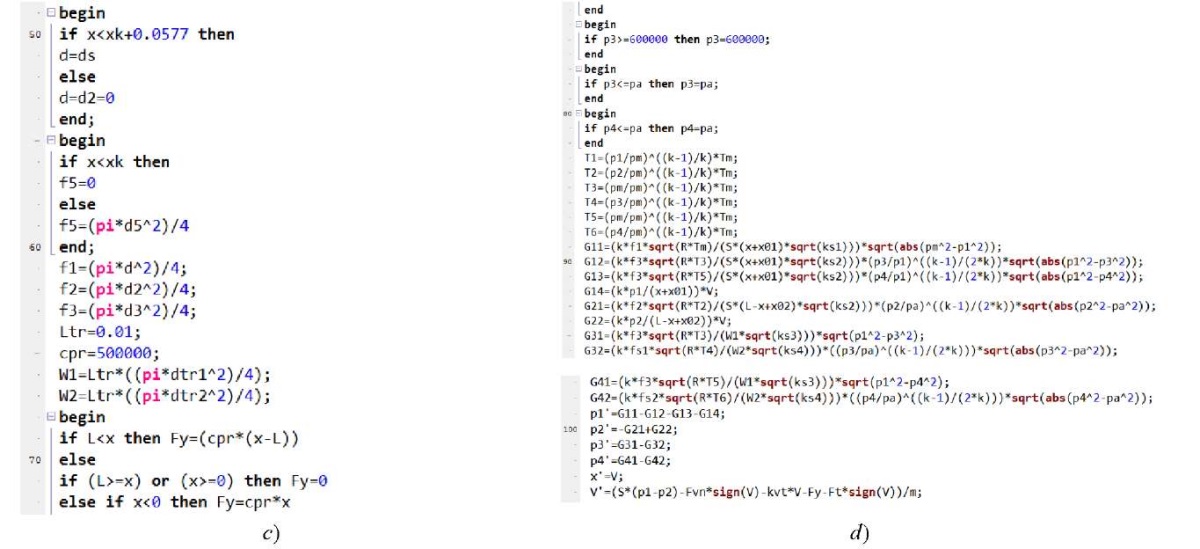
Fig. 5. Programming block in SimInTech:
a — part of the source data;
b — part of the logical functions;
c — part of the assignment of variables;
d — skeletal code
The study of the generalized mathematical model of the proposed drive made it possible to obtain graphs of the behavior of the drive during acceleration, deceleration, and stop (Fig. 6), describing the changes in kinematic, power and pneumatic properties of the drive during a typical positioning cycle in real time [15].
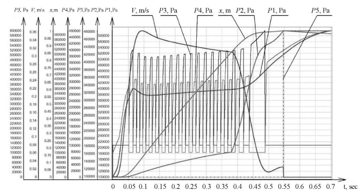
Fig. 6. A set of graphs based on the data of a generalized mathematical model
Discussion and Conclusion. The graph shows a long-stroke movement along the trajectory proposed in Figure 1. The operation of the drive consists of several stages.
The graphs obtained confirm that the long-stroke movements of the pneumatic actuator are performed in accordance with the proposed trajectory (Fig. 1), and the control system functions properly. Further research will focus on optimizing the system to reduce the duration and maintain accurate positioning under external influences.
1. Korotych DA, Sidorenko VS. Pozitsionnaya sistema upravleniya dlinnokhodovymi pnevmoprivodami. In: Proc. XXIII Int. Sci.-Tech. Conf. of students and postgraduates “Hydraulic Machines, Hydraulic Drives and Hydropneumoautomatics”, dedicated to the 100th anniversary of Boris T. Emtsev, Dr.Sci. (Eng.), Honored Professor of MEI, Honorary Academician of Water Sciences. Moscow: Izd-vo “Mir nauki”; 2019. P. 157–163. URL: https://www.elibrary.ru/item.asp?id=41599329 (accessed: 04.05.2023). (In Russ.)
2. Jihong Wang, Gordon T. Energy Optimal Control of Servo-Pneumatic Cylinders through Nonlinear Static Feedback Linearization. Journal of Dynamic Systems, Measurement, and Control. 2012;134(5):051005. https://doi.org/10.1115/1.4006084
3. Dao The Anh. Pozitsionnyi pnevmoprivod povyshennogo bystrodeistviya i tochnosti. Cand.Sci. (Engineering) diss. Rostov-on-Don; 2016. 206 p. URL: https://viewer.rsl.ru/ru/rsl01008559478 (accessed: 04.05.2023). (In Russ.)
4. Sidorenko VS, Korotych DA, Grishenko VI, Kharchenko AN. Simulation of Pneumatic Actuator Position System for Long Stroke Mounting Movements. IOP Conference Series: Materials Science and Engineering. 2021;1029:012039. https://doi.org/10.1088/1757-899X/1029/1/012039
5. Gallyamov ShR, Starikov KV, Celischev VA. Experimental Research of Characteristics of the Pneumatic Actuator FESTO with Proportional Allocation of the Expenditure. Vestnik UGATU. 2011;15(1)(41):26–33. URL: http://journal.ugatu.su/index.php/Vestnik/article/view/900 (accessed: 04.05.2023).
6. Mosadegh B, Polygerinos P, Keplinger Ch, Wennstedt S, Shepherd RF, Gupta U, et al. Pneumatic Networks for Soft Robotics that Actuate Rapidly. Advanced Functional Materials. 2014;24(15):2163–2170. https://doi.org/10.1002/adfm.201303288
7. Dao The Anh, Sidorenko VS. The Study of the Dynamical System High-Speed Pneumatic Robot Position. Fundamental research. 2015;(7–2):285–292. URL: https://fundamental-research.ru/ru/article/view?id=38687 (accessed: 06.05.2023).
8. Dolgov GA. Kombinirovannyi pnevmoprivod povorotno-delitel'nykh mekhanizmov povyshennogo bystrodeistviya i tochnosti. In: Proc. XXIII Int. Sci.-Tech. Conf. of students and postgraduates “Hydraulic Machines, Hydraulic Drives and Hydropneumoautomatics”, dedicated to the 100th anniversary of Boris T. Emtsev, Dr.Sci. (Eng.), Honored Professor of MEI, Honorary Academician of Water Sciences. Moscow: Izd-vo “Mir nauki”; 2019. P. 119–126.
9. Lemeshko M, Molev M, Golovin I. Hydraulic Technological Machines with Adaptive Drive Structure. MATEC Web of Conferences. 2018;224:02087. https://doi.org/10.1051/matecconf/201822402087
10. Dao The Anh, Sidorenko VS, Dymochkin DD. Study on Positioning Accuracy of Automated Pneumatic Drive with an Outer Brake. Vestnik of DSTU. 2015;15(4):46–53. https://doi.org/10.12737/16077
11. Gorin A, Tokmakov N, Kyznetsov I. Substantiation of Parameters of Machine with Volumetric Hydraulic Drive for Formation of Wells in Ground. In: Proc. 5th International Conference on Industrial Engineering (ICIE). Cham: Springer; 2019. P. 1315–1323. URL: https://link.springer.com/chapter/10.1007/978-3-030-22063-1_139 (accessed: 04.05.2023).
12. Vardhan A, Dasgupta K, Mishra SK. Dynamic Analysis of a Closed-Circuit Hydraulic Drive System Used in the Rotary Head of Blasthole Drilling Machine Using MATLAB-Simulink Environment. In: Proceedings of the Institution of Mechanical Engineers, Part I: Journal of Systems and Control Engineering. 2019;233(6):702–719. https://doi.org/10.1177/0959651818808870
13. Obukhova EN, Grishchenko VI, Dolgov GA. Formalization of Dynamic Model of Pneumatic Drive with Variable Structure. MATEC Web of Conferences. 2018;226:02022. https://doi.org/10.1051/matecconf/201822602022
14. Seppe Terryn, Joost Brancart, Dirk Lefeber, Guy Van Assche, Bram Vanderborght. Self-Healing Soft Pneumatic Robots. Science Robotics. 2017;2(9):4268. https://www.science.org/doi/10.1126/scirobotics.aan4268 (accessed: 04.05.2023).
15. Obukhova EN, Popov AN. Synergetic Synthesis of Nonlinear Adaptive Control for Pneumatic Drives. In: Proc. IV Int. Conf. on Control in Technical Systems (CTS). New York: IEEE; 2021. https://doi.org/10.1109/CTS53513.2021.9562786
Daniil A. Korotych, Teaching assistant and Postgraduate student of the Hydraulics, Hydropneumoautomatics and Heat Management Department
1, Gagarin sq., Rostov-on-Don, 344003
Valentin S. Sidorenko, Dr.Sci. (Eng.), Professor of the Hydraulics, Hydropneumoautomatics and Heat Management Department
1, Gagarin sq., Rostov-on-Don, 344003
Sergey P. Prikhodko, Teaching assistant and Postgraduate student of the Hydraulics, Hydropneumoautomatics and Heat Management Department
1, Gagarin sq., Rostov-on-Don, 344003
Korotych D.A., Sidorenko V.S., Prikhodko S.P. Investigation of Dynamic Characteristics of an Automated Position Long-Stroke Pneumatic Actuator of Fabrication System. Advanced Engineering Research (Rostov-on-Don). 2023;23(3):283-295. https://doi.org/10.23947/2687-1653-2023-23-3-283-295


Advanced Engineering Research (Rostov-on-Don)
ISSN 2687-1653 (Online)
Contact with: Publisher / Editorial Office of the Journal
Publisher: Don State Technical University - DSTU, Rostov-on-Don, Russia - https://donstu.ru/en/
Editor-in-Chief: Alexey N. Beskopylny, Dr.Sci. (Eng.), Professor, Vice-Rector, Don State Technical University (Rostov-on-Don, Russia)
Don State Technical University
1, Gagarin Sq., Rostov-on-Don, 344003, Russia
tel.: +7 (863) 2738-372, e-mail: vestnik@donstu.ru
16+
Processing of personal data


