


Contents
Scroll to:
https://doi.org/10.23947/2687-1653-2023-23-4-356-364
EDN: IQHEGM
Scroll to:
Introduction. Mobile robots capable of omnidirectional movement are widely used in various fields of human activity. To provide high accuracy of positioning of omnidirectional platforms with mecanum wheels, it is required to develop their detailed mathematical models used in the construction of a motion control system. Due to the complicated design of the mecanum wheels, various errors may occur during the construction of omnidirectional platforms, including the error of installing such wheels on the platform. Its effect on the accuracy of the platform movement has not been studied before. This work aims at assessing the positioning errors that arise due to the presence of design errors in the installation of mecanum wheels, and analyzing the effect of these errors on the accuracy of program motion testing when using control at the kinematic level.
Materials and Methods. The analysis of positioning accuracy was based on mathematical modeling of the platform kinematics, taking into account structural errors in the installation of mecanum wheels. To describe the relationship between the angular speeds of rotation of the wheels and the speeds of the platform, the conditions of nonslip of the contact points on the support surface were used. Numerical calculations were carried out in the Wolfram Mathematica package.
Results. A formula was obtained for estimating errors in platform pseudovelocities under program control formed at the kinematic level. The estimation of the errors of the platform speeds for simple movements was carried out. According to the calculation results, it has been shown that the speed errors are significant for robots with mecanum wheels operating autonomously.
Discussion and Conclusion. The calculation results demonstrated the significant impact of wheel installation errors on the positioning accuracy of the mecanum-platform, and confirmed the need to take into account these design errors when creating autonomous mecanum-platforms. The constructed model of the robot's kinematics makes it possible to predict errors in platform speeds that arise under program control, as well as deviations of the coordinates of the geometric center of the platform from the program motion. The proposed kinematic model can be used to improve the positioning accuracy through forming a platform motion control that compensates for the influence of wheel installation errors.
Pankrateva G.V., Mordin A.E., Saypulaev G.R. Analysis of Positioning Accuracy in Case of Design Errors in the Installation of Mecanum Wheels of the Mobile Platform. Advanced Engineering Research (Rostov-on-Don). 2023;23(4):356-364. https://doi.org/10.23947/2687-1653-2023-23-4-356-364. EDN: IQHEGM
Introduction. Mobile robots (or omnidirectional platforms) capable of moving in any direction are widely used in the military, medical, educational, and industrial fields of human activity [1][2]. The possibility of omnidirectional movement can be achieved by equipping the mobile platform with omni-wheels of various types (mekanum wheels, classic omni-wheels). To provide high accuracy of positioning omnidirectional platforms, it is required to develop their detailed mathematical models for the construction of a motion control system. The need for maintaining high accuracy of movement is associated with the demand to make omnidirectional platforms operate autonomously.
Often, when mathematically modeling the kinematics of mecanum wheels, assumptions are made that simplify the description of the movement of such wheels. Specifically, this is discussed in [3–5]. Thus, in [3][4], the dynamics of the mecanum platform is considered, taking into account the rolling dry friction forces and the conditions of non-slip contact points, expressed by non-holonomic bonds. In [5], it is emphasized that studying the influence of the finite linear dimensions of the rollers and vibrations associated with this effect on the dynamics of the mecanum platform is of interest.
The urgently needed lines of research on omnidirectional wheels are modeling the effect of the design of the mekanum wheel rollers, and optimizing the shape of rollers [6–9]. The requirement to optimize the shape of rollers is due to the fact that with some forms of omni-wheel rollers, vertical vibrations of contact points may occur when moving omnidirectional platforms (for more information, see the patent review [10]).
Another factor that significantly affects the positioning accuracy of the mecanum platform is the slippage of the contact points of the mecanum wheels with the supporting surface. One of the ways to account for the slippage of contact points when describing kinematics is to use the assumption that the sliding speed is proportional to the product of the angular velocity of rotation of the wheel and the radius of the mecanum wheel, and the proportionality coefficient is considered constant [11][12]. This assumption allows for reducing the kinematics equations to a problem with nonholonomic connections. However, the experimental results show that the specified coefficient changes with the movement of the platform [13][14].
It is worth noting that due to the complicated design of the mekanum wheels, various manufacturing errors may occur during the construction of the mekanum platforms. They include the error of installing the mekanum wheels on the platform, small deviations in the shape of the rollers, etc. The influence of inaccuracies in the installation of mekanum wheels on the accuracy of the platform movement has not been studied before. As part of this work, the impact of errors in the installation of mekanum wheels on the positioning accuracy of the omnidirectional platform and its kinematics are investigated.
The article is aimed at assessing positioning errors arising from structural inaccuracies in the installation of mekanum wheels, and analyzing their impact on the precision in movement of an omnidirectional mekanum platform. To do this, it is required to build a mathematical model of the movement of such a platform, taking into account structural errors in the installation of mekanum wheels. The resulting mathematical model can provide for investigation of the influence of these wheels on the positioning accuracy of the mobile platform. This model can be used to form a control that compensates for platform positioning errors.
Materials and methods. Robot design description. As the basis for this study, a robot model in the form of a rectangular platform with four mecanum wheels when moving along a horizontal plane, is considered (Fig. 1). Errors associated with the non-orthogonality of the axes of rotation of the wheels and the longitudinal axis of the platform are taken into account.
To describe the kinematics of the robot, movable coordinate system  , is introduced, associated with the robot platform and the origin in the geometric center of the platform.
The following designations are used in mathematical modeling:
 — половина расстояния между осями колёсных пар (при ортогональных осях колёс);
 — half the width of the platform;
 and
and  — abscissa and ordinate of point
  of fastening the i-th wheel drive to the platform;
 — geometric center of the i-th mecanum wheel;
 — longitudinal and transverse velocities of the geometric center of the platform;
 — drive shaft length;
 — angular velocity of the platform spinning;
 — angle between
  axis and axis of rotation of the i-th wheel (parallel to vector
  ) (Fig. 1).
Numbers of the platform wheels are indicated in the diagram in Figure 1, and the ellipses on the wheels show the location of the contacting rollers of each wheel.
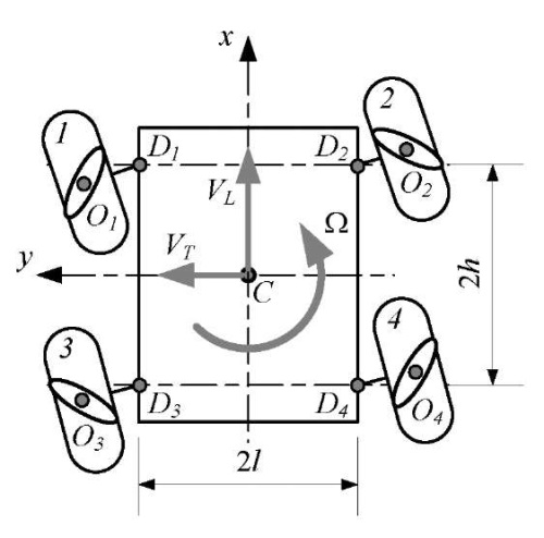
Fig. 1. Kinematic scheme of the platform
Description of the kinematic model construction method. We describe the movement of the platform within the framework of a nonholonomic formulation of the problem using a simplified model of mecanum wheels: the wheel is modeled by a disk with radius  , and the contact point can slip relative to the direction perpendicular to the axis of the contacting roller. At the same time, if there is no error in the arrangement of the wheel axles, there is a relationship between the angular speeds of rotation of the wheels around its own axis
  and the speeds of the platform
  [15]:
[15]:
 (1)
(1)
where  — angle between the direction of the axis of the contacting roller and the plane of the mecanum wheel.
To study the influence of structural errors, it is needed to describe the relationship between angular velocities of the wheels  and speeds of the platform
  taking into account the errors associated with the location of the wheel axles. The parameters of the platform design and wheel arrangement are given in Table 1.
Table 1
Platform design parameters
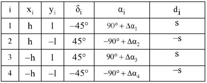
Here,
 — angle characterizing the nonorthogonality of the wheel axes and the longitudinal axis of platform
  ;
;
 — vector
  projection onto the own axis of rotation of the i-th wheel.
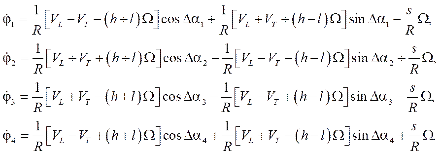
Research Results. Describing the kinematics of the mecanum platform within the framework of nonholonomic mechanics, as was done in [3–5], in the absence of structural errors ( ), , we determine the condition of nonslip of the contact point along the axis of the contacting roller:
 (2)
(2)
where  — projections of the velocity of point
  of contact of the i-th wheel with the supporting surface, which are determined from the vector equation:
 (3)
(3)
Here,
 — velocity vector of point
  of contact of the i-th wheel with the supporting surface in projections on the axis of the movable coordinate system
  ;
;
 — velocity vector of the geometric center of the platform in projections on axis ;
 — angular velocity vector of the platform in projections on axis ;
 — radius-vector connecting the geometric centers of platform
  and the i-th wheel
  , in projections on axis ;
 — angular velocity vector in projections on axis ;
 — radius-vector connecting the geometric centers of the i-th wheel
  and the contact point of roller
  .
.
Rewriting vector equation (3) and using skew-symmetric matrices to calculate vector products, we rewrite equation (3) in matrix form:
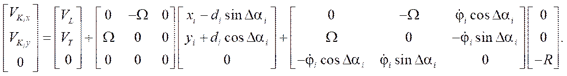 (4)
(4)
After performing calculations:
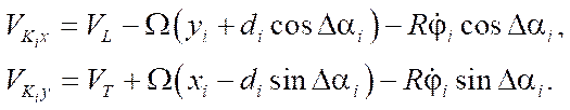 (5)
(5)
After transferring the platform parameters from Table 1 to relationship equations (2) taking into account (5), they can be represented as:
 (6)
(6)
Note that in the absence of errors in fixing the axles of the wheel motors  , equations (6) take the form:
 (7)
(7)
and coincide with the known results [6].
In matrix form, equations (6) and (7) can be represented as:
 (8)
(8)
 (9)
(9)
where
 — vector of pseudovelocities of the platform;
 — vector of angular velocities of wheels;
 — matrix of coefficients at pseudovelocities in equations (6); and
 .
.
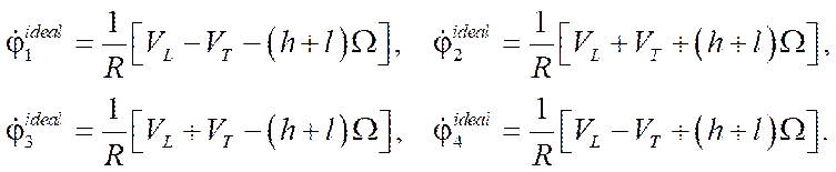
When forming the control at the kinematic level, the values of the angular velocities of platform  are calculated according to the desired values of the pseudovelocities of the platform according to the formula:
 (10)
(10)
where superscript d indicates the desired (program) speed values. The obtained values of angular velocities are fed to the input of the wheel motor control system.
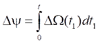
However, if there are inaccuracies in the fastening of the axles of the wheel motors, according to the results of testing the program values of the angular velocities of the wheels, the movement of the platform is realized in the form:
 (11)
(11)
According to the found expression, it is possible to estimate the error of developing the program movement of the platform, specified by the presence of inaccuracies in fixing the axles of the wheel motors, according to the formula:
 (12)
(12)
where  — unit matrix of order 3.
Since the pseudovelocities of the platform are related to the coordinates of the geometric center in a fixed reference frame by the relations [15],
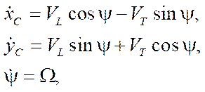 (13)
(13)
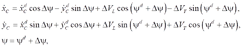
then, taking into account the errors of the pseudovelocities, we can rewrite the indicated expressions in the form:
 (14)
(14)
where
 ,
,  — laws of velocity variation of the platform geometric center in a fixed reference frame corresponding to the program movement;
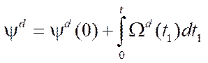 — law of the angle variation of the platform course corresponding to the program movement;
 — course angle error.
Taking into account the entered designations, we obtain formulas for positioning errors in the form:
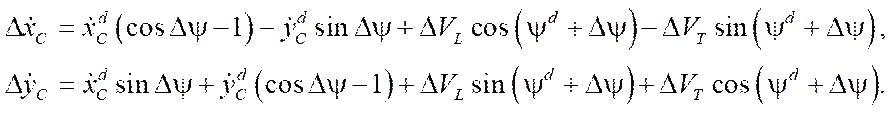 (15)
(15)
As a numerical example for error estimation, consider the parameters of the robot KUKA youBot [16]:

As an example, let us take the errors of fixing the axles of the motor wheels equal to:

Below are the results of calculating the errors of the platform velocities with simple movements of the platform. As examples of simple platform movements, consider:
 ;
; ;
; .
.The errors of the pseudovelocities of the platform with these movements are calculated using the formulas:
 ;
;
 ;
;
 .
.
The obtained values of pseudovelocity errors are significant for mobile robots with mecanum wheels, since they cause deviations in coordinates of the order of 10 cm in 2 minutes of robot movement. This makes it unacceptable for the mekanum platform to function offline in the absence of compensation for these positioning errors. Note that occurrence of a non-zero error in the angular velocity of rotation of the platform causes a nonlinear increase in the positioning error of the platform (formulas (15)) when considering control at the kinematic level.
These results allow us to conclude that it is required to take into account the inaccuracies of fixing the wheel axles when building a control system. It should be noted that since the mounting errors of the wheel motor axles are unknown quantities, it is required to develop methods for identifying the parameters of the mathematical model of robot movement to determine them [16].
The application of the developed kinematic model of the mecanum platform, which takes into account the inaccuracies of fixing the axles of the wheel motors, makes it possible to build control at the kinematic level with greater positioning accuracy.
Thus, within the framework of this study, a model of the kinematics of a mobile platform with mecanum wheels is presented with an error in the installation of the axes of the wheel motors. A formula is obtained for estimating the errors of the pseudovelocities of the platform with software control formed at the kinematic level. Errors in the development of program motion for simple movements of the mecanum platform (forward movement, lateral movement to the left, and rotation in place) have been estimated.
Discussion and Conclusion. The resulting kinematic model of a mobile platform with mecanum wheels can be used to improve positioning accuracy by forming a platform motion control that compensates for the impact of wheel installation inaccuracies. To use the obtained model in the control tasks of the mecanum platform, it is required to develop methods for identifying the parameters of the mathematical model in the future.
The task for further research in this area is to develop a mathematical model of the dynamics of the mecanum platform, taking into account the errors in the installation of the axes of the wheel motors.
1. Adascalitei F, Doroftei I. Practical Applications for Mobile Robots Based on Mecanum Wheels – a Systematic Survey. The Romanian Review Precession Mechanics, Optics & Mechatronics. 2011;40:21–29.
2. Safar MJA. Holonomic and Omnidirectional Locomotion Systems for Wheeled Mobile Robots: A Review. Jurnal Teknologi (Sciences & Engineering). 2015;77(28):91–97. https://doi.org/10.11113/jt.v77.6799
3. Hendzel Z, Rykała Ł. Modeling of Dynamics of a Wheeled Mobile Robot with Mecanum Wheels with the Use of Lagrange Equations of the Second Kind. International Journal of Applied Mechanics and Engineering. 2017;22(1):81–99. https://doi.org/10.1515/ijame-2017-0005
4. Hendzel Z, Rykała Ł. Description of Kinematics of a Wheeled Mobile Robot with Mecanum Wheels. Modeling in Engineering. 2015;57:5–12.
5. Zeidis I, Zimmermann K. Dynamics of a Four-Wheeled Mobile Robot with Mecanum Wheels. Journal of Applied Mathematics and Mechanics. 2019;99(12):e201900173. https://doi.org/10.1002/zamm.201900173
6. Adamov BI. Influence of Mecanum Wheels Construction on Accuracy of the Omnidirectional Platform Navigation (on Example of KUKA youBot Robot). In: Proc. 25th Saint Petersburg Int. Conf. on Integrated Navigation Systems (ICINS). New York City: IEEE; 2018. P. 1–4. https://doi.org/10.23919/ICINS.2018.8405889
7. Palacin J, Martinez D, Rubies E, Clotet E. Suboptimal Omnidirectional Wheel Design and Implementation. Sensors. 2021;21(3):865. https://doi.org/10.3390/s21030865
8. Kyung-Lyong Han, Oh-Kyu Choi, Jinwook Kim, Hyosin Kim, Jin S Lee. Design and Control of Mobile Robot with Mecanum Wheel. In: Proc. Int. Conf. on Control, Automation and Systems (ICCAS-SICE). New York City: IEEE; 2009. P. 2932–2937.
9. Sun Wencheng, Li Shuge, Wang Weiqiang, Zhao Pengju, Yang Renqiang. Design of Chassis and Kinematics Research of Wheeled Robot. In: Proc. IEEE 4th Information Technology, Networking, Electronic and Automation Control Conference. New York City: IEEE; 2020. P. 2405–2408. https://doi.org/10.1109/ITNEC48623.2020.9085044
10. Junpeng Shao, Tianhua He, Jingang Jiang, Yongde Zhang. Recent Patents on Omni-Directional Wheel Applied on Wheeled Mobile Robot. Recent Patents on Mechanical Engineering. 2016;9(3):215–221. https://doi.org/10.2174/2212797609666160616091009
11. Dianfeng Zhang, Guangcang Wang, Zhaojing Wu. Reinforcement Learning-Based Tracking Control for a Three Mecanum Wheeled Robot. In: Proc. IEEE Transactions on Neural Networks and Learning Systems. New York City: IEEE; 2022. P. 1–8. https://doi.org/10.1109/TNNLS.2022.3185055
12. Danwei Wang, Chang Boon Low. Modeling and Analysis of Skidding and Slipping in Wheeled Mobile Robots: Control Design Perspective. IEEE Transactions on Robotics and Automation. 2008;24(3):676–687. https://doi.org/10.1109/TRO.2008.921563
13. Yunwang Li, Shirong Ge, Sumei Dai, Lala Zhao, Xucong Yan, Yuwei Zheng, et al. Kinematic Modeling of a Combined System of Multiple Mecanum-Wheeled Robots with Velocity Compensation. Sensors. 2019;20(1):75. https://doi.org/10.3390/s20010075
14. Li Xie, Christian Henkel, Karl Stol, Weiliang Xu. Power-Minimization and Energy-Reduction Autonomous Navigation of an Omnidirectional Mecanum Robot via the Dynamic Window Approach Local Trajectory Planning. International Journal of Advanced Robotics Systems. 2018;15(1):1–12. https://doi.org/10.1177/1729881418754563
15. Adamov BI. A Study of the Controlled Motion of a Four-Wheeled Mecanum Platform. Russian Journal of Nonlinear Dynamics. 2018;14(2):265–190. https://doi.org/10.20537/nd180209
16. Adamov BI, Kobrin AI. Parametric Identification of the Mathematical Model of the Omnidirectional Mobile Robot KUKA youBot. Mechatronics, Automation, Control. 2018;19(4):251–258. https://doi.org/10.17587/mau.19.251-258
Galina V. Pankrateva, Cand.Sci. (Phys.-Math.), Associate Professor of the Department of Robotics, Mechatronics, Dynamics and Strength of Machines
14, Krasnokazarmennaya St., Moscow, 111250
Anton E. Mordin, student of the Department of Robotics, Mechatronics, Dynamics and Strength of Machines
14, Krasnokazarmennaya St., Moscow, 111250
Gasan R. Saypulaev, postgraduate student, teaching assistant of the Department of Robotics, Mechatronics, Dynamics and Strength of Machines, ScopusID
14, Krasnokazarmennaya St., Moscow, 111250
Pankrateva G.V., Mordin A.E., Saypulaev G.R. Analysis of Positioning Accuracy in Case of Design Errors in the Installation of Mecanum Wheels of the Mobile Platform. Advanced Engineering Research (Rostov-on-Don). 2023;23(4):356-364. https://doi.org/10.23947/2687-1653-2023-23-4-356-364. EDN: IQHEGM


Advanced Engineering Research (Rostov-on-Don)
ISSN 2687-1653 (Online)
Contact with: Publisher / Editorial Office of the Journal
Publisher: Don State Technical University - DSTU, Rostov-on-Don, Russia - https://donstu.ru/en/
Editor-in-Chief: Alexey N. Beskopylny, Dr.Sci. (Eng.), Professor, Vice-Rector, Don State Technical University (Rostov-on-Don, Russia)
Don State Technical University
1, Gagarin Sq., Rostov-on-Don, 344003, Russia
tel.: +7 (863) 2738-372, e-mail: vestnik@donstu.ru
16+
Processing of personal data


