


Contents
Scroll to:
https://doi.org/10.23947/2687-1653-2024-24-3-246-254
EDN: IULDLM
Scroll to:
Introduction. When drilling oil or gas wells, rock from the bottomhole is brought to the surface by drilling mud, which is cleaned of sludge by shale shakers at the first stage. Shale shakers are equipped with such a screen and create such trajectories of vibration of the frame in order to solve a dual problem: on the one hand, to provide the cleaning of the drilling mud coming from the well mouth, and on the other hand — to maintain the proper degree of cleaning. To correctly select the nomenclature of screens, it is necessary to reliably determine the throughput capacity of a shale shaker in the real-time setting. This will allow you to pre-order the required number of screens with the required cell size. Previously, studies were conducted by sieving a mixture of calibrated granules on a standard shaker or by straining mineral oil through a fixed screen. However, this does not fully correspond to the actual conditions of drilling mud screening. The objective of this article was to simulate the throughput of a drilling shale shaker under real conditions by calculating the movement of drilling mud along a vibrating screen using its previously obtained specific throughput capacity.
Materials and Methods. When creating a mathematical model of the full throughput capacity of a shale shaker, a previously known mathematical model of fluid flow in an open channel and a finite-dimensional approximation in the form of a sequence of sections of concentrated containers connected by hydraulic conductivities (by analogy with the approximation of long electrical lines and extended gas pipelines by the finite element method) were used. The fluid flow rate over the screen was determined according to Chézy law. In this case, the cross-sectional area of the flow above the screen for a specific section was specified as the arithmetic mean between the initial and final values of the drilling mud height in the corresponding section.
Results. A chain calculation scheme for sieving drilling mud was compiled. Based on the material balance, mathematical models were developed for determining the throughput and height of drilling mud above the screen: for the first section of the screen and the first nodal point of the screen; for subsequent screen sections and subsequent screen nodal points; for the last section of the screen and the last nodal point of the screen.
A mathematical model of the drilling mud movement along the shale shaker screen has been obtained, which, due to the finite-dimensional representation of this flow along n sections of the screen length, is a system of n integral equations describing concentrated tanks, and n – 1 algebraic equations describing the flow of drilling mud between tanks.
Discussion and Conclusion. The movement of drilling mud along the length of the shale shaker screen corresponds to the movement of a steady uneven flow in an open channel. However, in the first case, the volume flow along the length is variable (decreasing to zero), and in the second case, it is constant along the length. Therefore, the use of only one differential equation for steady uneven flow in an open channel is not sufficient in this case. The resulting mathematical model of the drilling mud movement along the shale shaker screen is a mathematical basis for the development of a modeling program to determine the throughput of the shale shaker for real operating conditions, i.e., for a specific drilling mud, a given screen or a given drive system of the shale shaker.
Kichkar I.Yu. Mathematical Model of Drilling Mud Movement along a Shale Shaker Screen. Advanced Engineering Research (Rostov-on-Don). 2024;24(3):246-254. https://doi.org/10.23947/2687-1653-2024-24-3-246-254. EDN: IULDLM
Introduction. The capacity of the drilling mud cleaning unit of the rig circulation system is limited by the flow rate of the circulating drilling mud, which must be cleaned properly [1]. The capacity is the volume of drilling mud sieved through the screen, and the flow rate is the volume of drilling mud that flows without sieving. The shale shaker is the first processing vessel in this unit, and it performs primary purification. Therefore, its throughput mainly determines the capacity of the entire cleaning system.
The capacity of the cleaning unit of the circulation system (CS) of a standard drilling rig should exceed the throughput of the drilling pump and be about 30-80 l/s. Insufficient capacity of the CS limits the rate of penetration [2].
The circulating drilling mud is fed to the shale shaker directly from the well mouth via a chute. There are no intermediate tanks; therefore, even if its consumption briefly exceeds the shale shaker's capacity, the drilling mud will flow through the screen into the tank waste, which will result in its loss. If the driller's assistant opens the gate valve, the raw mud will flow past the vibrating screen into the tank. This is an extremely undesirable case, since the sludge settles in the tank, preventing it from being pumped into the desander. This dramatically reduces the degree of drilling mud purification, which leads to increased drilling costs and even complications in the well [2].
The throughput of a particular shale shaker is largely determined by the size of the screen cell with which it is equipped. With a decrease in the cell size, the throughput of the shale shaker decreases significantly, but the degree of cleaning of the drilling mud increases. In practice, to prevent the solution from passing by the shale shaker, a screen with a larger cell with a large but unknown margin of throughput is installed on it [1].
The actual measurement of the throughput of the shale shaker is difficult, because after sieving through the screen, the mud flows into the tank under the shale shaker by gravity, without passing through the pipeline. Therefore, the throughput of the shale shaker was determined by indirect methods.
In [2], based on production experience, the parameters that change the throughput are indicated: an increase in the length of the screen, a decrease in the flow rate, a decrease in the angle of inclination of the screen, a change in the direction of particle movement, a decrease in the amplitude of screen vibrations, the simultaneous use of two consecutive or parallel screens. However, the authors do not provide quantitative indicators of these parameters. In [3], values of the shale shaker throughput when working with various drilling fluids are given, but the general formula is not given. In 1, only the formula for calculating the change in capacity is indicated. The problem of selecting a screen for a specific case is solved in a review by a team of American engineers2. It consists of selecting a screen with the smallest cell, at which the shale shaker would have a throughput greater than the specified one. Several methods have been developed for testing screens, but all of them are far from the operating conditions of shale shakers on drilling rigs. Thus, in the API Recommended practice 13C standard, screens are tested either by sieving a mixture of calibrated granules on a standard shaking table or by filtering mineral oil through a stationary screen. In [4], an attempt was made to analytically describe the movement of the drilling mud flow through the screen and the process of sieving it through the screen based on the Navier-Stokes equation. The simulation results do not take into account the dynamic parameters of the screening machine. These parameters are taken into account in [5], but as a parameter in question not for the drilling fluid, but for coal sludge. The amount of all the sludge removed from the total mass is relatively small [6]. Such a concentration of sludge does not have a noticeable effect on the rheology of the drilling mud [3]. Accordingly, the separation of the dewatering process given in [7] is inappropriate. A high concentration of sludge is observed in the drilling mud leaving the desanders and desilters, which is cleaned on the second shale shaker3.
From all has been said it follows that it has not yet been possible to determine the value of the drilling shale shaker capacity using theoretical studies. Therefore, the objective of this work was to model the full throughput capacity of the shale shaker based on previously conducted laboratory experiments to determine the specific capacity.
Specific throughput capacity
Previously, the team with the participation of the author developed a methodology [7], technical and software support for the experimental determination of a mathematical model of the specific throughput of a specified screen of the first shale shaker for a real drilling mud for a special shale shaker, and experimental studies were performed [8]. If all the points of the support frame located along the screen line have the same vibration trajectories, or, as they say in vibration engineering, “the orbits are homogeneous”, then it is enough to conduct one experiment. If the trajectories are nonhomogeneous, then it is enough to conduct three experiments with trajectories at the edges and in the center of the screen. In any case, the vibration trajectory parameters of the frame points of the production shale shaker must be known and implemented in the experiments.
Experimental benches of other scientists are known, e.g., in [9], a bench that creates polyharmonic trajectories of vibrations is described. This is achieved by the corresponding arrangement of the multi-speed drive system. During the experiments, even Lissajous figures were obtained [10]. The resulting best design may work less efficiently due to external actions. At the same time, the purpose of automatic control is to compensate for the negative impact of external actions. In [11], a control method is given, in [12] — the dynamic parameters of the shale shaker under control, and in [13], an example of step-by-step optimization using the Adams and Nastran modeling units is given.
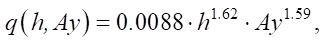
The experiments performed on sieving a bentonite-water solution with a density of 1.19 g/cm3 through a screen sample with square cells measuring 0.4×0.4 mm allowed us to obtain the following mathematical model of the specific capacity of the screen [9]:
 (1)
(1)
where q(h, Ay) — specific throughput capacity of the screen, m3/m2s; h — height of the rubble mortar layer on the screen, m; Ay — amplitude of vertical vibration acceleration, m/s2.
Boundary conditions of the sieving process
A mathematical model of specific throughput is not enough to determine the throughput capacity of a drilling shale shaker. It is also necessary to know the distribution of the height of the drilling mud layer along the length of the screen h(x) at a known flow rate of the solution entering the screen Q(0). It is not possible to take a linear distribution of height along the length of the screen as a first approximation, since the boundary condition at the end of the sieving process h(0) is unknown. The boundary condition for the beginning of the sieving process, as described earlier, is known and has the form h(0.8 ∙ L) = 0, where L — length of the screen, m.
In classical hydraulics, a mathematical model is known for the distribution of the height of the liquid layer along the length of the flow with a non-pressure steady uneven flow of liquid in an open channel [14]. However, the flow rate of the liquid in this case is constant along the length of the flow, and in our case, the flow rate decreases due to the sieving of part of the drilling mud. Therefore, the steady motion of the drilling mud flow along the shale shaker screen is an object with variables h(x) and Q(x) distributed along the length of the screen.
Analysis techniques for distributed objects
The search for engineering solutions to such problems has shown that in electrical engineering, long electric lines are replaced by a chain of concentrated resistances, capacitances and inductances [15]. Extended gas pipelines are replaced by a chain of alternating tanks and hydraulic resistances to simulate their operation [16]. This approach is especially often used in machine dynamics, where chain calculation schemes are built according to general drawings, consisting of alternating concentrated masses or moments of inertia and concentrated pliability for vibrating machines [17] and control systems [18]. This is essentially a finite element approximation of distributed objects.
Construction of a mathematical model of the full throughput capacity of a shale shaker
Let us construct a calculation scheme of the drilling mud flow from concentrated capacities and concentrated hydraulic conductivities, shown in Figure 1. To do this, we divide the length of the shale shaker screen by nodal points into equal sections of length Δx = L/m, where m — number of sections. Nodal points must be at the beginning and end of the screen. We place concentrated capacities in the nodal points. The initial and final capacities correspond to a section of the flow of length 0.5 ∙ Δx, and the remaining capacities correspond to Δx.
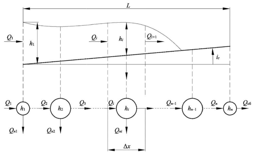
Fig. 1. Chain calculation scheme of the hydraulic system of drilling mud flow along the screen
The material balance equation for the first container in Figure 1 has the form:
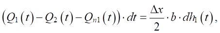 (2)
(2)
where Q1(t) — flow rate of the drilling mud entering the shale shaker, m3/s; Q2(t) — flow rate of the drilling mud flowing out of the screen from the tank of the 1st nodal point to the tank of the 2nd nodal point, m3/s; Qn1(t) — flow rate of the drilling mud sieved in the first section, m3/s; h1(t) — height of the mud layer at the first nodal point, m;
b — screen width, m.
The sieved flow rate at the first nodal point, taking into account the specific throughput, is equal to:
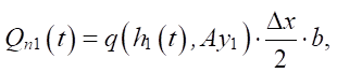 (3)
(3)
where Ay1 — vibration acceleration amplitude at the first nodal point.
Substituting expression (3) into (2) and transforming the equation, we obtain the expression for h1(t):
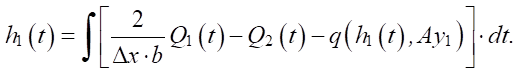 (4)
(4)
The material balance equation for the capacities of all intermediate nodal points in Figure 1 has the form:
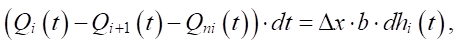 (5)
(5)
where Qi(t) — flow rate of drilling mud flowing into the tank of the i-th nodal point, m3/s; Qi+1(t) — flow rate of drilling mud flowing along the screen from the tank of the i-th nodal point to the tank of i + 1st nodal point, m3/s; Qni(t) = q(hi(t), Ay) ∙ Δx ∙ b — flow rate of drilling mud flowing along the screen from the tank of the i-th nodal point to the tank of i+1st nodal point, m3/s; hi(t) — height of the solution layer at the i-th nodal point, m.
By transforming equation (5), we obtain the expression for all intermediate nodal points:
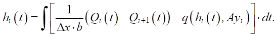 (6)
(6)
At the last nodal point, based on physical considerations, we take the height of the solution layer to be zero (C), for not to support the flow in the event of its flow into the tank waste. This is essentially the right boundary condition for the height of the solution layer. The flow rate of the drilling mud entering the shale shaker is assumed to be constant in this mathematical model and equal to the specified value Q1(t) = Q1 зад. This is an indirect assignment of the left boundary condition for the height of the solution layer.
All intermediate costs in Figure 1 are determined by the difference in heights of the solution layer hi–1(t) – hi(t) and the concentrated hydraulic resistance of the screen section. Drilling mud is a non-Newtonian fluid, but with the turbulent flow of clay solutions, it is possible to proceed from the usual formulas of hydraulics [19].
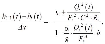
To determine the flow rate Qi(t), we do not specify the value of the hydraulic resistance of a section of the screen with a length of Δx, but we use the well-known differential equation for a steady-state non-uniform flow of constant flow rate [20], but for a raised screen:
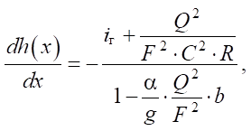 (7)
(7)
where iг — geometric slope of the flow channel, in Figure 1  ; F — cross-sectional area of the flow, m2;
C — Chézy coefficient; R — hydraulic radius of the flow cross-section, m; α — Coriolis coefficient, α = 1.10 – 1.15 [21]; g — gravitational acceleration.
Let us express the derivative in differential equation (7) by finite differences and use the variables from the calculation scheme in Figure 1 in it:
 (8)
(8)
where Fi — cross-sectional area of the flow in the section from the i – 1st nodal point to the i-th nodal point.
Here, it should be clarified that Qi(t) — flow rate in the section from the i – 1st nodal point to the i-th nodal point. The cross-sectional area of the flow in this section varies from hi–1(t) b to hi(t) b. Therefore, we define value Fi as the average value of these areas:
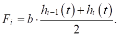 (9)
(9)
Value of the hydraulic radius of the flow is equal to the ratio [15]:
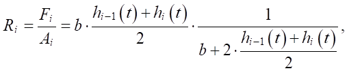 (10)
(10)
where Ai — length of the wet perimeter of the flow in the section from the i – 1st nodal point to the i-th nodal point, m.
The width of the industrial shale shaker screen is from 1 meter, the thickness of the solution layer on the screen is several centimeters [4]. Therefore, from expression (10), it follows that Ri ≈ (hi–1(t) + hi(t))/2. Substituting this value and value Fi from expression (9), we obtain:
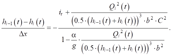 (11)
(11)
We solve equation (11) with respect to Qi(t) for i > 1:
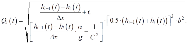 (12)
(12)
Discussion and Conclusion. The mathematical model of the flow of drilling mud through the shale shaker screen is a system of n equations (6) and n – 1equations (12).
The initial conditions for variables hi(0) cannot be taken as zero, since this will lead to division by zero in equations (12). Therefore, it is recommended to take these conditions as non-zero, but sufficiently small, e.g., hi(0) = 0.0001.
Modeling of the system of equations (6) and (12) can be performed in simulating environments, such as MATLAB with the Simulink or SimInTech application. In any case, it is required to determine the number of nodal points of the chain calculation scheme in Figure 1. The throughput capacity of a shale shaker equipped with a particular screen is equal to the flow rate Q1 зад, at which the last 20–25% of the screen length would be free of drilling mud and used to dewater the sludge4. Therefore, the penultimate nodal point with a minimum number of these points should be at the same distance from the edge of the screen. This implies Δx ≈ 0.15 ∙ L, what the seven nodal points correspond to.
In this work, the task was to determine the steady-state flow of the drilling mud, or more precisely, its profile. The author was forced to use the transient process of this flow, since it was impossible to establish the left boundary condition h1(∞), instead of which an indirect assignment of this boundary condition Q1(t) = Q1 зад was used. The final number of nodal points is determined only in the process of modeling based on the accuracy of the drilling mud profile. For this purpose, the simulation of mathematical models (6) and (12) with n and n + 1 nodal points is performed. If the greatest difference in the flow profiles exceeds, e.g., 5% of the value of the mud layer height at this point, then the number of nodal points is increased by one to n + 2 [22]. Then, a simulation is performed with n + 2-nd node points and the flow profiles of this simulation are compared to the result of the previous simulation with n + 1 points. Upon reaching the specified error, the mathematical model with the latest value of the number of node points is used in the future.
The obtained mathematical model of the drilling mud flow along the shaker screen, together with the previously obtained mathematical model of the specific throughput capacity of the screen for specific drilling mud [8], makes it possible to reasonably recommend the installation of a screen with certain cell sizes for various costs of drilling mud flowing from the well mouth.
1. American Association of Drilling Engineers Shale Shakers and Drilling Fluid System. Houston: Gulf Publishing Company; 1999. 335 р.
2. Ibid. P. 3–335.
3. Ibid. P. 3–335.
4. American Association of Drilling Engineers Shale Shakers and Drilling Fluid System. Houston: Gulf Publishing Company; 1999. 335 р.
1. Pletnev NS, Semenov NV. Analysis of Standard Designs of Vibrating Screens and Features of Their Operation. In: Proc. All-Russian Conference with International Participation with Elements of a Scientific School “Modern Problems of Hydrogeology, Engineering Geology and Hydrogeoecology of Eurasia”. Tomsk: TPU Publ.; 2015. P. 632–635. (In Russ.) URL: https://earchive.tpu.ru/bitstream/11683/18336/1/conference_tpu-2015-C109-118.pdf (accessed: 29.04.2024).
2. Bulatov AI, Proselkov YuM, Shamanov SA. Drilling Technique and Engineering of Oil and Gas Wells. Moscow: Nedra; 2003. 1007 p. (In Russ.) URL: https://www.geokniga.org/bookfiles/geokniga-bulatov-ai-proselkov-yumshamanov-sa-tehnika-i-tehnologiya-bureniya-neftyanyh-i-.pdf (accessed: 20.05.2024).
3. Ryazanov AYa. Encyclopedia of Drilling Fluids. Orenburg: Letopis'; 2004. 664 p. (In Russ.) URL: https://search.rsl.ru/ru/record/01002873248 (accessed: 20.05.2024).
4. Sansiev VG. Hydrodynamic Principles of the Drilling Mud Screening Process. Oil and Gas Studies. 2009;75(3):41–46.
5. Sansiev VG. Modeling of Coal Sludge Classification and Dehydration Processes on Screen. Mining Informational and Analytical Bulletin. 2013;(7):325–335.
6. Golovin MV, Dobik AA, Kortunov AV, Mishchenko VI. Modern Development Trends of Shale Shakers for Drilling Mud Cleaning. Drilling and Oil. 2014;(3):50–52. URL: https://burneft.ru/archive/issues/2014-03/14 (accessed: 20.05.2024).
7. Kichkar YuE, Kichkar IYu, Miller AS. Estimation of Vibration Screens Nets Specific through Capacity. RF Patent No. 2379127 C 1. 2010. 8 p. URL: https://patents.s3.yandex.net/RU2379127C1_20100120.pdf (accessed: 20.05.2024).
8. Kichkar YuE, Kichkar IYu. A Study of the Frame Vibration Parameters Influence on a Vibrating Screen Specific Capacity. Automation, Telemechanization and Communication in Oil Industry. 2017;(8):37–40.
9. Penagos HP, Gantiva ME, López JAA. Detection of Failures in the Operation of Shale Shaker Machines for the Separation of Solids In: Proc. 3rd International Conference on Electrical, Computer, Communications and Mechatronics Engineering (ICECCME). New York City: IEEE; 2023. P. 1–6. https://doi.org/10.1109/ICECCME57830.2023.10253357
10. Zhipeng Lyu, Sizhu Zhou. Design of Spatial Lissajous Trajectory Vibrating Screen. In book: Jianrong Tan (ed). Advances in Mechanical Design. Singapore: Springer; 2020. P. 493–498. https://doi.org/10.1007/978-981-32-9941-2_40
11. Kichkar YuE, Kichkar IYu, Posmitnaya LA. Method of Vibrating Sieve Drives System Control. RF Patent No. 2649203. 2018. 14 p. URL: https://patents.s3.yandex.net/RU2649203C1_20180330.pdf (accessed: 20.05.2024).
12. Osadolor AO, Bashir ME, Osifo TI. Development and Evaluation of a Small-Scale Shale Screening Machine. Nigerian Journal of Scientific Research. 2022;21(1):72–78.
13. Korostelkin AA, Filintsev AA, Novokshonov VV, Nikitin AV. On Shale Shaker’s Structural Optimization and Performance Improvement. IOP Conference Series: Materials Science and Engineering. 2020;986(1):012058. https://doi.org/10.1088/1757-899X/986/1/012058
14. Kalinin AV. Dependence of the Chézy Coefficient from Froud Number. Journal of Science and Education of NorthWest of Russia. 2019;5(3):38–56.
15. Vasileva TN, Aronov LV. The Mathematical Model of the Long-Distance Transmission Circuits Operating Regimes. Herald of Ryazan State Agrotechnological University Named after P.A. Kostychev. 2012;14(2):51–54. URL: https://vestnik.rgatu.ru/archive/2_2012.pdf?ysclid=lwz0apyfjj690751007 (accessed: 20.05.2024).
16. Meshalkin VP, Chionov AM. Computer Modeling of the Long Multilayer-Insulated High-Pressure Subsea Gas Pipeline. Matematicheskoe modelirovanie. 2017;29(8):110–122. URL: https://www.mathnet.ru/php/archive.phtml?wshow=paper&jrnid=mm&paperid=3880&option_lang=eng (accessed: 20.05.2024).
17. Blekhman II. Theory of Vibration Processes and Devices. Vibration Mechanics and Vibration Engineering. St. Petersburg: Publ. House “Ruda i metally”; 2013. 640 p. (In Russ.)
18. Kulikov VO, Breido IV. Skipping Resonant Frequencies of Vibrating Screen Using Mitsubishi Electric FR A800 Series Frequency Converter. Science: Present and Future. 2019;1:222–226. (In Russ.) URL: http://elib.kstu.kz/fulltext/temat/2019/elibrary_41177383_25140206.pdf (accessed: 20.05.2024).
19. Bulatov AI. System Analysis of Current Research Visco-Plastic Liquids – Clay and Cement Mortars (Part 1). Drilling and Oil. 2016;(3):18–23. URL: https://burneft.ru/archive/issues/2016-03/18 (accessed: 20.05.2024).
20. Baigaliev BE, Gortyshov YuF, Samoilenko AV. Investigation of the Slope Influence on Hydraulic Resistances of Trapezoidal Channels. Vestnik of Tupolev KNRTU. 2012;(2):35–43.
21. Abdyukova RYa, Habibullin MYa. Calculation of Geometric Dimensions of a Mud Pump Valve and Determination of the Plate Lifting Height. Equipment and Technologies for Oil and Gas Complex. 2015;(5):15–18.
22. Meretukov ZA, Zaslavets AA, Koshevoi EP, Kosachev VS. Methods of Solving Differential Equations of Hydrodynamics. New Technologies. 2012;(1):36–41.
Ilia Yu. Kichkar, Cand.Sci. (Eng.), Associate Professor of the Production Automation Department, Institute of Computer Systems and Information Security
2, Moskovskaya Str., Krasnodar, 350072
Kichkar I.Yu. Mathematical Model of Drilling Mud Movement along a Shale Shaker Screen. Advanced Engineering Research (Rostov-on-Don). 2024;24(3):246-254. https://doi.org/10.23947/2687-1653-2024-24-3-246-254. EDN: IULDLM


Advanced Engineering Research (Rostov-on-Don)
ISSN 2687-1653 (Online)
Contact with: Publisher / Editorial Office of the Journal
Publisher: Don State Technical University - DSTU, Rostov-on-Don, Russia - https://donstu.ru/en/
Editor-in-Chief: Alexey N. Beskopylny, Dr.Sci. (Eng.), Professor, Vice-Rector, Don State Technical University (Rostov-on-Don, Russia)
Don State Technical University
1, Gagarin Sq., Rostov-on-Don, 344003, Russia
tel.: +7 (863) 2738-372, e-mail: vestnik@donstu.ru
16+
Processing of personal data


