


Contents
Scroll to:
https://doi.org/10.23947/2687-1653-2025-25-2-142-151
EDN: LDXARH
Scroll to:
Introduction. Control of underwater robotic complexes (URC) is complicated by factors, such as inertia, stochastic disturbances, and lack of navigation infrastructure. Existing approaches to modeling and predicting URS behavior are known for their weak or absent integration of data from real sensors in real time. By eliminating this gap in integrated solutions, it is possible to combine physical models, digital twins, and visualization. A promising tool for overcoming the above limitations is a digital twin (DT), which provides an accurate digital representation of an object through the integration of data from physical sensors and mathematical models. The objective of the presented study is to develop a method for predicting the dynamics of the URC using a digital twin to improve the efficiency of autonomous control.
Materials and Methods. The basis of the study was the development of a mathematical model of the motion of an underwater robotic complex. It included differential kinematics, modeling of environmental resistance, and rotation dynamics. The following sensors were used to collect and process data: incremental encoders, a three-axis accelerometer, and a gyroscope. A proportional-integral differentiating (PID) controller was applied to control the motion along each axis. The Unity Game Environment was used to visualize and test the model. It created a digital twin module with the ability to display the system state in real time. The Arduino IDE platform was used as software for low-level programming, as well as MATLAB and Python for data analysis and graphing.
Results. To verify the model, experiments were conducted on a physical model. They were compared to the simulation of the object's behavior in a virtual environment. Graphs of discrepancies between physical and simulated trajectories were presented. Statistical metrics characterizing the accuracy of the digital twin were calculated. The maximum deviation in coordinates did not exceed 5.3 mm, the average angular deviation was 3.5°. This confirmed the reliability and practical applicability of the proposed model in autonomous control of a robotic complex. It was also found that the average error along X — 3.11 mm, along Y — 2.92 mm. The average error in angle Z — 1.8°. The response time was less than 10 ms. The stability of the digital twin to minor fluctuations in the data was provided by smoothing the input data, the stability of the system regulator, and adaptation of the model to the calibration values at the start of each cycle.
Discussion and Conclusion. Digital twins are suitable for predictive control and monitoring of an object under uncertainty. The proposed approach can be scaled for various types of robotic systems operating in aggressive and poorly predictable environments. Further research in this area may involve the introduction of adaptive and neural network control methods.
Gladyshev M.D., Rybakov A.V. Integration of Sensor Data and Mathematical Modeling of Underwater Robot Behavior Using a Digital Twin. Advanced Engineering Research (Rostov-on-Don). 2025;25(2):142-151. https://doi.org/10.23947/2687-1653-2025-25-2-142-151. EDN: LDXARH
Introduction. In recent years, there has been growing interest in digital twin (DT) technology. These are virtual models closely related to physical objects and designed to display, analyze and predict their behavior in real time [1]. DT are widely used to solve applied problems in industry, energy and transport, especially if it is necessary to control and manage objects under conditions of high uncertainty [2]. With the spread of autonomous robotic systems, the digital twin becomes an important tool for providing reliable and sustainable management. It allows for the formation of a predictive model of the object's behavior, taking into account both internal parameters and external actions [3].
Of particular interest is the use of DT in the control of underwater robotic complexes (URC), where operating conditions are significantly complicated by poor visibility, lack of precise navigation, communication delays, high inertia, and noise in sensor data. All this reduces the efficiency of traditional closed-loop control systems [4]. There are publications on digital twins in the public domain, but the topic is still insufficiently developed in terms of using DT in underwater systems. Existing studies, as a rule, either do not cover predictive control tasks or do not take into account the specificity of the underwater environment and typical sensor errors [5]. Numerous papers are characterized by significant gaps related to the lack of integrated solutions for building digital twins of underwater robotic systems focused on stable predictive control and state assessment under conditions of noisy and incomplete data.
A stable assessment of the current state of the underwater robotic complex (URC) is required, and this can be provided by integrating sensor data — accelerometry, gyroscopy, encoder measurements, and other sources. However, due to the instability and noise typical of inertial sensors, it is necessary to implement algorithms for filtering, correcting and calibrating data at different stages of operation [5].
It should also be noted that in the literature on digital modeling and control of robotic systems, authors often focus on static models or limited control scenarios (e.g., on navigation or position stabilization). At the same time, a comprehensive approach to predicting the dynamic behavior of URC using digital twins in real time has not been sufficiently developed.
Based on the aforesaid, the objective of this study is to develop and apply a method for predicting the dynamic behavior of the URC using a digital twin to improve the efficiency of controlling an autonomous system when performing underwater engineering work.
Materials and Methods. To reach the research objective, a comprehensive model was implemented, including a physicomathematical description of the motion, sensor architecture, and visualization.
Scientific research made it possible to solve the following problems:
Within the framework of the presented work:
The motion of the URC is described on the basis of differential kinematics and equations that take into account water resistance, inertial characteristics of the system, and control actions. The model is based on a system of second-order motion equations modified to take into account hydrodynamic resistance and correction coefficients obtained experimentally. Assumptions are made about the rigidity of the housing, insignificant drift, and quasi-stationary motion.
The system state vector includes coordinates: x, y, z, and heading angle θ, as well as linear and angular rates. The formulas used in the introduction describe kinematic relationships, feedback, resistance model, and control signals. PID controllers with parameters empirically selected on the basis of the system response are used for control along the longitudinal, transverse, and vertical axes.
A modular sensor system is used to collect data in real time. Its elements:
The sensor data was pre-filtered, calibrated (normalized relative to the zero position) and integrated into the digital twin model.
The key stage in building a digital twin is mathematical modeling of the movement of the underwater robotic complex. It allows predicting the behavior of the object in various environments [6]. This study considers a mobile URC with a rigid physical structure, moving in a flat (2D) or spatial (3D) coordinate system depending on the task scenario [7]. An independent drive for each of the tracks is used to control the movement, which allows for differential maneuvering [8].
To simulate the position and orientation of the URC on the plane, a kinematic model of a differential robot is used, based on the position of the center of mass (or center of geometry) of the robot [9]. Let x and y be the coordinates of the center of mass in the global coordinate system, θ — robot’s orientation angle (angle between the longitudinal axis and the OX axis in the global system).
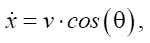 (1)
(1)
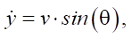 (2)
(2)
 (3)
(3)
where v — linear speed of the center of mass (determined by encoder readings); w — angular speed (obtained from a gyroscope or calculated by the difference in track speeds).
The linear and angular speeds are related to the individual speeds of the right vR and left vL tracks:
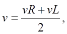 (4)
(4)
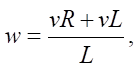 (5)
(5)
where L — robot base (distance between tracks).
The robot's behavior is significantly affected by the underwater environment: water resistance, lifting force, viscous forces, friction forces. These effects are taken into account in the form of generalized disturbance Fd(t) [10]. The system of differential equations takes the form:
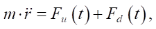 (6)
(6)
where M — robot’s mass;  — position radius vector; Fu(t) — control action from the drive system (determined by the PID controller or another algorithm); Fd(t) — environmental disturbances (determined experimentally or set empirically).
Within the framework of the layout and digital model, the resistance of the environment can be taken into account in the form of a damped term:
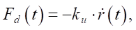 (7)
(7)
where ku — coefficient of viscous resistance of the medium (adjustable parameter of the digital twin).
The physical model is equipped with encoders, therefore the positions and orientation of the URC in space are calculated through numerical integration of the speeds obtained from the left and right tracks:
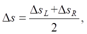 (8)
(8)
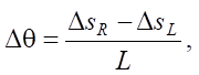 (9)
(9)
where ΔsL, ΔsR — increments of distance according to encoder readings; Δs — increment of the center of mass;
Δθ — change in orientation.
We use the current orientation Δθ, to express the new position in the global coordinate system:
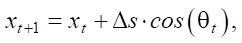 (10)
(10)
 (11)
(11)
Mathematical modeling is a fundamental part of the development of a digital twin of an underwater complex [11]. The objective of modeling is to formalize the processes of movement [12], control and response to external actions with the possibility of further analysis of the stability and accuracy of execution of control actions [13].
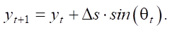
The underwater robot is considered as a system with multiple inputs and outputs, located in an environment with a high level of inertia, delay and stochastic disturbances [14]. Control actions are implemented through thrust modules, and movements are tracked using encoders and inertial measurement units [15]. The model can be described as a system of second-order equations with position and speed feedback:
 (12)
(12)
where M — mass matrix (includes inertial characteristics); D — damping matrix (taking into account viscous resistance of water); K — stiffness matrix (includes elastic forces in the case of mechanical constraints); x(t) — position and orientation vector in 3D space; u(t) — control action (signals to the motors); B — control distribution matrix.
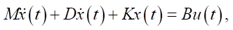
For rotational motion, the Euler model is used:
 (13)
(13)
where J — inertia tensor of the robot, ω(t) — angular speed (from the gyroscope), τ(t) — control moment.
When implementing a spot turn operation, as a rule, tracks with different directions of rotation are used. The difference in speeds on the right and left tracks sets the moment:
 (14)
(14)
To set the angle of rotation, the expression is used:
 (15)
(15)
The control system is implemented in the form of PID controllers for each axis (X, Y, Z):
 (16)
(16)
where e(t) = xreF(t) − x(t) — error between target and current position. Coefficients Kp, Ki, KD are adjusted according to the optimality criterion.
Table 1
Regulator Coefficients for Position Stabilization
|
Axis |
Kp |
Ki |
Kd |
|
X |
1.20 |
0.05 |
0.60 |
|
Y |
1.00 |
0.04 |
0.50 |
|
Z |
2.00 |
0.10 |
0.90 |
The physical model of the robot is implemented on the basis of Arduino Mega 2560 Pro. Microcontroller — ATMega 2560-16AU, 16 MHz, 256 KB FLash, with 54 digital inputs/outputs (I/O), 16 analog inputs, USB-UART interface CH340G. The complex is connected to sensors and a drive control system. Data is collected and transmitted to the digital environment via Serial port in the format of combined time-stamped lines.
The virtual implementation of the digital twin is created in Unity. C#-scripts are used to interpret the data, display the movements, rotations and behavior of the object in a three-dimensional environment. Axes, contours, coordinate values and trajectories are visualized. A model of a translucent robot that does not interact with other objects is used, which allow us to concentrate on comparing movements.
A data processor and a filtering system are implemented on the Unity side. Integration with correction based on sensor data is applied to calculate angles and coordinates. Individual blocks are implemented as scripts with the ability to scale the project. Standard metrics are used to statistically assess accuracy: standard deviation, maximum deviation, and average error in coordinates and angles.
Research Results. To verify the model in a digital environment, movements were simulated under successive control actions. Then, the trajectories of rectilinear and semicircular motion were compared (Fig. 1 and 3). The readings of the digital robot were compared to the ideal trajectory. The root-mean-square analysis showed a discrepancy when moving in a straight line (Fig. 2) and in a semicircle (Fig. 4).
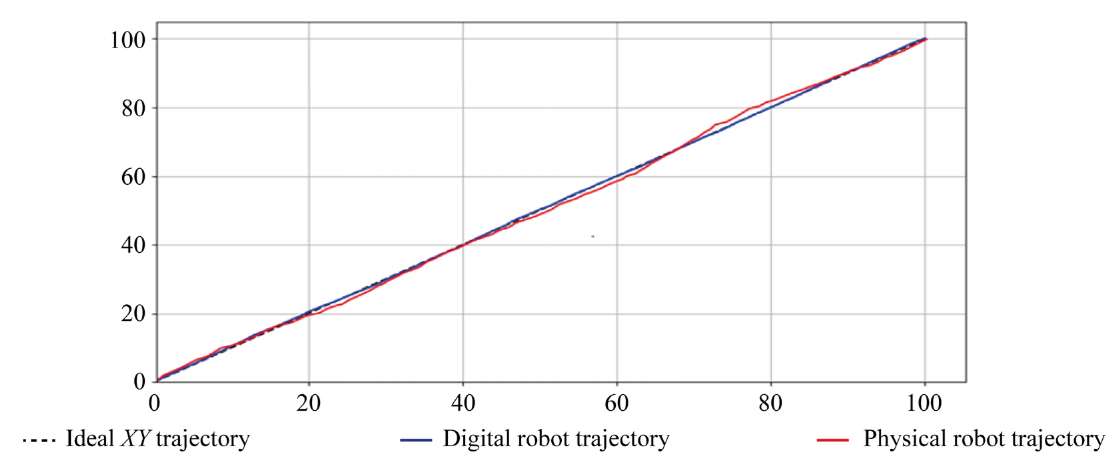
Fig. 1. Trajectories of motion in a straight line
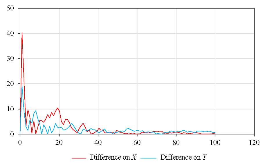
Fig. 2. Error (%) when measuring on a straight line
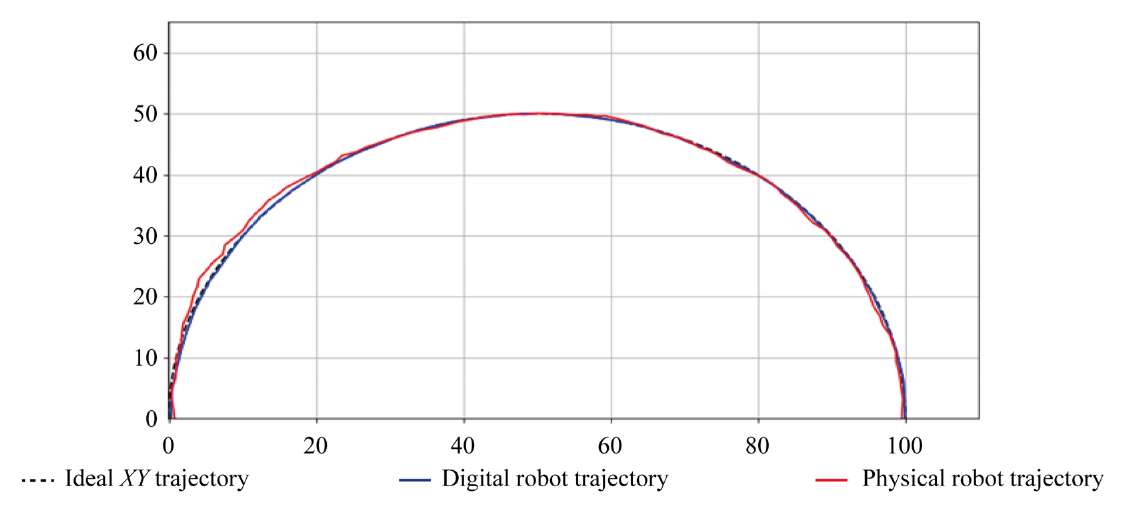
Fig. 3. Trajectories of movement in a semicircle
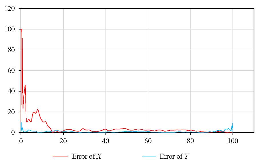
Fig. 4. Error (%) when measuring on a semicircle
The quality of displaying the URC behavior in the digital twin was assessed during experiments that included linear motion, the spot turn, and the trajectory with turns. In parallel, data from real sensors was recorded and compared to the parameters of the model in Unity. The results of measurements and comparisons are presented in Table 2.
Table 2
Deviation Indicators
|
Metric |
Value |
|
Maximum deviation of X |
5.3 mm |
|
Maximum deviation of Y |
4.8 mm |
|
Average angular deviation |
3.5о |
The digital twin was visualized in the Unity environment. This flexible 3D engine allowed us to embed data streams from physical sensors, display spatial movements, orientation, and also create scenarios for interaction with the external environment (Fig. 5).
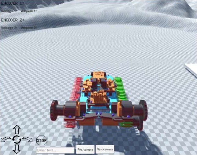
Fig. 5. Robotic complex control program
Data from physical sensors (accelerometers, gyroscopes, encoders) was transmitted via a COM port (communications port) using a custom script in C#. Incoming data was divided into channels and displayed as parameters of the twin object.
The digital model in Unity used the same coordinate system and the same control structure as the implemented mathematical model. Its functions were:
The solution allows creating a closed loop “model – reality – visualization” and provides consistency between the digital twin and the physical system (Fig. 6).
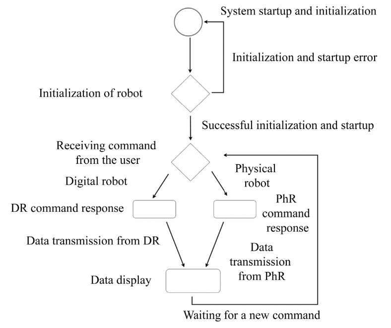
Fig. 6. Software operation algorithm: DR — digital robot, PhR — physical robot
The elements of the software operation algorithm are listed below.
System Startup and Initialization. The physical robot is turned on and connected via USB to a computer that collects and analyzes data, runs the main program, and initializes additional scripts:
All this takes place in Unity, after which the system is ready for work.
Robot Initialization. After the program is launched, its connection with the physical robot is established. Consequently, calibration occurs, and then the sensors and modules are launched: gyroscope, accelerometer, encoders, voltmeter, ammeter. A control message about the robot's readiness for launch and the start of data transmission is sent to Unity. After that, the stage of waiting for commands starts.
Receiving Command from the User. The value of the user interface entered into the program is analyzed and processed. The message is passed to intermediate scripts to perform the actions of the digital and physical robots.
Digital Robot’s Command Response. The entered values and actions are recorded in the computer memory. Based on the embedded command execution algorithms and a mathematical model, the digital robot moves in digital space. At the same time, data on its position, speed and distance traveled, are recorded. After executing the command, the robot maintains its position and orientation in space.
Physical Robot’s Command Response. Data is transmitted to the Arduino Mega microcontroller. Here, it is analyzed and, depending on the entered command and value, scripts are activated that are responsible for the operation of sensors: left and right encoders, accelerometers, and gyroscopes. Only after that does movement start at the user's command. During the execution of the command, the robot records its position and orientation in space and transmits data to the user interface program, where the data is visualized using a 3D model linked to the physical robot.
Data Collection and Display. At this stage, data on position, tilt angles, distance traveled and other parameters are collected from the digital and physical robots and visualized in the user interface program. After that, the program waits for a new command.
The described algorithm is based on the classical principles of closed-loop feedback control systems. The use of data from sensors (accelerometers, gyroscopes, encoders) allows for the implementation of a measuring element in the general structural form of control systems. The mathematical model integrated into Unity acts as an observer, tracking the behavior of the system and providing visual verification of the correctness of command execution.
The system is designed taking into account:
Formulas (17)–(19) present the indicators that are used to analyze the accuracy of the digital twin.
Absolute position error (in mm):
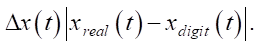 (17)
(17)
Root mean square orientation error (in degrees):
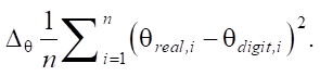 (18)
(18)
Percentage deviation of the final position:
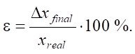 (19)
(19)
As a result of experiments and analysis of sensor readings, additional parameters are obtained that characterize the error of the developed system (Table 3).
Table 3
Detected Errors in the System
|
Parameter |
Value |
|
Mean error on Х |
3.11 mm |
|
Mean error on Y |
2.92 mm |
|
Average error of angle Z |
1.8о |
|
Maximum deviation |
5.3 mm |
|
Reaction time |
<100 ms |
The digital twin is resistant to minor fluctuations in the data due to the following factors:
Discussion and Conclusion. A model of a digital twin of a robotic complex based on the integration of sensor data, mathematical modeling and 3D visualization has been developed and experimentally confirmed. Sustainable control and tracking of the behavior of the robotic complex have been implemented. The results of the comparative analysis of the digital model and the real system are presented. The results of the comparison have proven:
The constructed model makes it possible to adequately assess the current state and predict the behavior of the URC under uncertainty. PID controllers provide stability during control, and visualization in Unity makes it possible to implement a digital twin as an interface for interaction with the system. Further development of this solution may be related to the implementation of adaptive and neural network control methods.
1. Meshkov AV, Gromov VS. Adaptive Nonlinear Motion Parameters Estimation Algorithm for Digital Twin of MultiLink Mechanism Motion Trajectory Synthesis. Scientific and Technical Journal of Information Technologies, Mechanics and Optics. 2022;22(5):889–895. https://doi.org/10.17586/2226-1494-2022-22-5-889-895
2. Kubrikov MV. Digital Twin in the System of External Adaptive Control of Robot Manipulators. Spacecrafts & Technologies. 2023;7(2):171–176. https://doi.org/10.26732/j.st.2023.2.10
3. Kuzmenko VP, Soleniy SV. Development of a Digital Twin Model for a Hybrid Production Line for LED Lighting Devices Assembly. Journal of Instrument Engineering. 2022;65(10):725–734. https://doi.org/10.17586/0021-3454-2022-65-10-725-734
4. Jingsong Fan, Xiangqiang Zhong, Zhimin Di, Huajie Fang. Collaborative Operation of 6-DOF Industrial Robot Based on Digital Twin. Journal of Physics: Conference Series. 2022;2206(1):012019. https://doi.org/10.1088/1742-6596/2206/1/012019
5. Farhadi A, Lee S, Hinchy EP, O'Dowd N, McCarthy CT. The Development of a Digital Twin Framework for an Industrial Robotic Drilling Process. Sensors. 2022;22(19):7232. https://doi.org/10.3390/s22197232
6. Qinglei Zhang, Run Xiao, Zhen Liu, Jianguo Duan, Jiyun Qin. Process Simulation and Optimization of Arc Welding Robot Workstation Based on Digital Twin. Machines. 2023;11(1):53. https://doi.org/10.3390/machines11010053
7. Hang Wu, Zhaoming Liu, Long Cui, Lirong Guan, Hongwei Wang. Digital Twin of Non-Ferrous Metal Casting Robot. In book: M Chen, et al (eds). Advances in Machinery, Materials Science and Engineering Application. Amsterdam: IOS Press; 2022. 760 p. https://doi.org/10.3233/ATDE220502
8. Chancharoen R, Chaiprabha K, Wuttisittikulkij L, Asdornwised W, Saadi M, Phanomchoeng G. Digital Twin for a Collaborative Painting Robot. Sensors. 2022;23(1):17. https://doi.org/10.3390/s23010017
9. Banic MS, Simonovic M, Stojanović L, Rangelov D, Miltenovic A, Perić M. Digital Twin Based Lightweighting of Robot Unmanned Ground Vehicles. Facta Universitatis. Series: Automatic Control and Robotics. 2022;21(3):188. https://doi.org/10.22190/FUACR221121015B
10. Xin Liu, Du Jiang, Bo Tao, Guozhang Jiang, Ying Sun, Jianyi Kong, et al. Genetic Algorithm-Based Trajectory Optimization for Digital Twin Robots. Frontiers in Bioengineering and Biotechnology. 2022;9:793782. http://doi.org/10.3389/fbioe.2021.793782
11. Garg G, Kuts V, Anbarjafari G. Digital Twin for FANUC Robots: Industrial Robot Programming and Simulation Using Virtual Reality. Sustainability. 2021;13(18):10336. http://doi.org/10.3390/su131810336
12. Đoàn Thanh Xuân, Tran Van Huynh, Thanh-Hung Nguyen, Vu Toan Thang. Applying Digital Twin and MultiAdaptive Genetic Algorithms in Human–Robot Cooperative Assembly Optimization. Applied Sciences. 2023;13(7):4229. http://doi.org/10.3390/app13074229
13. Sichao Liu, Xi Vincent Wang, Lihui Wang. Digital Twin-Enabled Advance Execution for Human-Robot Collaborative Assembly. CIRP Annals — Manufacturing Technology. 2022;71(1):25–28. http://doi.org/10.1016/j.cirp.2022.03.024
14. Kibira D, Weiss BA. Towards a Digital Twin of a Robot Workcell to Support Prognostics and Health Management. In: Proc. 2022 Winter Simulation Conference at Singapore. New York: IEEE; 2022. P. 2968–2979. http://doi.org/10.1109/WSC57314.2022.10015371
15. Xuan Liu, He Gan, Ying Luo, YangQuan Chen, Liang Gao. Digital-Twin-Based Real-Time Optimization for a Fractional Order Controller for Industrial Robots. Fractal and Fractional. 2023;7(2):167. http://doi.org/10.3390/fractalfract7020167
Mikhail D. Gladyshev, postgraduate student majoring in Systems Analysis, Control and Information Processing, Statistics
20a, Tatishcheva Str., Astrakhan, 414056
Alexey V. Rybakov, Cand.Sci. (Phys.-Math.), Associate Professor of the Department of Information Technologies, Associate Professor of the Department of Materials Technology and Industrial Engineering
20a, Tatishcheva Str., Astrakhan, 414056
A method for predicting the dynamics of an underwater robotic complex is developed. A digital twin system that integrates sensor data and mathematical modeling is presented. Experiments are conducted that confirm the high accuracy and stability of the model under uncertainty. Visualization in Unity improves interaction with the system and allows for comparative analysis. The results show the potential of using digital twins for autonomous systems in complex environments.
Gladyshev M.D., Rybakov A.V. Integration of Sensor Data and Mathematical Modeling of Underwater Robot Behavior Using a Digital Twin. Advanced Engineering Research (Rostov-on-Don). 2025;25(2):142-151. https://doi.org/10.23947/2687-1653-2025-25-2-142-151. EDN: LDXARH


Advanced Engineering Research (Rostov-on-Don)
ISSN 2687-1653 (Online)
Contact with: Publisher / Editorial Office of the Journal
Publisher: Don State Technical University - DSTU, Rostov-on-Don, Russia - https://donstu.ru/en/
Editor-in-Chief: Alexey N. Beskopylny, Dr.Sci. (Eng.), Professor, Vice-Rector, Don State Technical University (Rostov-on-Don, Russia)
Don State Technical University
1, Gagarin Sq., Rostov-on-Don, 344003, Russia
tel.: +7 (863) 2738-372, e-mail: vestnik@donstu.ru
16+
Processing of personal data


