Contents
Scroll to:
https://doi.org/10.23947/2687-1653-2026-26-2-2288
EDN: KDYBZG
Scroll to:
Introduction. Improving the efficiency of arc surfacing with a consumable electrode is one of the key vectors in the development of modern manufacturing. Split-arc gas-shielded welding with a consumable electrode is of particular interest. The electrode arrangement in this welding process affects the fusion zone, namely its shape and curvature. The shape of the penetration zone significantly affects the property gradient and the operational reliability of the coating. The effect of the electrode arrangement on the curvature of the penetration front remains quantitatively unassessed. The objective of this study is to quantitatively evaluate and determine the correlation of the curvature of the penetration shape depending on the relative arrangement of the electrodes.
Materials and Methods. The effect of electrode positioning on the penetration shape was studied by building up six layers and subsequently analyzing the fusion shape in the base metal. The selected influencing parameters were the interelectrode distance (z) and the electrode inclination angle (α). The surfacing process was performed in an Ar/CO₂ shielding gas atmosphere in a ratio of 98/2%. To make the fusion zone visible, the transverse cross-sections of the layers were subjected to etching. The fusion zone boundaries were digitized. A 6th-degree polynomial was used to determine the functions describing the penetration shape. The obtained functions were differentiated to analyze the fusion shape. The first-order derivative was used to determine the number of extremes. To assess the curvature of the penetration shape, the average value of the absolute second derivative was calculated over the range of values within the layer width. Correlation was established using Pearson's method.
Results. As a result of the conducted experiment, a quantitative assessment of the curvature of the penetration shape depending on the relative arrangement of the electrodes was performed. Functions describing the penetration shapes were determined. The curvature of the obtained shapes and the number of extremes were calculated. Correlation coefficients between the interelectrode distance, the electrode inclination angle, the penetration curvature, and the number of extremes were determined. It was found that the curvature of the penetration shape and the number of extremes weakly depend on the interelectrode distance. The electrode inclination angle determines the penetration curvature to a greater extent. A damping effect of the heat flux of the electric arc by the volume of the weld pool was identified at an interelectrode distance of 15 mm.
Discussion. In each experiment, the base metal fusion zone displayed a saddle-shaped geometry. Increasing the electrode included angle resulted in a shallower penetration shape, attributed to an alteration in the vector of electromagnetic forces that govern plasma streams and molten metal droplet transfer. The damping effect occurred because reducing the interelectrode distance enlarged the weld pool. A layer of molten metal, possessing high heat capacity but low thermal conductivity, separated the electric arc from the base metal, thus damping the heat flux from the arc.
Conclusion. The conducted study made it possible to quantitatively assess the effect of the electrode arrangement on the curvature of the penetration shape, as well as to determine the degree of influence of the interelectrode distance and the electrode inclination angle on the curvature of the penetration shape. The interelectrode distance was found to have a weak effect on both the fusion shape curvature and the number of extremes. The correlation coefficients for these parameters were –0.22 and 0.43. The effect of the electrode inclination angle on both the fusion shape curvature and the number of extremes was considered substantial. The correlation coefficients for these parameters were –0.65 and –0.71. As the angle of inclination of the electrodes relative to the vertical increased, the curvature of the penetration shape decreased.
Skoblikov I.P., Sapozhkov S.B. Quantitative Evaluation of Fusion Zone Curvature Correlation with Electrode Positioning in Shielded Gas Split-Arc Surfacing. Advanced Engineering Research (Rostov-on-Don). 2026;26(2):2288. https://doi.org/10.23947/2687-1653-2026-26-2-2288. EDN: KDYBZG
Introduction. In the current era of industrial development and additive manufacturing, improving the productivity of manufacturing processes is key to competitiveness, as it reduces cycle times and lowers product costs. These processes include the application of metal coatings using gas-shielded metal arc welding (GMAW) [1]. It is known that boosting the deposition rate of this welding process through higher wire feed speeds results in increased arc energy. This, in turn, causes deeper penetration into the base metal, along with spatter, undercutting, and the expulsion of alloying elements.
An alternative strategy for enhancing the deposition rate of this welding process exists. Instead of raising the wire feed speed, this approach increases the number of wires delivered to the weld pool. Paper [2] reports the outcomes of investigations into this method. One conclusion is that adding more wires to the welding system yields an exponential productivity gain, owing to more efficient utilization of the arc thermal energy.
Split-electrode surfacing is a multiwire surfacing method developed on the basis of the aforementioned approach. The essence of this method is that not one, but several filler wires are fed through the current lead. The current lead is connected to a single current source [3]. Surfacing by this method is used to solve problems related to the application of anticorrosion and wear-resistant coatings or the repair of components.
When depositing anticorrosion coatings, minimal base metal penetration with a uniform fusion line is required. This penetration characteristic provides a minimum content of the base metal in the deposited layer. In [4], the influence of the type of current on the shape of penetration during surfacing with a split electrode under a flux layer is studied. The effect of the distance between the electrodes on the shape of penetration is indirectly presented. The study notes that when surfacing with an interelectrode distance of 10–12 mm, a saddle-shaped penetration is formed. However, this penetration shape is acceptable for anticorrosion surfacing, provided no fusion defect exists at the saddle top, and the base metal content stays within 15–25%. The study does not assess the curvature of the penetration shape or establish a correlation between it and the relative position of the electrodes.
The authors of article [5] note that when applying wear-resistant coatings, the use of a curved penetration shape provides more reliable adhesion of the layers to the base metal, in contrast to a flat penetration shape. In [6], devoted to a comprehensive study of penetration shapes in various arc surfacing methods, it is emphasized that the curvature of the penetration shape determines the nature of the transition of the deposited metal to the base metal, which affects the stress concentration in the deposited metal, determines the gradient of mixing of the base metal in the deposited metal, and affects the properties of the deposited metal.
The authors [7] successfully applied the double-wire surfacing method to additive manufacturing. This makes the method attractive for repairs and additive manufacturing, where layer-to-layer metal transfer behavior is crucial. Thus, it can be concluded that, when solving problems related to the application of functional coatings, one of the quality parameters is the morphology of the base metal penetration zone.
The impact of the relative positioning of the electrodes on the penetration shape is due to changes in the electromagnetic forces in the arc gap and the characteristics of heat and mass transfer. In exploring this topic, the authors analyzed a number of studies devoted to the processes occurring in the arc gap during surfacing by this method. In [8], the forces acting on the droplet and molten metal under surfacing with a consumable electrode with a pulsed power supply were determined, and in [9], the change in these forces within two adjacent electrodes was described. It was established that when the electrodes were located close together, the droplet of molten metal and the plasma flow were affected by the Lorentz force directed into the interelectrode space. This force changes the droplet trajectory and lowers arc pressure. Paper [10] describes the process of modeling the heat distribution in an electric arc arising on a split electrode, and it is found that the heat distribution in a split arc depends on the distance between electrodes and the current strength. At certain values of current strength and interelectrode distance, the thermal field in the electric arc takes on a single-peak or double-peak structure. This heat flux distribution is an important factor that determine the shape of the penetration.
In [11], two key parameters of electrode positioning that affect the weld penetration shape are identified. These parameters are the electrode angle relative to the vertical and the distance between the electrodes. Thus, it is found that when selecting the optimal welding mode, it is required to determine not only the current strength but also the electrode positioning. This conclusion is consistent with the conclusion reached by the authors of article [10]. In [12], it has been found that the inclination angle of the working head affects the deposited layer morphology in forehand surfacing. The optimal inclination angle was found to be in the range of 10 to 30°. With this head position, it was possible to obtain layers 25 mm wide with a base metal content of 30–33%. The distance between the electrodes was 6 mm. Inconel 625 wire was used as the electrodes. Surfacing was performed under a flux layer.
From the analysis of the literature on this subject, it may be concluded that investigating the fusion shape in split-arc gas-shielded welding is of high relevance for applying functional coatings, repairing parts, and additive manufacturing. The relative positioning of the electrodes during surfacing by this method significantly affects the forces acting in the arc gap and the heat and mass transfer of the electrode metal. The change in the penetration shape depending on the distance between the electrodes and the angle of inclination of the electrodes for such a surfacing process has not been fully studied. The identified knowledge gap is the absence of quantitative data relating penetration shape to electrode spacing and inclination angle with respect to the vertical plane. Therefore, the objective of this study is to quantify and determine the correlation between penetration shape curvature and electrode relative positioning. To achieve this goal, the following tasks must be addressed:
Materials and Methods. To assess the curvature of the penetration shape depending on the electrode positioning, flat layers were deposited with different distances between the electrodes and the angle between them. The working tool was moved using a Fanuc 120iD robot (Japan). The electric arc was powered from a pulsed power supply EWM Titan XQ500 (Germany). The surfacing head consisted of two burners mounted on an adjustable bracket. The substrates used were St3 (GOST 380- 2005) steel plates, measuring 150x70x20 mm. Surfacing was performed in GMAW-Pulse mode using Sv-08G2S (GOST 2246-70) wire with a diameter of 1.2 mm. The chemical composition of the wire is presented in Table 1. A mixture of Ar (98%) and CO₂ (2%) was used as a shielding gas. This gas mixture, compared to mixtures with a higher CO₂ content, has a reduced oxidizing capacity, resulting in fewer nonmetallic inclusions under surfacing. To visualize the macrostructure of the deposited layer, samples were electrolytically etched in a sodium chloride (NaCl) solution with a concentration of 200 g/L. Before etching, the samples were polished. Etching was performed at a current density of 7–10 A/dm². A 12Kh18N10T (GOST 5632-2014) steel rod with a swab attached to the end served as the cathode. Etching was performed through rubbing the sample until the structure was revealed. This etching method was selected as one of the available methods at the time of the study. Penetration shape measurements were performed using Digimizer software (version 6.5.1).
Table 1
Chemical Composition of Wire Sv-08G2S (GOST 2246-70) (wt.%)
C | Si | Mn | P | S | Ni | Cr | Cu |
0.05–0.11 | 0.70–0.95 | 1.80–1.90 | ≤0.030 | ≤0.025 | ≤0.025 | ≤0.020 | ≤0.025 |
The distance between the electrodes (z) and their angle of inclination (α) relative to the vertical plane were selected as independent factors determining the relative positioning of the torches. During the experiment, surfacing was performed with a uniform overhang (SO) of 20 mm. Figure 1 shows the electrode arrangement under surfacing and the parameters studied.

Fig. 1. Layout diagram [11]
The layers were deposited at a wire feed speed (WFS) of 6.5 m/min for a single torch. Since two torches were used during the deposition process, the total wire feed speed was 13 m/min. The working tool moved at a constant linear speed (TS) of 4 mm/s. During the deposition process, current (I) and voltage (U) were recorded using the ammeter and voltmeter integrated into the power source. During the experiments, identical substrates were used to maintain a similar thermal pattern. Before depositing the layer, the substrates were cleaned to a metallic luster and preheated to a temperature (MPT) of 150 °C. Preheating was performed with a gas torch to simulate actual process conditions under which production work is carried out. Temperature monitoring was performed with a HIKMICRO B20 thermal imager (China). The shielding gas flow rate for each torch was 15 l/min. The total gas flow rate was 30 l/min. Table 2 shows the deposition mode.
Table 2
Surfacing Mode
WFS, m/min | I, А | U, В | TS, mm/s | MPT,°С | SO, mm | Gas, l/min |
13 | 420 | 25 | 4 | 150 | 20 | 30 |
The experimental design included six runs with different z (1Cr, 18, 21 mm) and α (5°, 10°) parameters. Samples for analysis were collected from a section comprising 3/4 of the deposited layer length. The experimental design is presented in Table 3. Figure 2 shows a photograph of a sample with its dissection line.
Table 3
Experimental Design
Run | z, mm | α, ° |
1 | 15 | 5 |
2 | 18 | 5 |
3 | 21 | 5 |
4 | 15 | 10 |
5 | 18 | 10 |
6 | 21 | 10 |

Fig. 2. Appearance of the sample
To assess the influence of the relative positioning of the electrodes on the penetration shape, its boundaries were determined in the Digimizer program. Figure 3 shows a photograph of macrosections with the boundaries outlined.

Fig. 3. Photo of macrosections with outlined boundaries [5]
Since during split-arc surfacing two heat sources are located symmetrically relative to the motion vector, the shape of the penetration is conditionally symmetrical. To assess the penetration shape, it was decided to mirror and superimpose the measured values on each other relative to the layer axis, and invert the values along the Y axis. Figure 4 shows this technique. As a result of the operation performed, it was possible to present the data as points in the XY, where X — the width of penetration from the layer axis, and Y — the depth of penetration. Moreover, the Y axis is the axis of the deposited layer.

Fig. 4. Data processing
To assess the curvature of the penetration shape based on the measured data, the regression function of each profile was determined. A sixth-degree polynomial was used to describe all curves. The first derivative of the equations describing the form of penetration was used to determine the number of extremes. The second derivative was used to quantify curvature. The curvature of the penetration shape for each experiment was calculated as the average value of the modulus of the second derivative for points lying within the layer width. The correlation between the curvature of the penetration shape and the extremes depending on the distance between the electrodes and the angle of their inclination was calculated by the Pearson method.
Research Results. Regression equations describing the shape of the penetration were determined. The coefficient of determination was greater than 0.9. The equations are presented in Table 4.
Table 4
Regression Equations
No. | X^6 | X^5 | X^4 | X^3 | X^2 | X^1 | Const | R² |
515 | –0.000075 | 0.002839 | –0.0385 | 0.216 | –0.41 | 0.15 | 0.83 | 0.91 |
1015 | –0.000003 | –0.000049 | 0.0039 | –0.050 | 0.17 | 0.16 | 0.75 | 0.90 |
518 | –0.000070 | 0.002942 | –0.0449 | 0.296 | –0.77 | 0.46 | 1.87 | 0.93 |
1018 | –0.000013 | 0.000466 | –0.0058 | 0.027 | –0.04 | –0.02 | 2.08 | 0.92 |
521 | –0.000035 | 0.001672 | –0.0292 | 0.222 | –0.67 | 0.60 | 1.02 | 0.92 |
1021 | –0.000052 | 0.002405 | –0.0413 | 0.315 | –0.99 | 1.00 | 0.65 | 0.92 |
Figure 5 shows graphs illustrating the shape of the penetration and the pattern of its change depending on the angle of inclination of the electrodes at the same distance between them. Figure 6 shows graphs describing the shape of the penetration and the pattern of its change depending on the distance between the electrodes for experiments with a fixed angle of inclination.

Fig. 5. Penetration shape and behavior for an angle of 5 and 10°:
a — for z = 15 mm; b — for z = 18 mm; c — for z = 21 mm

Fig. 6. Penetration shape and behavior at Z = 15, 18, 21 mm:
a — angle of inclination of electrodes 5°; b — angle of inclination of electrodes 10°
It can be seen from the graphs that all experiments exhibit a curved, saddle shape of penetration. Depending on the electrode arrangement, the penetration profiles display either one or two extremes.
Graphs illustrating how the curvature of the penetration shape varies with electrode positioning are shown in Figure 7. The digits 1 and 2 denote the number of extremes present on the penetration shape curve.
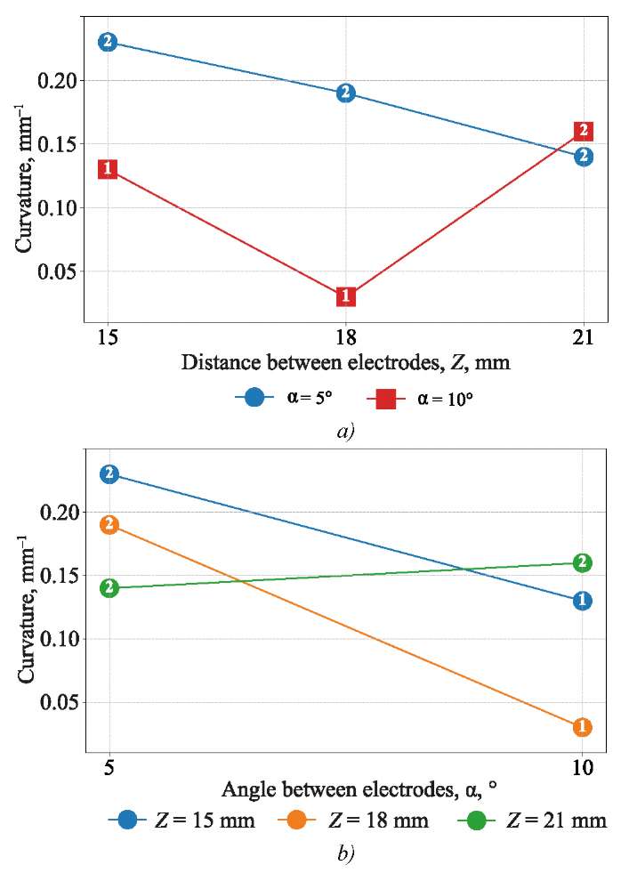
Fig. 7. Graphs of the dependence of the curvature of the fusion zone:
a — on the distance between the electrodes;
b — on the angle between the electrodesα°
For experiments with an interelectrode distance of 21 mm, the curvature of the penetration shape lies in the region of 0.15 mm⁻¹. The fusion zone has two extremes. For experiments with a distance between electrodes of 18 and 15 mm, the amount of curvature of the penetration shape depends on the angle of inclination of the electrodes. At an inclination angle of 10°, the penetration shape has a curvature of 0.03 mm⁻¹ and 0.14 mm⁻¹, respectively. The number of extremes is equal to one. As the angle decreases to 5°, the curvature increases to 0.19 mm⁻¹ and 0.24 mm⁻¹, respectively. The number of extremes becomes equal to two.
Table 5 shows the matrix obtained during the evaluation of the correlation value of the curvature of the penetration shape and the number of extremes depending on the distance between the electrodes and their angle of inclination.
Table 5
Correlation Matrix
Z | α | Curvature | Extremes | |
Z | 1 | –0.08 | –0.22 | 0.43 |
α | –0.08 | 1 | –0.65 | –0.71 |
Curvature | –0.22 | –0.65 | 1 | 0.36 |
Extremes | 0.43 | –0.71 | 0.36 | 1 |
The correlation coefficient of the distance between the electrodes with the curvature of the penetration shape is –0.22, and with the number of extremes — 0.43. The correlation coefficient of the slope angle with the curvature of the penetration shape is –0.65, and with the number of extremes — –0.71.
Discussion. The penetration shape of the base metal is characterized by the presence of an axial zone (P1) and a primary zone (P2) of penetration. The primary zone of penetration is formed directly under the action of the heat source. The formation of the axial zone of penetration is caused by the superposition of thermal fields from each heat source and the thermal effect of plasma flows rushing into the area between the electrodes [13]. Figure 8 shows a schematic representation of the fusion zone during split-arc surfacing.

Fig. 8. Schematic representation of the fusion zone during surfacing with a split electrode
The analysis of the penetration shape curvature shows that at an interelectrode distance of 21 mm, it is independent of the electrode inclination angle. When surfacing with this electrode positioning, the electric arcs behave as independent heat sources. This is evidenced by the similar penetration shape, a shape curvature value of approximately 0.15 mm⁻¹, and an equal number of extremes. As the interelectrode distance decreases to 18 or 15 mm, the penetration shape curvature becomes dependent on the electrode inclination angle. With increasing electrode inclination, penetration becomes flatter. This is evidenced by a decrease in penetration shape curvature and the number of extremes. For tests with an 18 mm electrode spacing, penetration curvature decreases by 84%, while for tests with a 15 mm electrode spacing, it decreases by 42%.
According to the results of the correlation assessment, the relationship between the interelectrode distance (z) and the curvature of the penetration shape is weak (Pearson's coefficient r = –0.22), and the relationship between the interelectrode distance and the number of extremes is moderate (r = –0.43 The correlation between the electrode inclination angle (α) and the curvature of the penetration shape is determined as moderate, close to strong (r = –0.65), while the correlation of the inclination angle with the number of extrema is estimated as strong (r = –0.71).
The change in the curvature of the penetration shape depending on the relative positioning of the electrodes is associated with a change in the vector of forces acting on the droplet in the arc. The forces acting on the droplet during GMAW surfacing were analyzed in [14]. When the droplet detaches, it is acted upon by gravity, electromagnetic force, and the force caused by the plasma flows. During split-electrode welding, the interaction of electromagnetic fields from adjacent arcs generates a Lorentz force that deflects the arc column and droplet toward the weld axis [15]. As a result, the molten metal droplets fall not directly under the electrode, but with a shift toward the weld axis. This is confirmed by the results of high-speed video recording of the tandem welding process, presented in [16]. This shift results in the formation of a shallower penetration shape.
Notably, the minimum penetration curvature, equal to 0.03 mm⁻¹, occurs at an interelectrode distance of 18 mm and an inclination angle of 10° to the vertical. As the electrodes approach 15 mm, the penetration shape becomes steeper, despite the closer heat sources and the increased radial component of the electromagnetic force.
A comparison of the experimental results shows that when surfacing with the parameter z = 15 mm, the width of the deposited layer is smaller. However, due to the equal volume of molten electrode material, the thickness (or height) of this layer is greater. Figure 9 shows a graph of the dependence of the height and width of the deposited layer on the location of the electrodes [11].

Fig. 9. Layer dimensions depending on the electrode arrangement:
a — layer height; b — layer width [11]
Therefore, it can be concluded that surfacing with a smaller interelectrode distance results in a thicker weld pool. A layer of liquid metal with high heat capacity and low thermal conductivity is formed between the electric arc and the base metal. This dampens the heat flow and reduces temperature fluctuations in the weld pool. This effect is described in [17].
Practically, these results clarify the effects of electrode arrangement and can guide the selection of welding conditions for other filler materials. For the application of anticorrosion coatings, it is recommended to use a welding mode with an electrode inclination angle of 10° and a spacing of 15–18 mm. This relative position of the electrodes allows for a fusion zone with less curvature. This provides a uniform distribution of chemical elements in the deposited layer. For repair welding, it is recommended to select an electrode positioning with an inclination angle of 5° and an interelectrode distance of 15 mm. In this case, the weld penetration shape has the greatest curvature, resulting in a stronger bond between the weld and the base metal compared to a weld with a flat penetration shape [6].
The results of this study indicate that the distance between electrodes has only a weak effect on both the penetration shape curvature and the number of extremes. The correlation coefficient for these parameters is –0.22 and 0.43. The effect of the electrode inclination angle relative to the vertical on the weld penetration shape curvature and the number of extremes is estimated to be significant. The correlation coefficient for these parameters is –0.65 and –0.71. As the electrode inclination angle increases relative to the vertical, the weld penetration shape curvature decreases.
Surfacing with an 18 mm interelectrode distance and a 5° decrease in electrode inclination angle resulted in an 84% reduction in penetration curvature. For tests with a 15 mm interelectrode distance, the reduction was 42%.
It is determined that the curvature of the penetration shape depends on the thickness of the weld pool, which is explained by the damping of the thermal flow by the layer of molten metal.
Conclusion. This paper assessed the effect of the relative electrode positioning on the penetration shape curvature under gas-shielded welding with a split electrode. Regression functions describing the penetration shape for each of the six experiments were determined, the number of extremes was established, and the curvature of each penetration curve was calculated. Correlation coefficients for the parameters studied were estimated.
It was shown that for all electrode configurations considered, the penetration shape was curved and saddle-shaped. It was found that at an interelectrode distance of z = 21 mm, the penetration shape curvature was independent of the electrode inclination angle and was approximately 0.15 mm⁻¹, and the arcs behaved as independent heat sources. As the distance decreased to z = 18 mm and z = 15 mm, the penetration shape curvature became significantly dependent on the electrode inclination angle α. As the angle increased, the penetration shape became flatter, indicating increased electromagnetic interaction between the arcs and a shift in electrode metal droplets toward the weld axis.
The results of the correlation analysis show that the relationship between the interelectrode distance z and the curvature of the weld penetration shape is weak (r = −0.22), while the electrode inclination angle α exhibits a moderate, close to strong correlation with the curvature of the weld penetration shape (r = −0.65) and a strong correlation with the number of extremes (r = −0.71). Thus, the electrode inclination angle is a more significant control parameter of the weld penetration shape than the interelectrode distance.
The results obtained are applicable only to the conditions of the study conducted. When using other brands of filler wire, the quantitative indicators will differ, but the physical mechanisms determining the effect of the relative positioning of the electrodes on the penetration pattern remain unchanged.
The practical value of this study is that the data obtained enable a reasonable approach to the selection of electrode arrangement for functional coating deposition, when the shape and curvature of the penetration directly determine the content of the base metal in the deposited layer and the stress concentration characteristics.
Promising future work includes modeling heat and mass transfer in split-arc surfacing for various electrode arrangements and developing a finite element heat source model for this process.
1. Rui Xiang, Jiankang Huang, Xiaoquan Yu, Huayu Zhao, Ding Fan. A Review of Double-Electrode GMAW: Approaches, Developments and Variants. Journal of Manufacturing Processes. 2025;133:1160–1182. https://doi.org/10.1016/j.jmapro.2024.12.017
2. Tušek J. Mathematical Modelling of Melting Rate in Arc Welding with a Triple-Wire Electrode. Journal of Materials Processing Technology. 2004;146(3):415–423. https://doi.org/10.1016/j.jmatprotec.2003.12.006
3. Elsukov SK, Sokolov GN, Zorin IV, Fastov SA, Polunin IA. Investigation of the Arc Process of a Split Electrode in a Gas Metal Arc Welding. Izvestia VSTU. 2020;237(2):62–66. https://doi.org/10.35211/1990-5297-2020-2-237-62-66
4. Elsukov SK, Fastov SA, Zorin IV, Lysak VI, Nesin DS. Application of Modulated AC Current for Two-Electrode Submerged Arc Cladding. Izvestia VSTU. 2023;281(10):53–59. https://doi.org/10.35211/1990-5297-2023-10-281-53-59
5. Ivanov VP, Lavrova EV. Controlling Penetration Zone Formation in Arc Surfacing. Automatic Welding. 2016;(8):6–11. https://doi.org/10.15407/as2016.08.01
6. Ryabtsev IA, Kuskov YuM, Perepletchikov EF, Babinets AA. Surfacing. Control of Penetration of the Base Metal and Formation of Deposited Layers. Kiev: Interservis; 2021. 392 p. (In Russ.)
7. Filomeno Martina, Jialuo Ding, Stewart Williams, Armando Caballero, Gonçalo Pardal, Luisa Quintino. Tandem Metal Inert Gas Process for High Productivity Wire Arc Additive Manufacturing in Stainless Steel. Additive Manufacturing. 2019;25:545–550. https://doi.org/10.1016/j.addma.2018.11.022
8. Junling Hu, Hailung Tsai. Heat and Mass Transfer in Gas Metal Arc Welding. Part I: The Arc. International Journal of Heat and Mass Transfer. 2007;50(5-6):833–846. https://doi.org/10.1016/j.ijheatmasstransfer.2006.08.025
9. Kaiyuan Wu, Peimin Xie, Zhao Liu, Min Zeng, Zhuoyong Liang. Investigation of Double Arc Interaction Mechanism and Quantitative Analysis of Double Arc Offset in High-Power Double-Wire DP-GMAW. Journal of Manufacturing Processes. 2020;49:423–437. https://doi.org/10.1016/j.jmapro.2019.10.022
10. Ding Xueping, Li Huan, Wei Huiliang. Numerical Analysis of Arc Plasma Behavior in Double-Wire GMAW. Vacuum. 2016;124:46–54. https://doi.org/10.1016/j.vacuum.2015.11.006
11. Skoblikov IP, Efimov EI, Murzin VV. Study of Effect of Electrode Arrangement on Layer Geometry and Fusion Zone Morphology under Twin-Arc Surfacing. Advanced Engineering Research (Rostov-on-Don). 2025;25(3):208–220. https://doi.org/10.23947/2687-1653-2025-25-3-208-220
12. Zorin IV, Elsukov SK, Sokolov GN, Dubtsov YuN, Lysak VI, Kharlamov VO. Investigation of the Alloy Inconel 625 Deposition Process by a Split Electrode. Welding Production. 2018;11:9–15.
13. Xiaoli Wang, Yangsen Liu, Qi Zhang. Numerical Analysis Arc Behavior in Single-Power Double-Wire Single-Arc Gas Metal Arc Welding. Results in Engineering. 2025;26:105538. https://doi.org/10.1016/j.rineng.2025.105538
14. Xiaochao Zhang, Hongming Gao, Zhiwei Li. Forces Analysis of Droplets and Accurate Control of Metal Transfer in GMAW by Utilizing Droplet Resonance. Journal of Manufacturing Processes. 2021;70:121–131. https://doi.org/10.1016/j.jmapro.2021.08.028
15. Kaiyuan Wu, Qianrun Chen, Zitao Liu. Effect of Phase Shift on Arc Interference and Weld Bead Formation in Aluminum Alloy Tandem GMAW with a Median Pulsed Waveform. The International Journal of Advanced Manufacturing Technology. 2022;120(12):8013–8030. https://doi.org/10.1007/s00170-022-09200-5
16. Kaiyuan Wu, Haoran Yang, Jing Lin, Yonghua Sh, Min Zeng, Xiaobin Hong. Novel Double-Wire GMAW Arc Length Control Method Based on PID with Derivative on Measurement. Journal of Manufacturing Processes. 2025;150:827–842. https://doi.org/10.1016/j.jmapro.2025.06.060
17. Kaiyuan Wu, Shuxiang Liang, Jiaqi Li, Liemin Liao, Hao Huang, Xiaobin Hong. Metal Transfer Behavior in Aluminum Alloy Multi-Phase Double-Wire High-Frequency Pulsed GMAW. Vacuum. 2026;246:115020. https://doi.org/10.1016/j.vacuum.2025.115020
Iakov P. Skoblikov, Postgraduate student of the Department of Welding of Ship Structures
3, Lotsmanskaya Str., Saint Petersburg, 190121
Scopus Author ID: 57289868500
SPIN-code: 5118-0200
Sergey B. Sapozhkov, Dr.Sci. (Eng.), Professor of the Department of Welding of Ship Structures
3, Lotsmanskaya Str., Saint Petersburg, 190121
Scopus Author ID: 6506372073
SPIN-code: 2994-2608
The study focuses on penetration shape in split-electrode surfacing. Quantitative assessment of the penetration profile curvature is presented for the first time using polynomial fitting and differentiation. A heat-damping effect from the weld pool was observed at small electrode spacing. Electrode inclination angle was the key factor affecting penetration curvature. Results support surfacing process optimization in industry.
Skoblikov I.P., Sapozhkov S.B. Quantitative Evaluation of Fusion Zone Curvature Correlation with Electrode Positioning in Shielded Gas Split-Arc Surfacing. Advanced Engineering Research (Rostov-on-Don). 2026;26(2):2288. https://doi.org/10.23947/2687-1653-2026-26-2-2288. EDN: KDYBZG




 Email this article (Login required)
Email the author (Login required)
Email this article (Login required)
Email the author (Login required) Advanced Engineering Research (Rostov-on-Don)
ISSN 2687-1653 (Online)
Contact with: Publisher / Editorial Office of the Journal
Publisher: Don State Technical University - DSTU, Rostov-on-Don, Russia - https://donstu.ru/en/
Editor-in-Chief: Alexey N. Beskopylny, Dr.Sci. (Eng.), Professor, Vice-Rector, Don State Technical University (Rostov-on-Don, Russia)
Don State Technical University
1, Gagarin Sq., Rostov-on-Don, 344003, Russia
tel.: +7 (863) 2738-372, e-mail: vestnik@donstu.ru
16+
Processing of personal data