MECHANICS
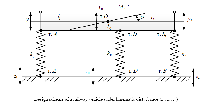
Introduction. The speed rise of railway transport and an increase in the loads on the axles of wheelsets necessitate the modernization of the existing fleet. Scientific studies in the field of rolling stock dynamics are aimed at taking into account the oscillatory processes that occur during the movement of railway vehicles in a traditional design. The attachment of supplementary elements was considered at the coupling level of two cars and the attachment of a third trolley in the center of gravity of the railway platform. The scientific literature has not paid enough attention to the construction of mathematical models that make it possible to assess the dynamic states of such constructive solutions. The objective of this study is to create a method for evaluating the dynamic conditions of a car. The situation is considered when an additional set of mass-inertial and elastic elements is introduced into its structure, and the general dynamic condition of the vehicle depends on the adjustment of their parameters.
Materials and Methods. The basic research tool is the structural mathematical modeling, which is based on an approach where the source design scheme is a mechanical oscillatory system in the form of a solid body on elastic supports with supplementary typical elements introduced into its structure. The dynamic analogue of the calculation scheme used is the block diagram of the automatic control system, the use of which provides detailing the connections between typical elastic and mass-inertia elements.
Results. A method for estimating the dynamic states of railway vehicles is proposed. It is based on the construction of mathematical models, taking into account the introduction of an additional structure of mass-inertia and elastic elements. The impact of additional parameters on the dynamic condition of the vehicle is investigated. Analytical relations have been obtained that provide reducing the dynamic loads on the major structural elastic elements when changing the corresponding parameters of a technical object. The transfer function of interpartial relations is given, which provides controlling the interaction between the coordinates of the vehicle movement under the action of two kinematic disturbances of the in-phase type.
Discussion and Conclusion. The generated mathematical model provides for assessment, monitoring and control of the dynamic state of the vehicle under conditions of kinematic disturbances. The research results can be used to modernize existing vehicles and create new ones with improved dynamics.
Introduction. Slender structures of subsea energy production systems are under constant influence of currents and waves. Hydrodynamic loads result from the interaction of subsea pipelines, umbilicals, equipment supports with fluid flows, and lead to the vortex formation in the area behind the structures. Vortex-induced forces are the sources of the cyclic loading. They accelerate gradually the fatigue damage, which may result in a failure. One of the ways to reduce the loads on subsea structures is to alter the shape of a cross-section, taking into account the flow regime. Dependence of the resulting hydrodynamic loads on the cross-sectional shape and relative position of structures has not been studied in details for the uniform flow in the critical mode. The current work is aimed at filling this gap. The research objective is to consider the impact of the distance between the structures, and also, the presence of a D-shaped structure, placed upstream relative to the group of three cylinders of different cross-sectional shapes.
Materials and Methods. The computational fluid dynamics approach was used in this work for numerical simulations of vortex-induced forces in the ANSYS Fluent software for cylinder with D = 0.3 m. Modelling was conducted with the Detached Eddy Simulation (DES) method, which combined advantages of the Reynolds-averaged Navier-Stokes equation (RANS) method and the Large Eddy Simulation (LES) method. The object of the research was the system of four structures in the 2D computational domain, which included the upstream D-shaped cylinder and the main group of three cylinders with the circular, squared and diamond shapes of the cross-section. The transient process was considered, where structures were under the influence of the uniform flow in the critical regime at Re = 2.5×10⁵.
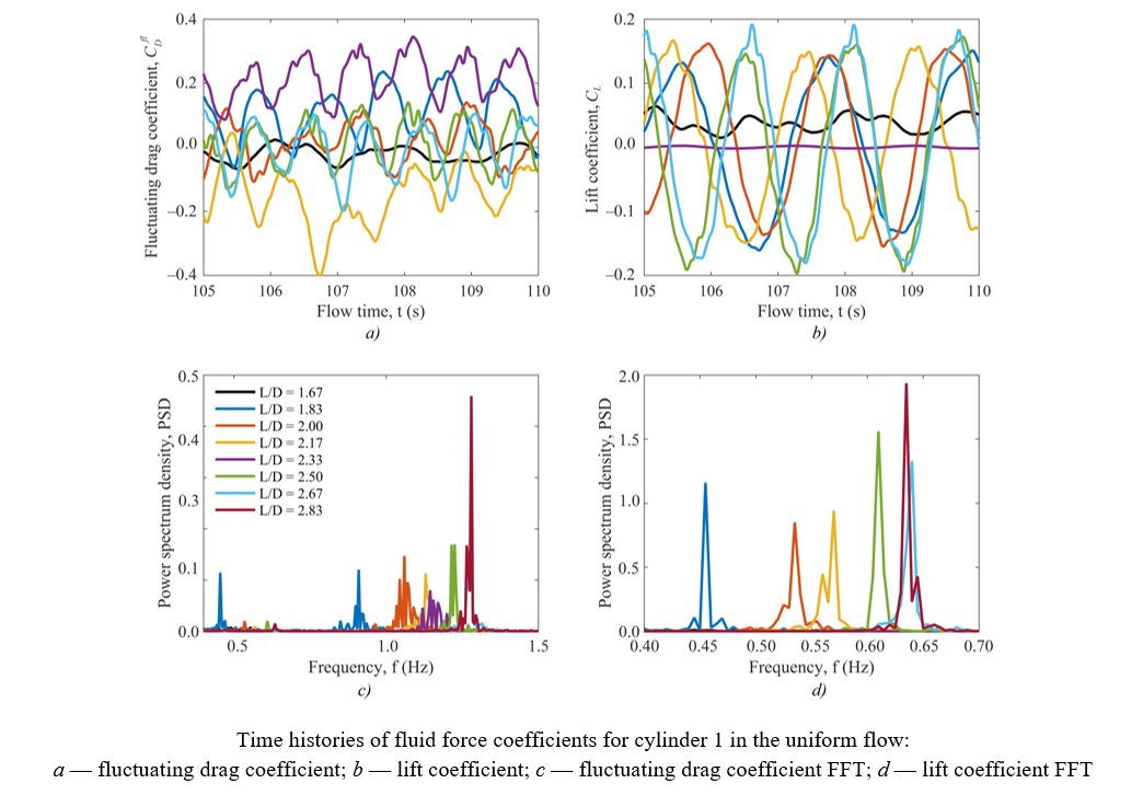
Results. Five sets of data were obtained in simulations for the time-dependent coefficients of the lift and drag forces: for the main system — of the D-shaped, circular, square and diamond structures, and also for the four systems — of only
D-shaped, only circular, only square and only diamond shaped structures. Additional analysis was conducted for the effect of the distance between the structures on the amplitude of fluctuating hydrodynamic force coefficients. The obtained results are presented as time histories of coefficients of the lift and drag forces, frequency analysis and contours of velocity, pressure and vorticity fields. The results indicate a positive effect of the upstream D-shaped structure on reducing the drag force, acting on the central structure in the group of three cylinders located downstream.
Discussion and Conclusion. The results of the performed studies facilitate the informed decisions regarding the arrangement of subsea structures in a group of four objects, depending on the cross-sectional shape and the distance between the structures. The upstream D-shaped structure provides reducing the hydrodynamic drag force acting on the central structure in the downstream group of three structures, thereby slowing the fatigue accumulation and increasing the time of safe operation.
Introduction. Devices for collecting and storing energy from the external environment are low-power sources of electric energy that are actively used. The autonomous devices for monitoring the damaged condition of various structures include them as well. The working element of these devices is a piezoelectric generator (PEG) — a converter of mechanical energy into electrical energy. The design of PEG is associated with the preliminary construction of their mathematical and computer models, with the help of which the calculation and optimization of structures is carried out. One of the ways to model and calculate PEG is to develop approximate calculation methods based on applied theories. The applied theories for calculating bending vibrations of multilayer piezoactive plates are known and previously developed in the literature. However, in the scientific literature there is not enough information about bending and shear vibrations as a tool for improving the efficiency of engineering calculations of the described structures. The objective of this work was to develop an applied method for calculating bending and shear vibrations of piezoceramic plates, including porous ones.
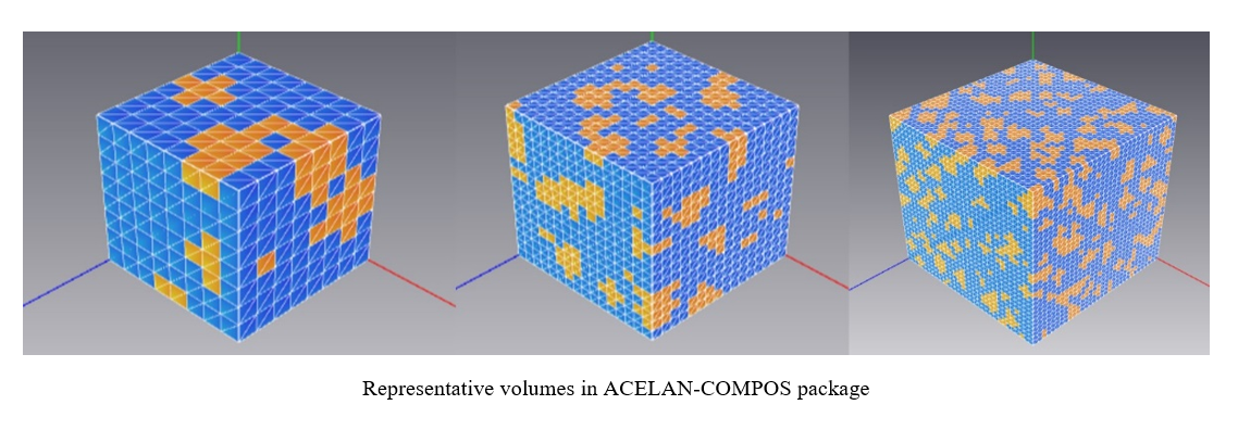
Materials and Methods. Piezoceramics PZT-4, including porous ones, were used as the piezoactive material of the plate. When using porous ceramics, the rigidity of the structure decreased to a greater extent than the piezoelectric modules, which made it possible to obtain a more effective PEG under mechanical action. The mathematical formulation was carried out within the framework of the linear theory of electroelasticity with plate polarization in thickness. The sides of the plate were electrodated, the right side was fixed, and a smooth contact in the vertical wall was set on the left side. Steady-state vibrations of the plate were caused by pressure on the front surfaces of the plate or the difference in electrical potentials at the electrodes. To calculate the characteristics of PEG, the authors proposed an applied theory based on hypotheses about the distribution of characteristics of the stress-strain state and the electric field.
Results. Transverse vibrations of a piezoceramic plate in the low-frequency region (below the first bending-shear resonance) were studied. Due to the fact that the mathematical formulation was considered within the framework of the linear theory of elasticity, the problem was divided into the sum of two. The first one took into account the mechanical effect: a distributed load and a transverse force at the left end acted on the front surfaces of the plate, and the potentials at the electrodes were zero. In the second task, there were no mechanical loads, but the potential difference was set at the electrodes. Based on hypotheses about the distribution of deformations, mechanical stresses and electric potential, both problems were reduced to a system of ordinary differential equations and boundary conditions. Comparison with the results of calculations by the finite element method in the ACELAN package showed the adequacy of the proposed applied theory in the low-frequency region.
Discussion and Conclusion. Since the formulation of the problem was considered in the linear theory of electroelasticity, and the low-frequency region was studied, the work succeeded in dividing the problem of bending-shear vibrations of a porous piezoceramic plate into two: bending — with mechanical action at zero potentials, and shear — when setting the potential difference and zero mechanical action. The corresponding hypotheses about bending and shear were used. Two systems of ordinary differential equations and boundary conditions, which were solved analytically without the use of “heavy” finite element packages, were constructed. To compare the results and confirm the adequacy of the proposed method, the finite element modeling of such tasks was carried out in a specialized ACELAN package. The comparison showed that the error in determining displacements and electric potential when using this approach, in the case of setting mechanical loads and potential differences, did not exceed 6%. The method developed in the paper can be applied in the design of piezoelectric generators for energy storage in the low-frequency region.
Introduction. Published studies on the rigidity of consoles under load focus on the issues of their deformation and destruction. Calculations of the inertia moment, fundamentally important characteristic of the strength of the rod, are described. However, the problem of significant time consumption for such calculations has not been solved. The presented study meets the lack. The objective of the work is to describe a new rapid method for analytical calculation of the shear stress distribution in the section of the console corresponding to the action of an external applied force. For the first time, tangential stresses are considered, and examples of calculating the inertia moment for two non-standard sections of the console are given in this context.
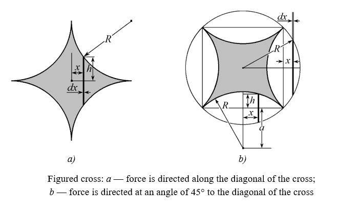
Materials and Methods. To develop a new method, the console was presented as a pack of plates oriented parallel to the vector of external force. The source calculations were based on the scheme of a console beam with a dedicated plate. The deformation of the rod elements was modeled taking into account the effect of a uniform shear stress field in the plate section. To validate the simplified calculation of the inertia moment of the sections, schemes of a square, ellipse, triangle, hexagon, six-pointed star, and a figured cross were used. Analytical and mathematical research methods were applied, specifically, the Huygens–Steiner theorem.
Results. A rapid valid method for calculating the inertia moment of the cross section of the console under loading has been developed. Its difference is the rejection of calculations for each section, taking into account the shape and other features. For any shape of the section, the beam is represented as a bundle of infinitely thin plates, their inertia moments are integrated, and a well-known solution for deflection of a thin plate is used. The method allows us to unambiguously show the distribution of tangential stresses at the end of the console, providing a given deflection, and tangential stresses are used for such solutions for the first time. Their profiles are obtained depending on the direction of the external applied force. Formulas for the inertia moments of complex sections — a six-pointed star and a figured cross — are derived for the first time. Each section is correlated with the stress distribution curve and its maximum value. This data is visualized in the form of diagrams. It is found that the inertia moment and the rigidity of the console do not change when the external applied force is rotated by 30° for a star-shaped section and by 45° for a square and a figured cross. In general, the tangent field depends on the geometry and on the orientation of the section relative to the external applied force.
Discussion and Conclusion. The proposed simplified approach to calculating the inertia moment of the cross sections of the consoles makes it possible to uniquely determine the field of tangential stresses at the end, which provides the appropriate value of the external applied force for the given deflection. Engineers and mechanics can use the results of the presented work in the calculations and modeling of deformation of rod structural elements.
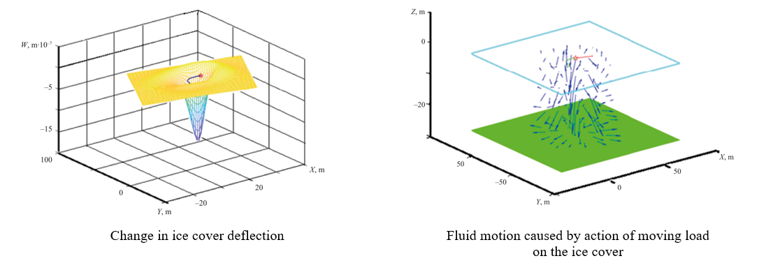
Introduction. The development of the polar areas of the World Ocean and the need to solve various problems associated with a large number of freezing inland water bodies issue new challenges for science. These challenges include the problem of studying the behavior of ice cover when exposed to various types of loads. Of great interest is the consideration of problems about the action of a moving load on the ice cover. A moving load simulates the effect of moving vehicles on ice. However, in papers devoted to the above problems, cases of load movement along a straight-line trajectory are considered. The objective of this research is to develop a method for studying the behavior of ice cover under the action of a load moving arbitrarily.
Materials and Methods. The article proposes a method for solving the problem of the action of a force moving along an arbitrary trajectory on the ice cover of a reservoir of finite depth. The problem amounts to solving a system of two differential equations. The first of them models the behavior of the ice cover, and it is the equation of vibrations of a viscoelastic plate. The second equation simulates the behavior of fluid in a state of potential flow, and it is Laplace's equation. To solve the system of differential equations, integral transformations in time, space and variables were used. The resulting solution was expressed through an iterated integral, which was calculated using numerical methods.
Results. The development and implementation of the method resulted in solving the problem of the movement of a concentrated force along an ice cover according to an arbitrary law. At the same time, studies were carried out on the behavior of displacements and stresses in the ice cover depending on the speed and acceleration of the movement of the vertical load, on the depth of the reservoir, and on the viscoelastic properties of ice. In addition, the distribution of the velocity vector of fluid particles along the depth of the reservoir was calculated.
Discussion and Conclusion. The proposed method is very effective for solving problems of moving loads acting on the ice cover of a reservoir of finite depth. It provides solving problems about the action of a load moving along an ice cover along a complex trajectory. The results obtained can be used to calculate the stress and displacement of the ice cover during the laying of ice roads or the construction of airfields on the ice.
MACHINE BUILDING AND MACHINE SCIENCE
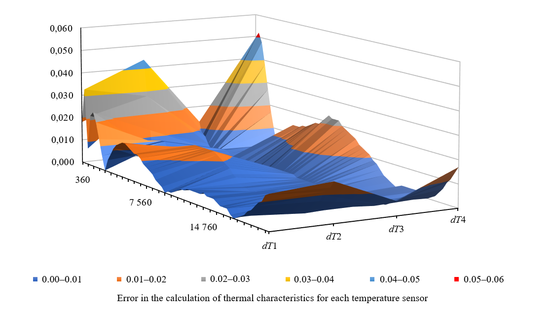
Introduction. Computer modeling allows engineers to make valid design decisions by accurately assessing the thermal characteristics of design objects. The implementation of digital twin technology in the process of designing technical facilities is the current direction of scientific research and development. To do this, it is necessary to develop computer models whose accuracy meets the requirements for digital twins. However, the scientific literature does not widely present the results of research aimed at implementing digital twin technology in the design process. The general issues related to the use of digital twins in various industries are mainly considered. Therefore, the objective of this study was the development of a digital model and a comparative analysis of the accuracy of calculations of thermal characteristics of the design object.
Materials and Methods. The main tool for conducting the research was the methodology proposed by the authors for developing a computer model of thermal characteristics for the implementation of digital twin technology. The numerical solution was implemented through constructing a thermal model for calculating the temperature field based on the finite element method in the ANSYS engineering analysis system from ANSYS, Inc. (USA). For the analytical solution, a computer model of thermal characteristics developed on the basis of the state-space method, implemented in the ANSYS Twin Builder module, was used. The state-space model was matched to the behavior of the original thermal model through approximating the transfer function to the stepwise response of the thermal load using the time domain vector approximation method. Verification of the constructed analytical model was carried out in the engineering calculation system MATLAB from the MathWorks company (USA). The research was carried out for a 400V machine model manufactured by NPO “Stankostroenie” LLC, Sterlitamak (Russia).
Results. The developed digital model makes it possible to calculate the thermal characteristics of the design object with high accuracy. The results of the comparative analysis showed a high degree of correspondence between the values of thermal characteristics obtained using the proposed digital model and the results of numerical simulation. The maximum error in calculating thermal characteristics did not exceed 0.1ºC.
Discussion and Conclusion. Computer modeling that combines numerical calculation methods and a scientific approach based on digital twin technology, provides obtaining the result as close as possible to the results of experiments. The digital model proposed in the study is an effective solution, since it provides performing calculations to evaluate thermal characteristics in real time, which is one of the most important requirements for the implementation of digital twin technology.
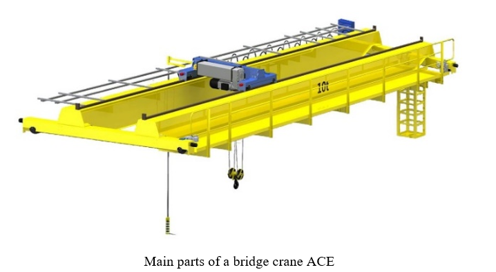
Introduction. The dynamic loads during the start-up of a bridge crane can cause excessive stress in the structure and components, leading to potential safety hazards and increased wear and tear. To reduce the influence of the dynamic loads, various strategies can be implemented including optimization of the acceleration and deceleration profiles, using the soft start controls, implementing the vibration damping systems. It is vital to ensure that the proper crane maintenance and inspection protocols are in place. By reducing the impact of dynamic loads during the start-up, the overall performance and longevity of a bridge crane can be improved, ultimately enhancing safety and efficiency of the industrial operations. The present research offers a new approach to improving the efficiency and safety of industrial operations by providing a more precise account of the dynamic loads during the start-up of a bridge crane. The objective of this study is to develop a mathematical model for investigating the mechanical properties of the bridge cranes by analyzing the dynamic loads that occur during lifting operations.
Materials and Methods. The development of the mathematical model was based on the kinetic model of the system, which included three connecting blocks and two flexible connections for a more accurate description of the bridge crane structure. Lagrange’s equations incorporating the information about the geometry and structure of a bridge crane were used. They made it possible to describe the motion of a system with the multiple elements and degrees of freedom. Processing and analysis of the results of the mathematical model were carried out in the MATLAB program using the Runge-Kutta method.
Results. As a result of the research, a mathematical model was developed to study the dynamic loads affecting a bridge crane during lifting operations. Graphs describing the dependences of speed, acceleration, load, and rope angle over time, and their influence on the crane beam were plotted. The changes in these parameters over time, including their maximum values, were analyzed. The reasons for load changes and factors influencing the extension of lifting machines’ service life as well as reducing metal consumption during production thereof were identified.
Discussion and Conclusion. The developed mathematical model and its numerical solution using the specialized software (MATLAB) allow for conducting the dynamic analysis of the bridge crane structures and determining the optimal design solutions. The analysis of the factors influencing the load changes leads to the conclusion that the use of this model can significantly reduce the load magnitudes and metal consumption, as well as increase the service life of lifting machines. The results obtained with the developed mathematical model and its numerical solution are useful for optimizing the crane structures, providing compliance with the operational requirements, and extending the service life of lifting machines.
INFORMATION TECHNOLOGY, COMPUTER SCIENCE AND MANAGEMENT
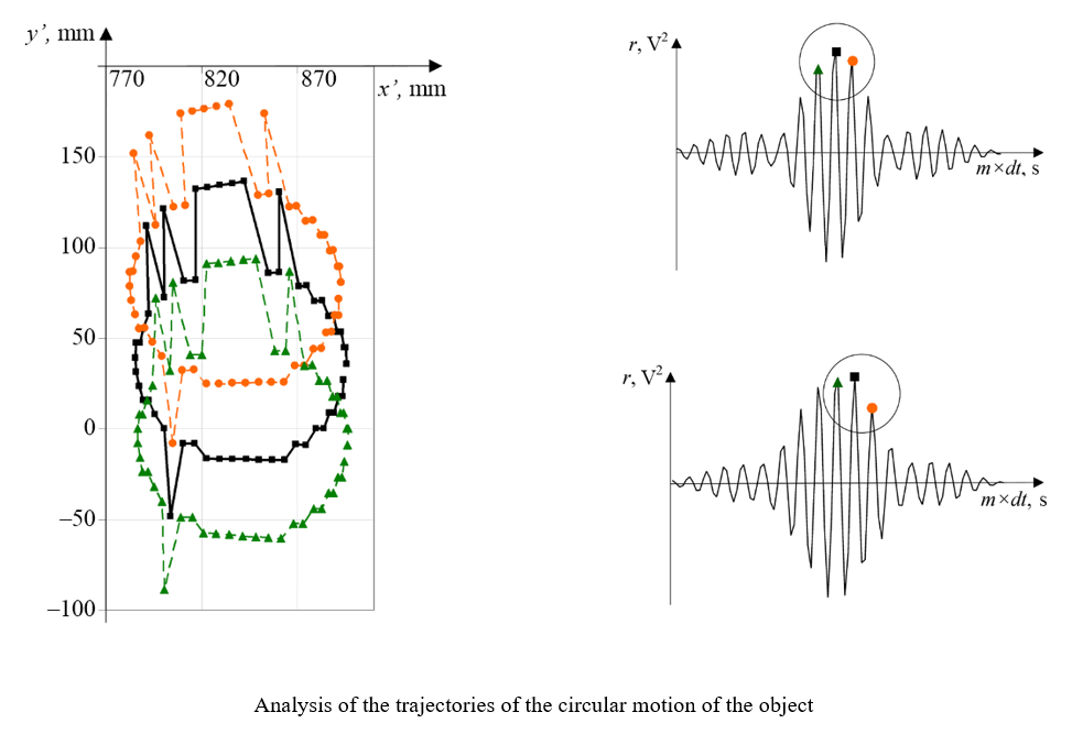
Introduction. Safety of navigation and development of underwater mineral deposits require the accurate detection of various underwater objects. The literature discusses the issues of tracking their motion and trajectory. Sonar methods are proposed to maintain high accuracy of underwater object positioning. High accuracy of the bearing of stereo sensors with an ultrashort base is noted. However, this equipment is sensitive to the sampling rate of the signals, which causes “sampling noise”. There are no publicly available publications dedicated to the solution to this problem. The presented study is designed to fill this gap. This work is aimed to study the possibility of obtaining data clarifying information about the bearing of underwater objects through using the phase information about echoed probing signals and an additional procedure for resampling the source data.
Materials and Methods. The location of the object was determined using the experimental complex for studying hydroacoustic sensors created by V.A. Shirokov and V.N. Milich at the Udmurt Federal Research Center, the Ural Branch of the Russian Academy of Sciences. A stereo sensor with a small base (30 mm) was used compared to the distance to the object (≈800–900 mm). Digital filtering methods and mathematical apparatus of correlation analysis of return hydroacoustic signals obtained by the phase method were used for data processing.
Results. The results of comparing two methods for determining the bearing on an object are presented: by the difference in the time of arrival of the pulse-leading edges and by the maximum of the cross-correlation function (CCF). The change in bearing as the object moves, is graphically shown. The use of the leading edge of the signal caused small outliers of values along the entire bearing curve (less than 0.12 rad). At the maximum CCF, emissions were recorded only in some areas, but they were quite significant (about 0.17 rad). It showed how to select points corresponding to a smoother and more valid object trajectory, and how to work with erroneous points. The presented method of error correction can be implemented programmatically. With a quasi-harmonious signal, rare measurements of the original signal are interpolated by frequent calculated values. Thanks to this virtual increase in the sampling rate (oversampling), intermediate indicators can be recorded in the digitized source data. Interpolation of the signal values by a cubic spline allowed us to obtain 20 points for 1 period of the signal instead of 5 points in the original version. In this case, the trajectory formed with the maximum CCF is more correct.
Discussion and Conclusion. The direction-finding problem can be solved with the accuracy required for practical application. Taking into account the factor of smoothness and continuity of the object's trajectory makes it possible to qualitatively correct the selection of the maximum of the cross-correlation function of the stereo sensor signals. The proposed methods have great potential for the development of underwater vision systems.